| Subject: | Slow or No Engagement of Automatic Transmission, No Start, Blank PRNDL Display,
Flashing PRNDL, DTC P0708, P0872, P0847, P0875, P1711, P1713 or U1000 Set (Diagnose
Condition, Repair According to Procedure) |
| Models: | 2001-2004 Chevrolet Silverado |
| with Allison® LCT1000 Automatic Transmission (RPO M74) and |
| 6.6L Duramax™ Diesel Engine (RPO LB7) or 8.1L Gas Engine (RPO L18) |
This bulletin is being revised to add model years and additional model information
and add graphics. Please discard Corporate Bulletin Number 02-07-30-011B (Section 07
-- Transmission/Transaxle).
Condition
Some customers may comment on one or more of the following conditions.
| • | The PRNDL display is flashing. |
| • | The engine will not start. |
| • | The "Service Engine Soon" Indicator lamp is illuminated. |
| • | The transmission does not shift properly. |
| • | The vehicle will not move, transmission will not engage. |
Cause
Moisture contamination within the Park Neutral Position (PNP) Switch may cause
this condition. This is sometimes referred to as the Neutral Start Back-up (NSBU)
Switch. On a left turn, water spray from the left front tire is directed directly
at this switch. Proper installation of the "Front Shield" and "Rear
Shield" are essential for proper repairs.
Technician Diagnosis

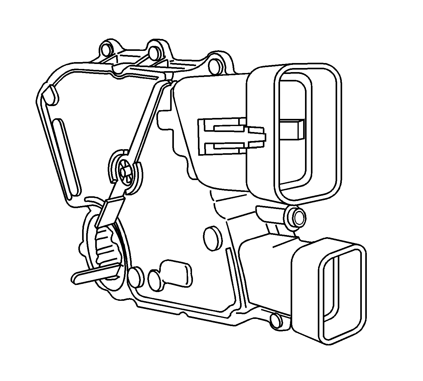
This bulletin ONLY applies to vehicles equipped with a two
connector PNP switch as shown above.
A complete and through diagnosis must be performed by a qualified electrical
technician to determine the cause and avoid needless replacement of good components.
Important: The Transmission Control Module (TCM) and
or the Pressure Switch Manifold (PSM) should NOT be replaced unless properly diagnosed.
They are probably not the cause of the concern. It is often assumed the module is
the cause of the concern when, in fact, it is another component or the wiring between
the components that causes the concern.
Important: Remember, everything starts with a properly
operating Neutral Start Back Up (NSBU) switch. The NSBU switch has been incorporated
into what is now called the Park Neutral Position (PNP) switch. If the PNP switch
does not provide the proper voltage signal to the module indicating the transmission
is in either Park or Neutral, the module will not allow the starter operation. After
the engine is started, and the shift lever is moved to either Reverse or one of the
drive positions, the range selected portion of the PNP switch portion provides a voltage
input to the module as to what range the driver has manually selected for transmission
operation. The module then controls pressures, shift points and other transmission
functions based on the voltage input received from the range portion of the PNP switch.
The technician may find one or more of the following conditions. The list of
these conditions does not imply any type of frequency or order. They are random events
and may occur in any order.
| • | DTC P0708, Neutral start/backup (PNP or NSBU) switch |
| • | DTC P0847, Pressure Switch Manifold (PSM) |
| • | DTC P0872, Pressure Switch Manifold (PSM) |
| • | DTC P0875, Pressure Switch Manifold (PSM) |
| • | DTC P1711, Pressure Switch Manifold (PSM) |
| • | DTC P1713, Pressure Switch Manifold (PSM) |
| • | DTC U1000, Serial Data Communications |
| • | Slow or No Engagement of Automatic Transmission |
Blank PRNDL Display
A blank PRNDL display may indicate a condition with the PNP switch and/or one
or more of the four signal circuits from the PNP to the TCM.
- Pin A, Circuit 771 (BLK/WHT)
- Pin B, Circuit 773 (GRA)
- Pin C, Circuit 776 (WHT)
- Pin D, Circuit 772 (YEL)
Or, a blank PRNDL display may also occur if an out of line condition exists
with the Serial Data Circuit (CKT 2470, yellow wire) from the TCM to Splice
Pack 205.
Diagnostic Tip
- Connect the Tech 2® to the vehicle.
- Power up the Tech 2®.
- Does the Tech 2® communicate with the TCM? If not, inspect
the serial data circuit, CKT 2470 (Yellow wire), between the TCM and Splice
Pack 205. Specifically inspect connector C106, a five terminal connector located
below the left side underhood bussed electrical center, directly beneath the red
battery cable terminal connection. Perform a mating terminal pull test on all of
the terminals in this connector. Repair as required.
- Observe the Gear Selected screen on the scan tool. The following values
should be shown on the Tech 2® display and the vehicle's instrument panel
cluster (if equipped with the I/P display).
| • | "8" (shifter should be in the Park position) |
| • | "7" (shifter should be in the Reverse position) |
| • | "5" (shifter should be in the Drive position) |
| • | "3" (shifter should be in the Third gear position) |
| • | "2" (shifter should be in the Second gear position) |
| • | "1" (shifter should be in the First gear position) |
| • | "0" (shifter should be in the Neutral Position) |
If the Gear Selected display does not match the shifter position in the vehicle,
diagnose using one of the following methods.
| • | Obtain a new PNP switch kit, P/N 29540479, from the Parts Department. |
| 1. | Disconnect the wiring connector from the original transmission mounted
PNP switch. |
| 2. | Connect the new switch to the wiring connector. |
| 3. | Return to Step #4 above and observe the display as you rotate the switch.
If all positions indicate properly, refer to the Correction section below. |
| • | Use the DTC P0708 diagnostic chart in Service Information (SI)
under Transmission/Transaxle/Automatic Transmission - Allison. Reference SI Document
ID #769549 for the wiring schematic for this symptom. |
The PNP switch, as referenced in SI, is known as the NSBU switch in the Parts
information. It is now serviced with a Park Neutral Position Switch Kit, P/N 29540479.
Flashing PRNDL Display
A flashing PRNDL display may be the result of incorrect sensor inputs or transmission
abuse protection modes being received by the TCM. The following are some of these
conditions:
| • | The transfer case is/was in Neutral. |
| • | The transfer case is/was shifted into Neutral when the vehicle is moving. |
| • | A decrease of the input turbine speed was not detected when the gear
selector was moved into any gear. |
| • | A low transmission fluid level. |
| • | A misadjusted PNP/NSBU switch. |
| • | Turbine input speed or output speed sensor failure. |
| • | Failures of the shift solenoids to route the transmission oil to the
proper clutch assemblies within the transmission. |
| • | Failures of the transmission clutch packs (C1 or C5 for first gear, C3
or C5 for Reverse). |
| • | Failure to detect proper line pressures when a gear range is selected,
which may be the result of normal maintenance such as a transmission fluid change
having been completed, or the transmission pan was removed for a filter replacement
or other type service. |
Transmission abuse protection modes are encountered when a customer performs
one of the following types of maneuvers:
| • | Shifting from Neutral to Drive/Reverse when the engine RPM is greater
than 1400 RPM. |
| • | Shifting from Drive to Reverse when the throttle position (TPS) is greater
than 25%, such as rocking the vehicle when stuck in an attempt to free the vehicle. |
| • | When the transmission output speed is greater than 300 RPM from
attempted changes in direction such as Reverse to Drive, Drive to Reverse or Neutral
to Reverse shifts. |
When the TCM encounters any one of the above conditions, the TCM will flash
the PRNDL and default the transmission to Neutral. A flashing PRNDL indicates something
is/was incorrect. The transmission may need the attention of a qualified service
technician.
Correction
- Disconnect the wiring harness from the PNP switch.
- Disconnect the shift linkage/cable from the shift lever at the transmission.
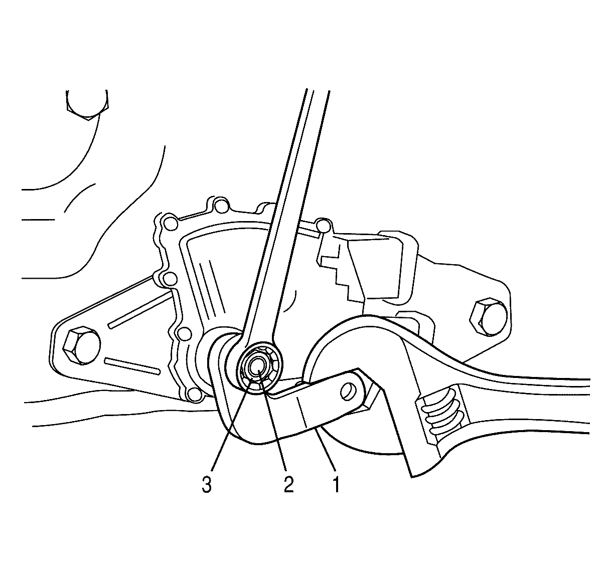
- With a wrench keeping the shift lever from rotating, remove the nut from
the end of the selector shaft.
- Use a file to remove any burrs or raised metal where the selector lever
was seated against the shoulder of the selector shaft.
Important: If the old PNP switch will not slide from
the selector shaft without the effort, the selector shaft may need to be filed to
remove flaring on the end of the selector shaft. This is important, installing the
new switch onto a selector shaft that has damage will cause damage to the new PNP
switch.
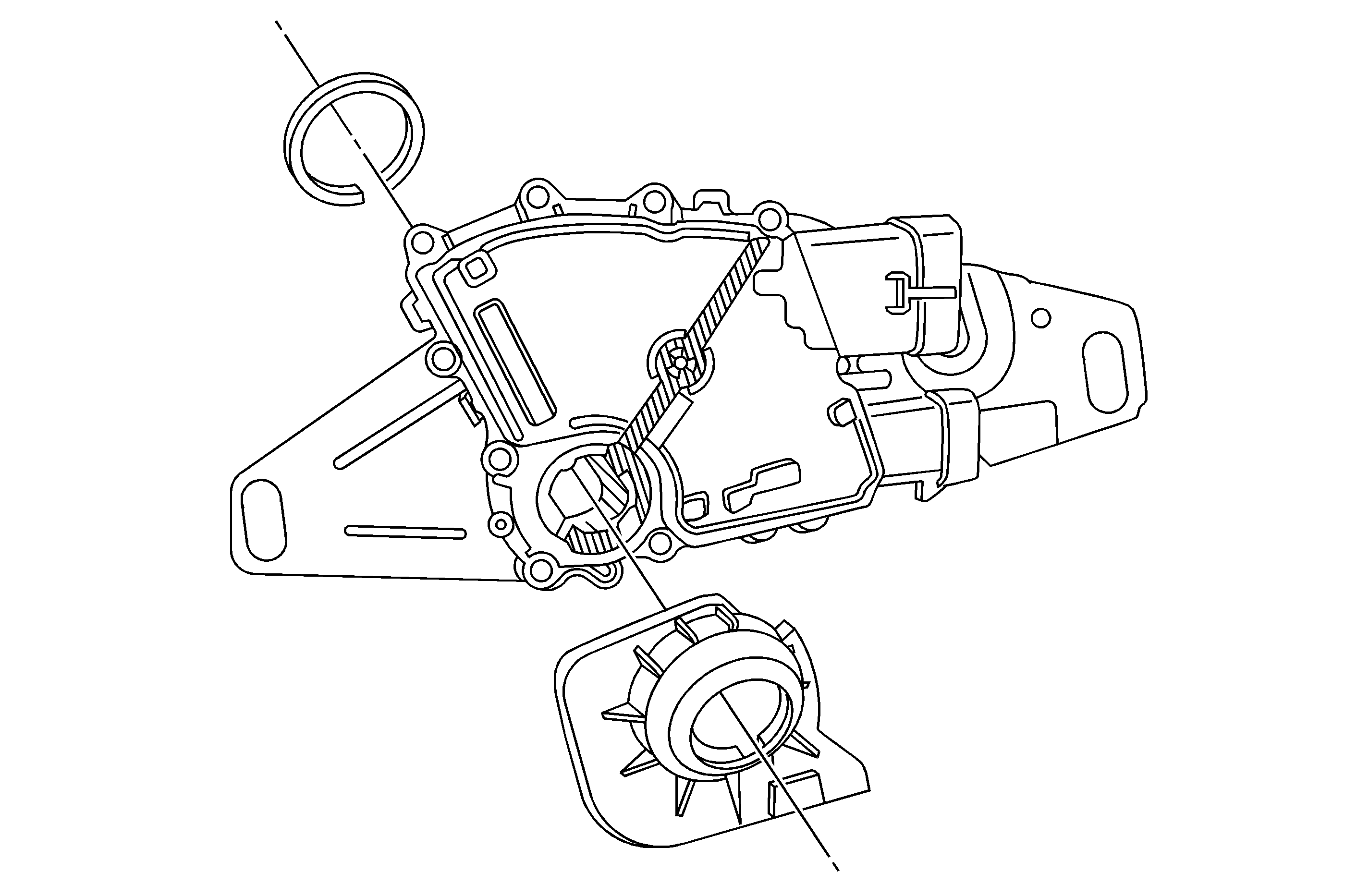
- Remove the two bolts that attach the PNP switch and remove the switch by sliding
it outward over the selector shaft.
- Make sure the selector shaft is in the N (neutral) position (using a wrench
on the selector shaft flats, rotate the shaft to its furthest clockwise position and
then rotate counterclockwise two detents).

Important: If the new PNP switch will not slide onto
the selector shaft easily, the selector shaft may need to be filed to remove flaring
on the end of the selector shaft. This is important, installing the new switch onto
a selector shaft that has damage will cause damage to the new PNP switch.
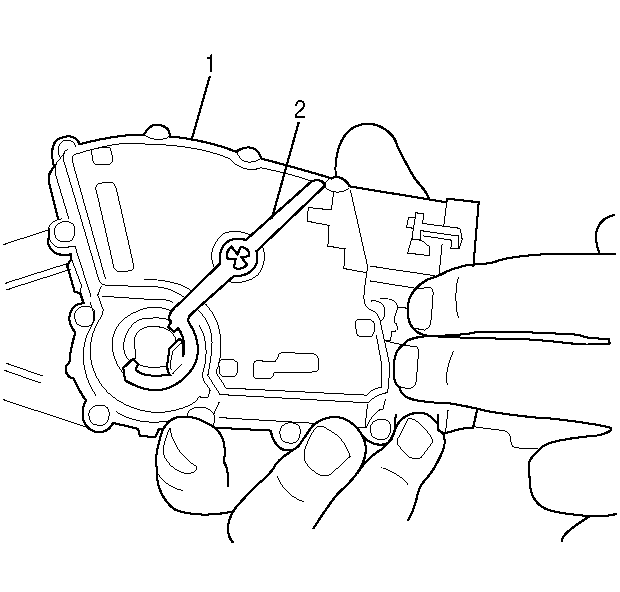
- Slide the new PNP switch over the selector shaft with the neutral assurance
bracket 920 facing outward and maintaining the correct PNP switch orientation to the
selector shaft. Install and hand tighten the two PNP switch attaching bolts so that
the PNP switch and bracket may be rotated within the adjusting slots with some effort.
- While holding the neutral assurance bracket in engagement with the PNP
switch, tighten the two bolts that attach the PNP switch to the transmission case.
Tighten
Tighten the bolts to 27 N·m (20 lb ft).
- Remove and discard the neutral assurance bracket.

Important: Installation of the front shield and rear
shields are important. Without proper installation of the shield, a return repair
is probable. Follow all directions as listed on the installation instructions sheet
included in the Switch kit, P/N 29540479.
- Fit the new shield onto the PNP switch so that it fits securely against the
switch. Make sure this is done before reinstalling the shift lever.

- Reinstall the shift lever. With a wrench keeping the
shift lever from rotating, install the nut on the end of the selector shaft.
Tighten.
Tighten the nut to 24 N·m (18 lb ft).
- Connect the wiring harness connectors to the PNP switch.
- Attach the selector cable to the lever. Check and adjust if needed.
- Go back to step 4 of the Diagnostics and insure the Tech 2 readings
match the shift lever positions.
Important: Clear all DTCs before returning the vehicle
to the customer.
- Return the vehicle to the customer.
Parts Information
Part Number
| Description
|
29540479
| Switch kit, Park Neutral Position
|
Parts are currently available from GMSPO.
Warranty Information
For vehicles repaired under warranty, use:
Labor Operation
| Description
| Labor Time
|
K5228
| Switch, Park/Neutral Position - Replace
| 0.5 hr
|
Add
| Diagnosis Time
| 0.0-0.3 hr
|


