Allison Transmission Leaks, Slips, Vehicle Will Not Move (Replace Rear Extension Housing, Change Torque Converter Relief Spring/Lube Regulator Spring, Diagnose/Repair Driveline Imbalance)

| Subject: | Allison® Transmission Leaks, Slips, Vehicle Will Not Move (Replace Rear Extension Housing, Change Torque Converter Relief Spring/Lube Regulator Spring, Diagnose/Repair Driveline Imbalance) |
| Models: | 2001-2003 Chevrolet Silverado 2500/3500 Series Pickup Models (4WD Only) |
| 2001-2003 GMC Sierra 2500/3500 Series Pickup Models (4WD Only) |
| with Allison® 1000 Series Automatic Transmission (RPO M74) |
This bulletin is being revised to update vehicle build dates. Please discard Corporate Bulletin Number 03-07-30-031D (Section 07 - Transmission/Transaxle).
Condition
Some customers may comment that the transmission leaks from the rear, slips, or the vehicle may not move.
Cause
This condition may be the result of a cracked extension housing caused by a driveline imbalance. Driveline imbalance may be caused by any of the following components. This is not an exhaustive list and other conditions that are not noted here may be found on vehicles.
| • | Damaged or worn U-Joints (inspect both front and rear driveshafts). |
| • | A front or rear driveshaft that is out of balance due to the following conditions: |
| - | Foreign material stuck on the front or rear driveshaft (mud, concrete, tar, etc.). Nothing should be on the driveshaft. It must be clean. |
| - | A damaged front or rear driveshaft (bent, dented, etc.). |
| - | Foreign material that affects the motion of the U-Joints. All of the U-joints must be free to move within their full range of motion. |
| - | Balance weights missing from a front or rear driveshaft. |
| • | For additional Items that affect driveline imbalance, refer to Corporate Bulletin Number 02-07-30-024B, Diagnosis of Cracked or Broken Transmission Case, and the Vibration Diagnosis and Correction sub-section of SI. |
Correction
Use the service procedure below to replace the rear extension housing (steps 1-42 & 86-101) and to access and change the torque converter relief spring and lube regulator spring in the front support assembly (steps 43-85). The converter relief and lube regulator springs are being changed to reduce the possibility of setting multiple DTCs or experiencing a delayed engagement on the first start-up after sitting unused for an extended period of time. The converter relief and lube regulator springs are used in 2003 production and do not require changing on 2003 models built AFTER Indianapolis Plant Serial Number 6310234829, Baltimore Plant Serial Number 6320154492 and Remanufactured Transmission Serial Number 9620011913 .
Notice: Do not attempt to replace the transmission extension housing with the transmission in the vehicle. Several internal components are held in place by the housing and they will come out of alignment during reassembly. Attempting
to do so will result in the following conditions:
• Displacement of eighteen (18) clutch springs • Damage to C5 clutch plates • Damage to P2 & P3 thrust bearings • Improper transmission end play • Shop comebacks
Notice: Failure to diagnose and repair the cause of the driveline imbalance may result in a repeat cracked extension housing.
Important: When performing this repair, the following steps must be taken to reduce the possibility of setting a DTC P0872 after the repair.
• Clean the transmission oil pan thoroughly. • Replace the fluid filter located in the oil pan with P/N 29537965. • Replace the spin-on fluid filter with P/N 29539579. • Flush the transmission oil cooler and lines using J 45096. • When the transmission is refilled, make sure that the oil level is in the "cold" range with the engine running and the transmission in Park. Do not shift from Park into a forward or reverse range until the oil is in this "cold"
range.
Important: After completing this modification, the transmission control module (TCM) shift adapts must be relearned for proper transmission operation. For MY 2001 using the Tech 2®, select Special Functions (F2), Transmission Output Controls (F1), Preset All Tap Cells, Disconnect the Tech 2®. This action will reset all clutch adaptives and requires the vehicle to be driven. For MYs 2002-2003, follow the procedure outlined in Corporate Bulletin Number 02-07-30-032A to quickly relearn the transmission shift adapts.
Tools Required
The following special tools will be required for the completion of the repair.
| • | J 46695 Digital Depth Micrometer |
| • | 2 Guide Pins (M10 X 1.5 mm, 75 mm long bolts with the heads removed, locally obtained) |
| • | J 5959 Dial Indicator Set |
| • | J 21366 Converter Holding Strap |
| • | J 44723 Transmission Adapter Plate |
| • | J 24446 Rear Bearing Installer |
| • | J 43769 Spanner Nut Wrench 4WD |
| • | J 3685 TransJel™ |
| • | J 46409 - Torque Converter Lifting Handles |
| • | 6 M10 X 1.5 Bolts (38 mm (1 ½ in) |
| • | J 43773 Spring Compressor |
| • | J 43772 Seal Installer |
| • | J 45096 Transflow® Transmission Cooling System Service Tool |
For transmission removal, refer to the proper Service Information Document listed below. After removal, return to this document for the transmission modification procedure.
| • | For vehicles equipped with the Duramax™ Diesel (LB7), refer to Document ID #758397. |
| • | For vehicles equipped with the 8.1L gas engine (L18), refer to Document ID #758399. |
Caution: The Allison® 1000 Series (M74) transmission has a dry weight of approximately 150 kg (330 lbs). The torque converter has a dry weight of approximately 29 kg (63 lbs).
• Use caution when removing, installing, servicing or moving the transmission in order to prevent personal injury. • Get assistance when lifting the transmission. A hoist is the preferred lifting device. Ensure that the lifting device is adequate to support the transmission.
With the transmission supported on the transmission stand, perform the following steps.
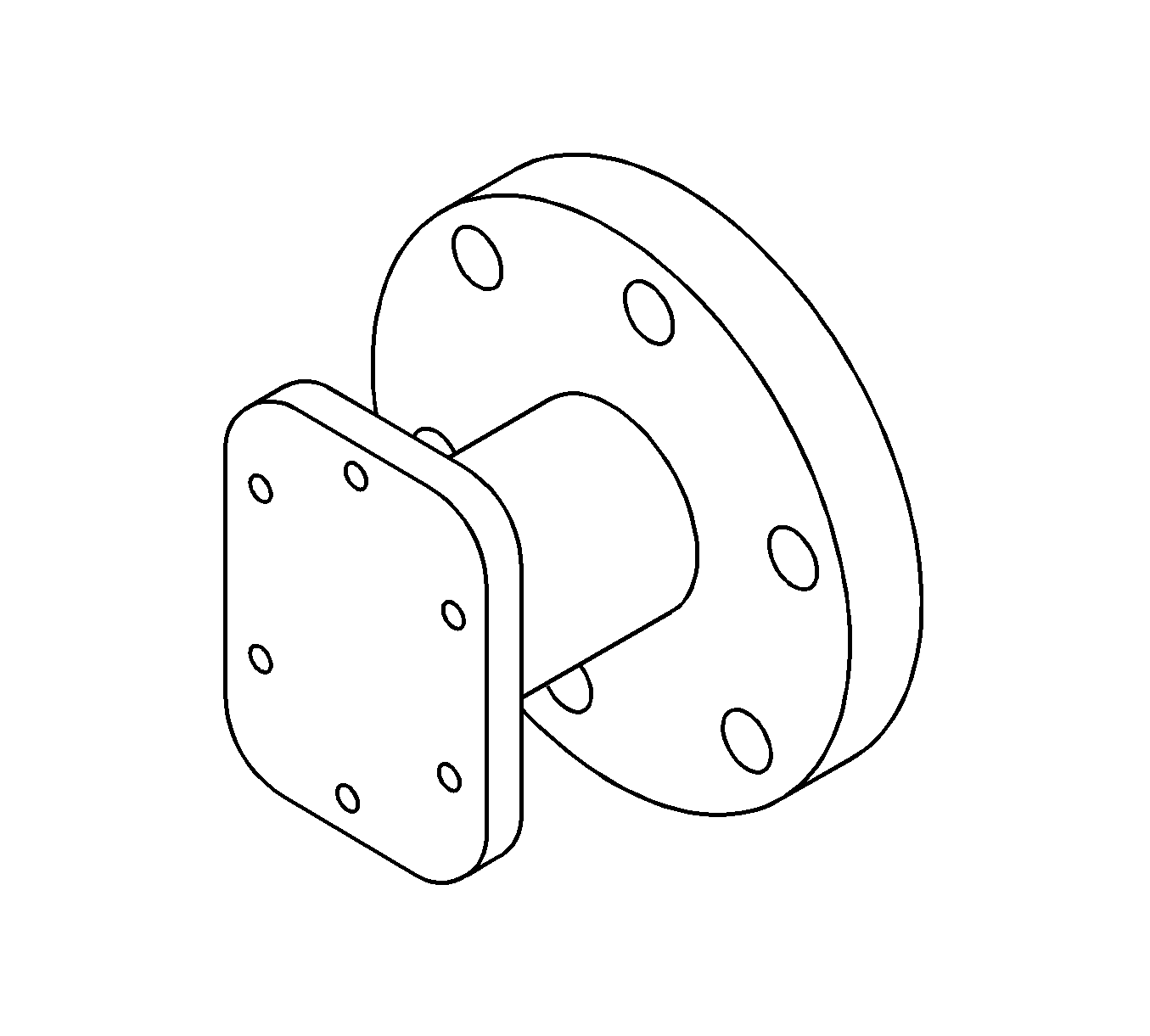
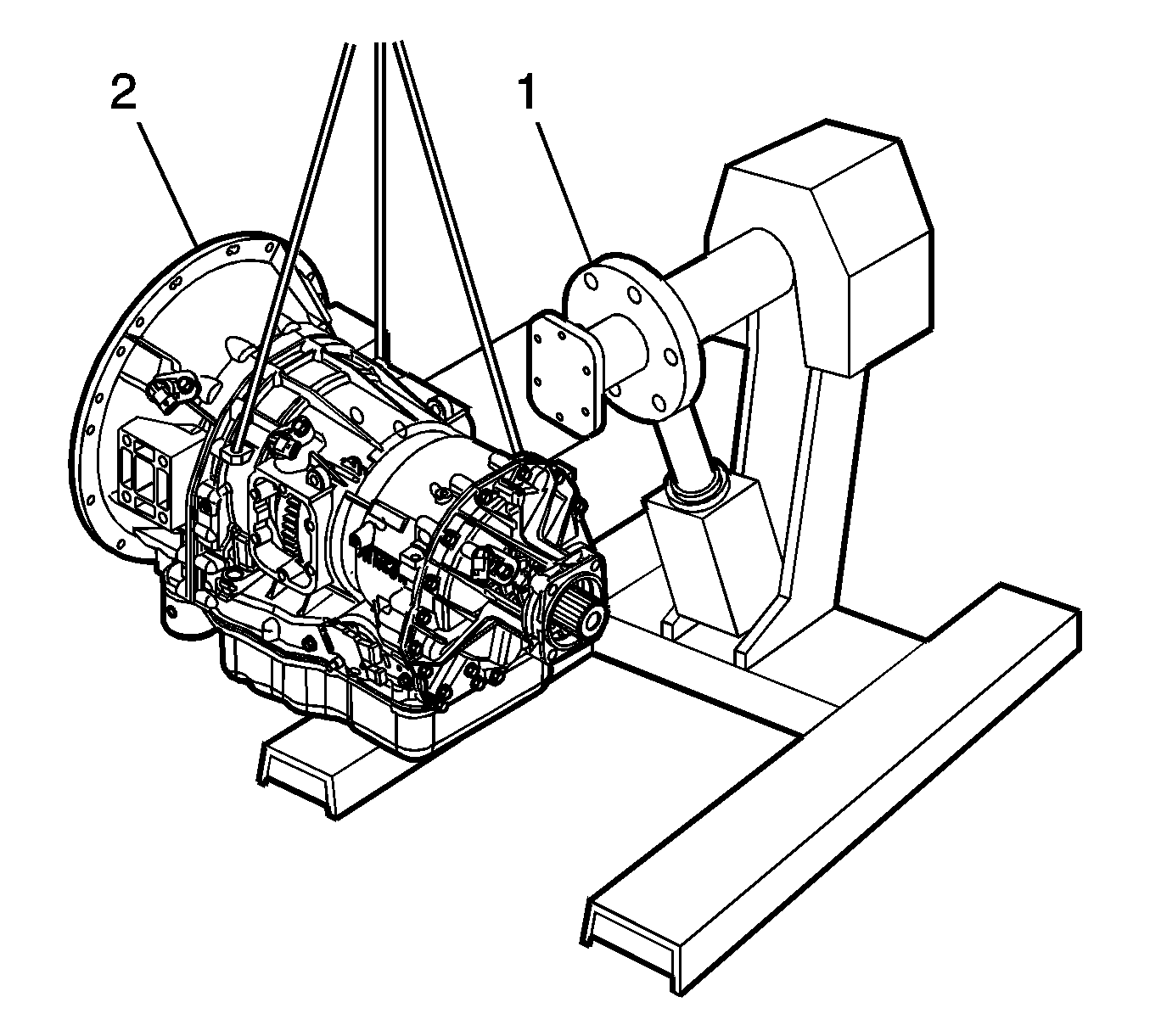
- Locate the Transmission to Engine Stand Adapter Plate J 44723.
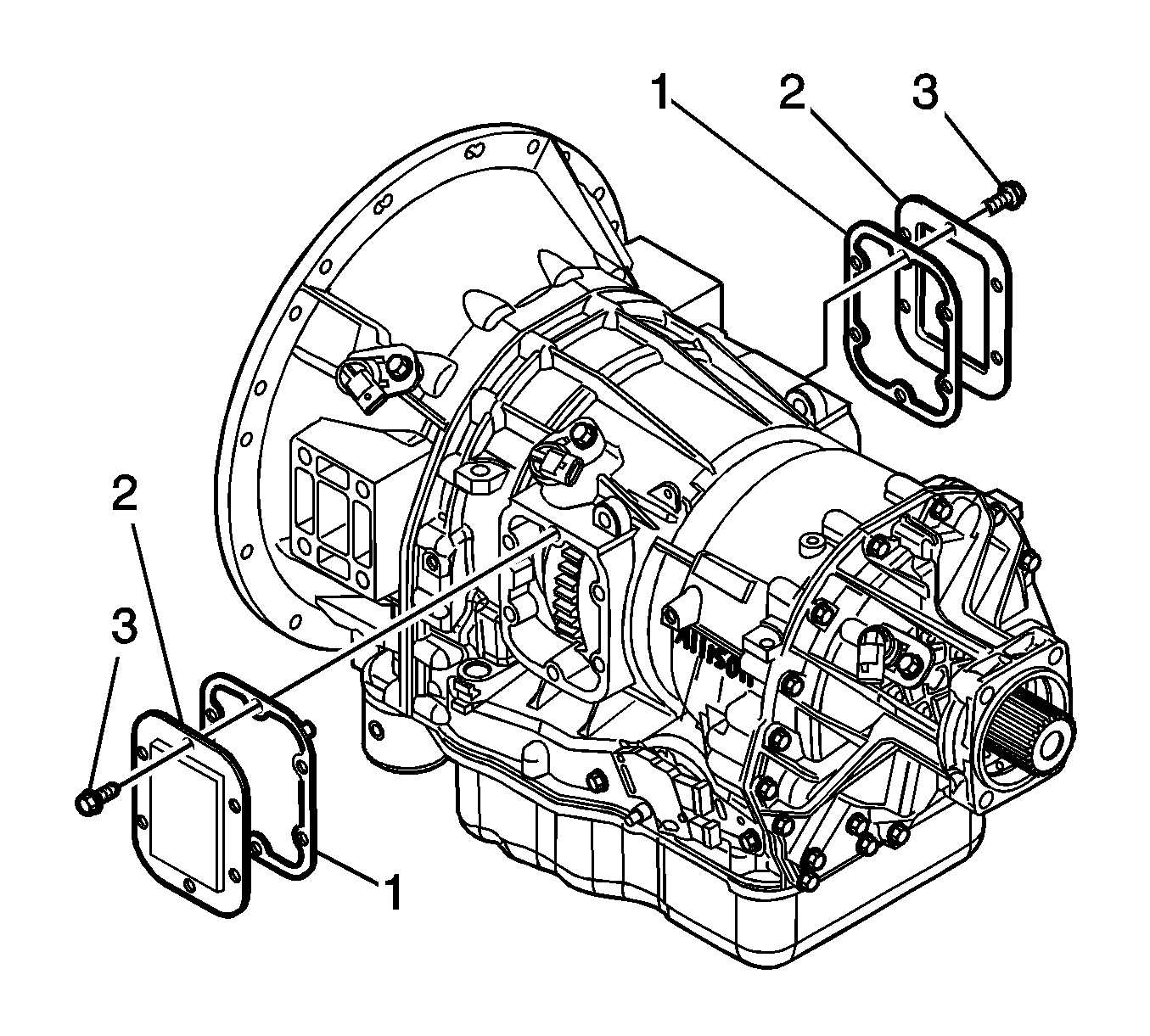
- Remove BOTH of the transmission PTO side covers (2).
- Locate six M10 x 1.5 bolts (38 mm (1½ ) long).
- With the transmission supported on the transmission jack, attach the J 44723 Adapter Plate to the PTO side cover opening with the six bolts.
- With the aid of the hoist, transfer the transmission to the engine stand.
- Position the transmission so that the converter housing is pointed upward and secure so the transmission will not rotate in the engine stand.
- Remove the Converter Holding Strap J 21366.
- Install the J 46409 - Torque Converter Lifting Handles to the converter and lift the converter from the transmission. Place the converter in a position so it may drain into a suitable receptacle.
- Rotate the transmission so that the pan is facing upward.
- Remove the transmission oil pan.
- Thoroughly clean the inside of the transmission pan.
- Remove and DO NOT REUSE the transmission suction filter.
- Rotate the transmission so the extension housing is pointing upward.
- Rotate the transmission selector shaft to its full clockwise position. This ensures that the transmission is in the "PARK" position.
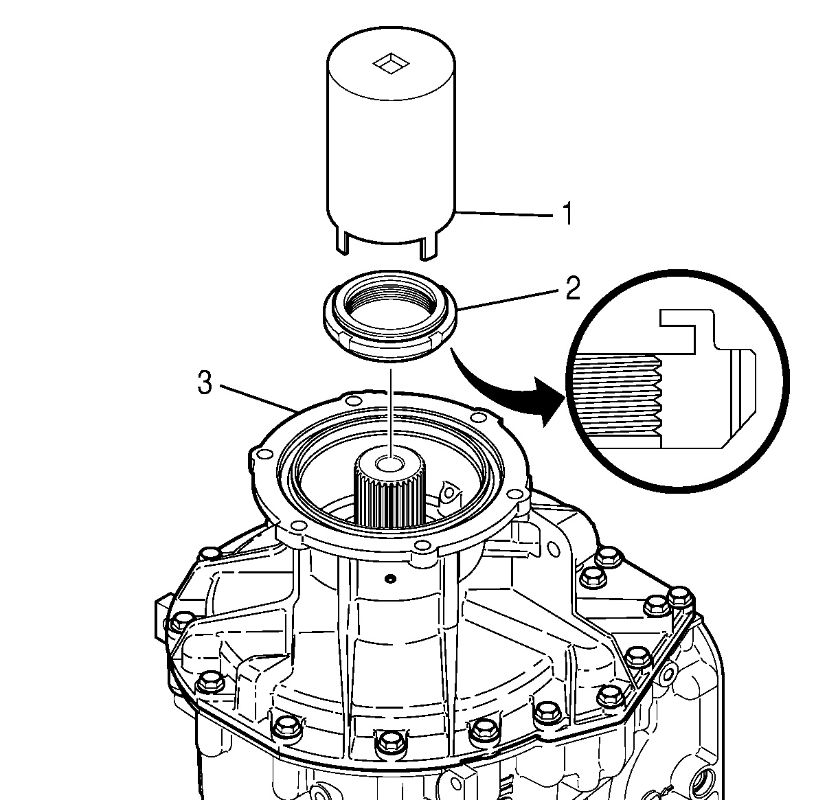
- Use tool J 43769 Spanner Nut Wrench-4WD (1) and remove the output nut (2).
- Remove the output ball bearing assembly beveled retaining ring.
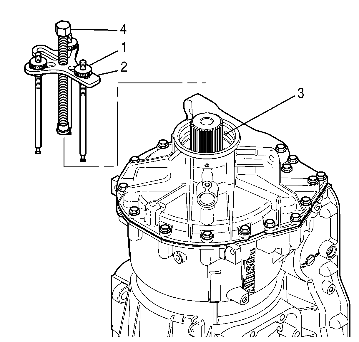
- Assemble the Universal Puller J 24420-B, with three legs J 43910.
- Place the puller into position and remove the ball bearing from the case and the output shaft. Save the bearing.
- Locate the selective spacer and discard.
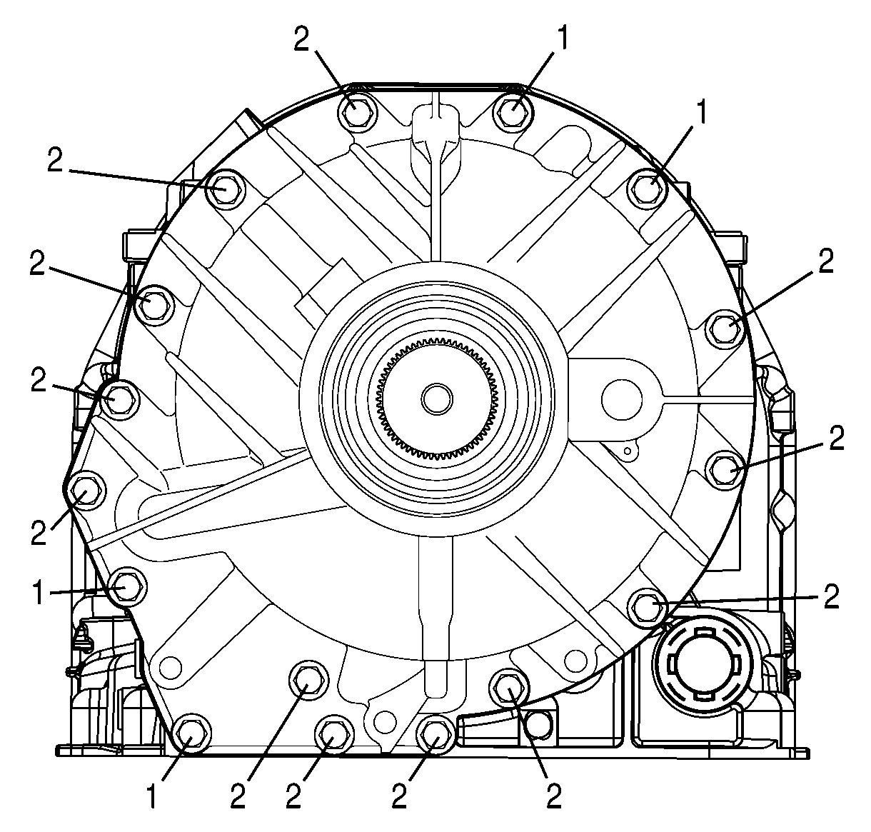
- Remove the four bolts numbered (1).
- Remove the twelve bolts numbered (2).
- Separate the rear extension housing (1) from the transmission case (3). The extension housing has places for insertion of a small pry bar at two locations. Pry only at these designated areas. The housing will need to clear the case dowel pin (4) and the parking pawl support pin (5).
- Remove the rear extension housing from the transmission.
- Remove the rear cover gasket (2) and discard.
- Replace the park pawl spring (2).
- Install a new gasket to the case.
- Inspect for proper positioning of the (18) clutch springs.
- Inspect and clean, if required, the new extension housing assembly.
- Install the new extension housing into position.
- Install the four bolts in position (1). Slowly draw down the extension housing until it is seated against the case by alternately hand tightening the bolts.
- Install the twelve bolts in position (2).
- With the aid of depth indicators, you must make a calculation to determine which selective shim to install before installing the new ball bearing assembly.
- Place the selected selective spacer in place over the output shaft and into position.
- TEMPORARILY reinstall the original ball bearing using the Rear Bearing Installer Tool J 24446.
- Reinstall the retaining ring, beveled side up.
- Rotate the transmission so that the converter housing is facing up.
- Install a dial indicator, as shown in the illustration above, to obtain the transmission end play measurement.
- Lift the rear of the rotating clutch assembly through the PTO hole in the transmission case as shown in the illustration above. Is the end play measurement between 0.279 - 1.549 mm (0.0110 - 0.0610 in)? If not, you must repeat steps 28 through 34.
- Remove the dial indicator setup and rotate the transmission so that the extension housing is facing upward.
- Remove the retaining ring and bearing assembly. Discard the bearing and the retaining ring.
- Install the NEW ball bearing assembly and the NEW retaining ring, beveled side up.
- Install a NEW output nut using the J 43769 - Spanner Nut Wrench.
- Rotate the transmission so that the converter housing is pointing upward.
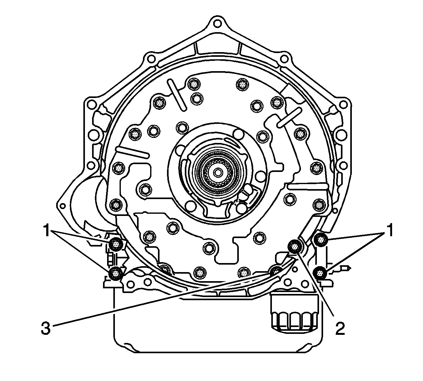
- Remove the closeout plate from the side of the converter housing.
- Remove the lower cooler fitting from the side of the transmission. This is necessary for accessing the lower converter housing to transmission attaching bolt.
- Looking into and around the outside of the converter housing, you will find thirty (30) bolt heads. One at a time, loosen all these bolts about one turn. They were tightened to 54 N·m (40 lb ft).
- Remove the twenty outermost converter housing to transmission bolts.
- Lift the converter housing and front pump assembly from the transmission.
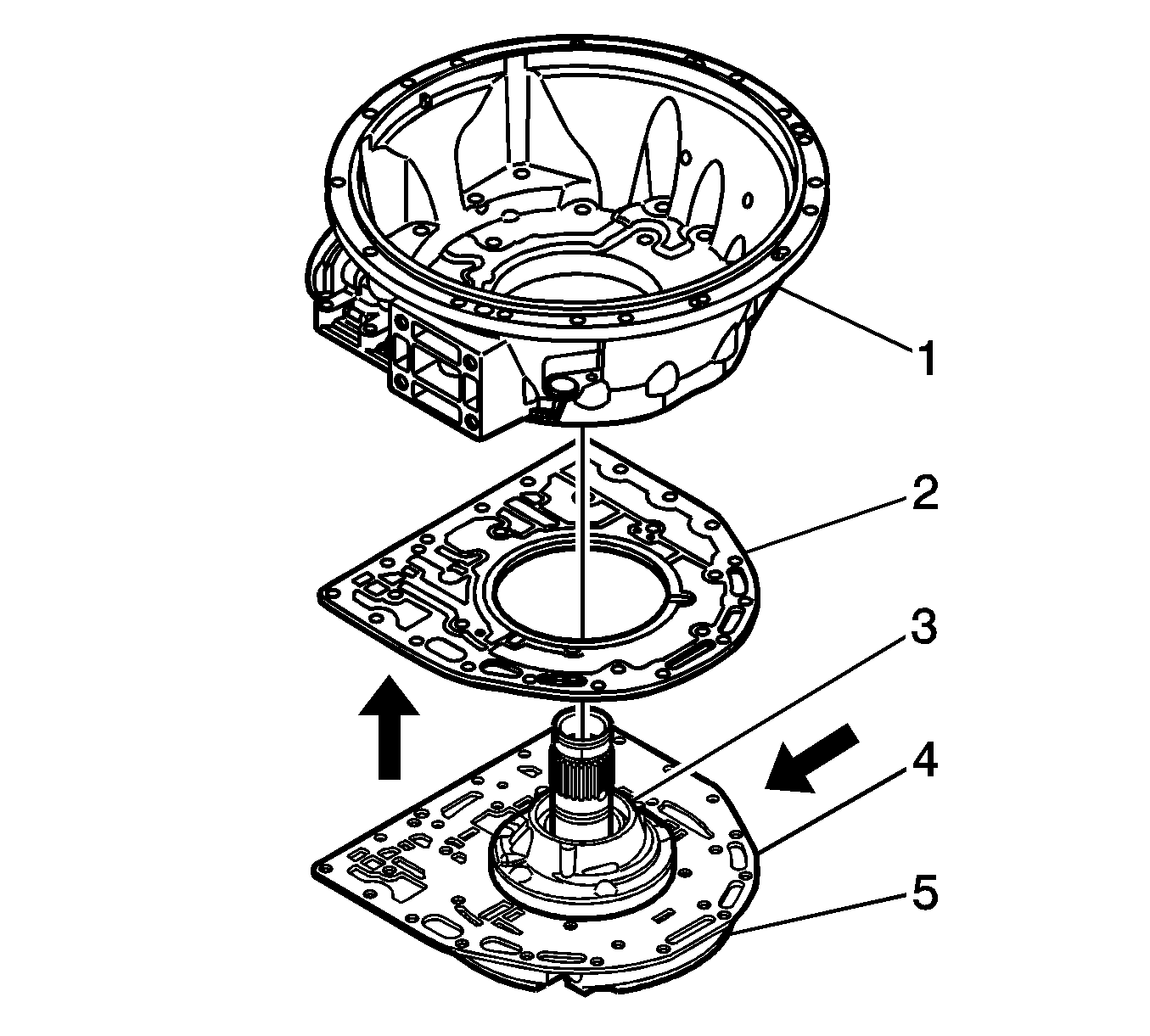
- Remove and discard the housing to separator plate GASKET (3).
- Place the converter housing and front pump assembly on a clean work area.
- Remove the front pump input seal and discard the seal.
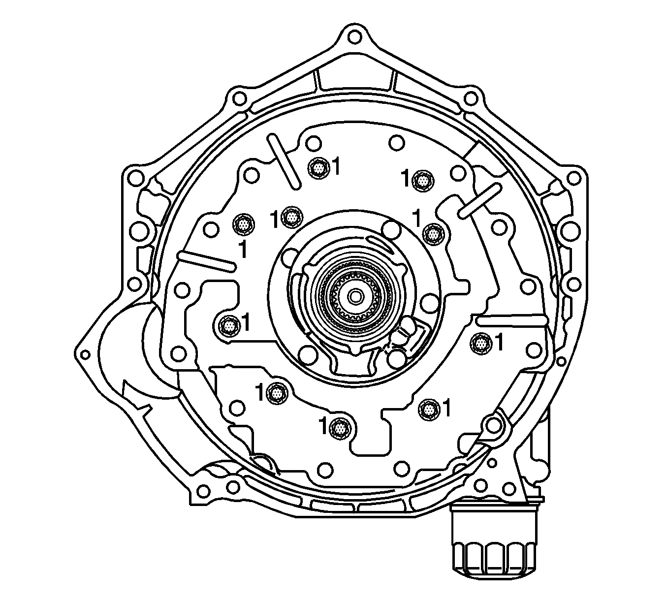
- Remove the inner ring of ten (10) bolts (1) from the converter housing.
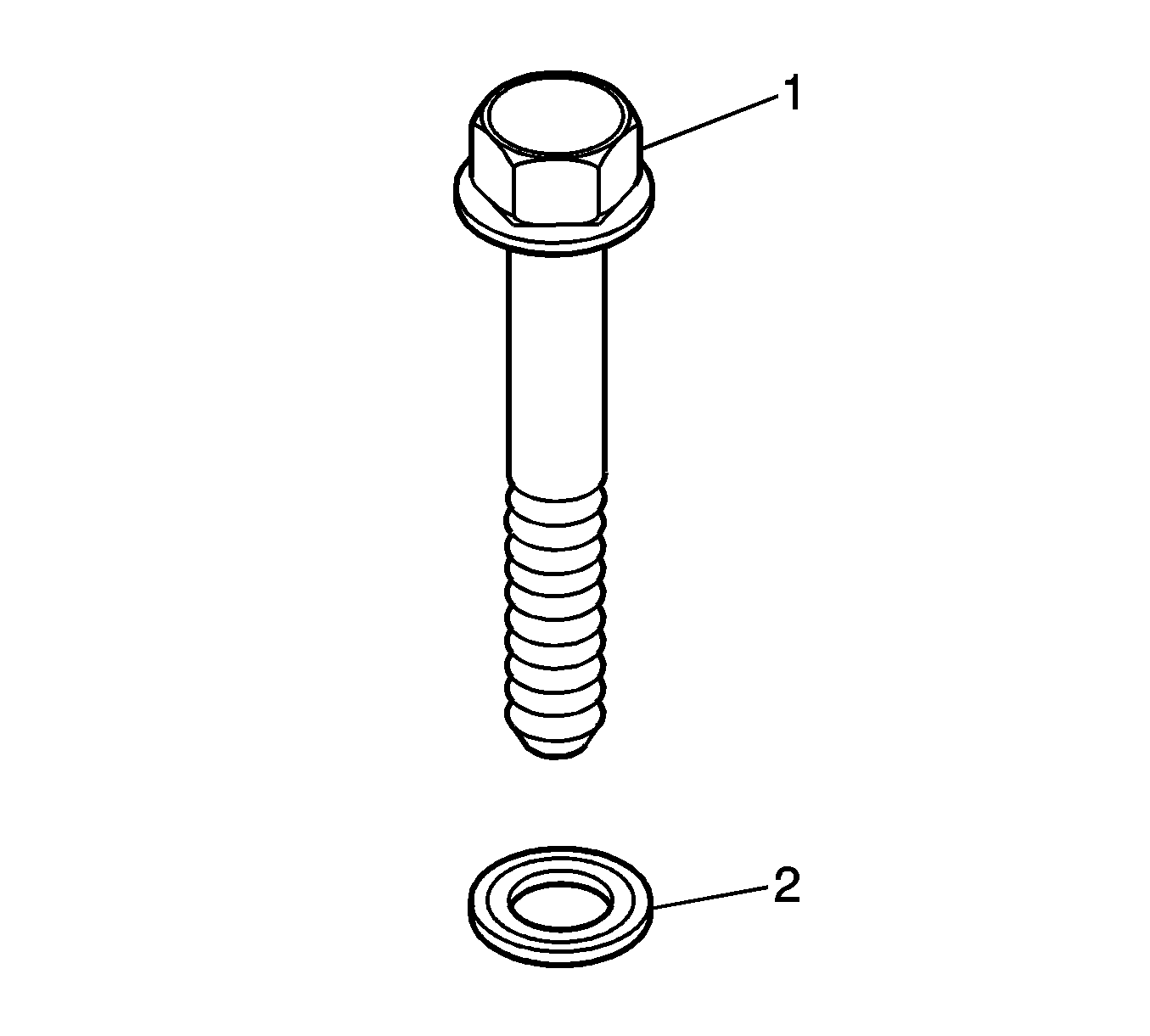
- Remove and discard the seals (2) from under the heads of the ten (10) bolts (1) you just removed.
- Using a wooden block or hammer handle and another hammer, separate the front support and pump from the housing by placing the wooden block or hammer handle on the bosses of the front pump/support module and tapping on the wooden block or hammer, alternating from position to position in a star pattern.
- Remove the two seal rings (1 and 2) from the ground sleeve and the three seal rings (6) and thrust washer (5) from the rear hub of the support assembly.
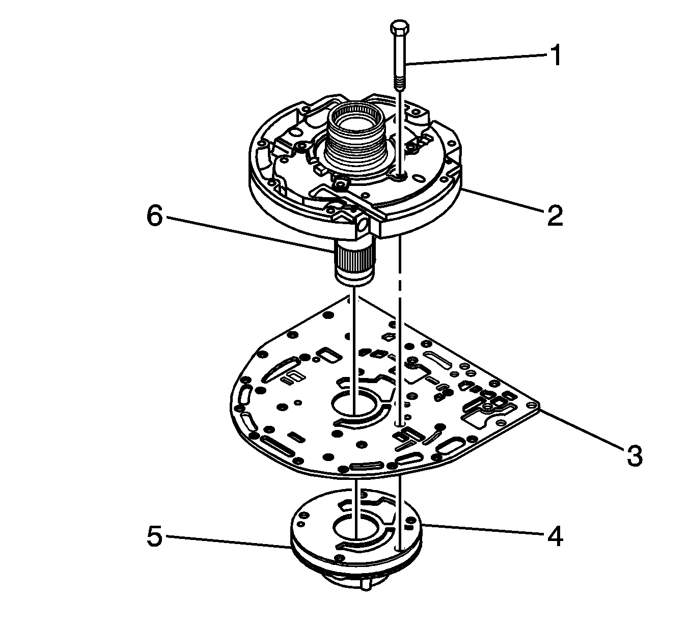
- Remove the five bolts (1) that retain the pump assembly to the front support assembly (2).
- Carefully lift the front support assembly (2) and the separator plate (3) from the oil pump assembly (5).
- Carefully remove the oil pump cover (1) and inspect the drive gear (2) and driven gear (3) for the orientation of the pump gears and the associated punch marks. This is a safety step so that if the cover is separated from the pump, the pump gears may be reinstalled in the same orientation as when the transmission was originally assembled. Otherwise, a noise condition may be encountered after reassembly.
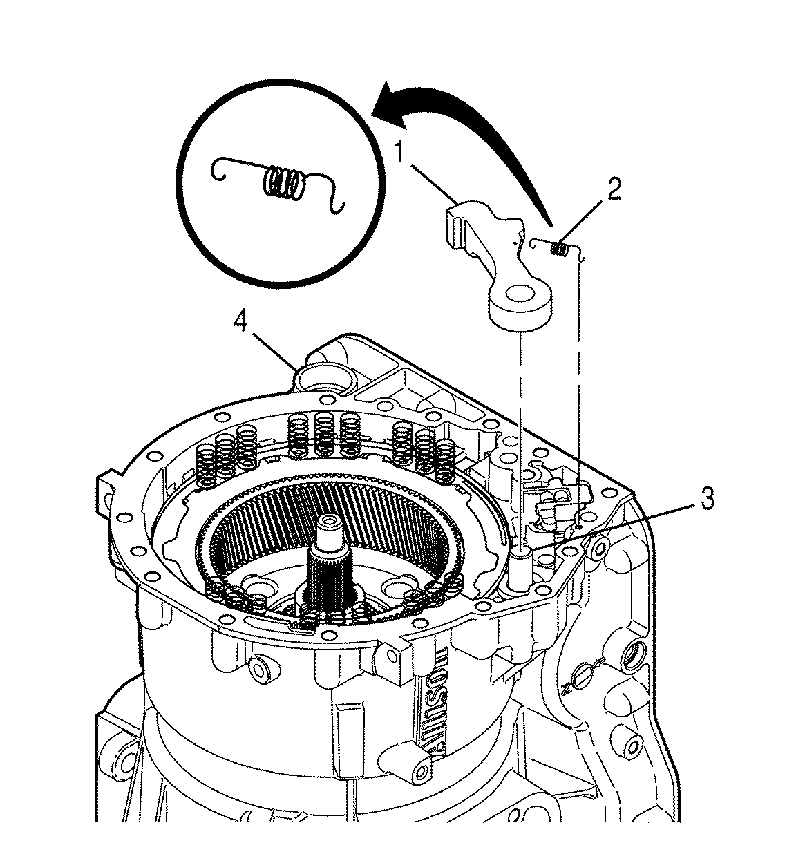
- With the ground sleeve facing up and the support assembly turned so the area without visible oil passages is on the top left, a notch should be seen at the lower left portion of the support assembly. Compress the lube regulator spring to enable removal of the retaining pin (1). The following items are to be removed.
- Insert the J 43773 (2) into the bore you just removed the above components from. Compress the converter relief valve spring enough to remove the "U" shaped retaining clip (1) and remove the clip. Then remove the following items.
- Position the support assembly so that the converter relief valve/lube regulator bore is facing upward. Then install the following components.
- Use the J 43773 tool (2) to compress the spring. Install the retaining clip (1). Ensure that the clip is below the surface of the support.
- Remove the J 43773 tool.
- Install the lube regulator valve (1) as shown above.
- Install the lube regulator spring (2) (blue in color, free length 31.43 mm (1.237 in)).
- Install a new O-ring seal (3) on the lube regulator spring stop (4). Dip the lube regulator spring stop in transmission fluid. Install the stop into the bore. Compress the lube regulator spring/stop and install the retaining pin. Ensure that the pin is below the surface of the support and the stop is positioned against the stop pin.
- With the pump assembly (5) largest diameter facing upward, install the separator plate (3) to the pump with the dowel pins of the pump body ensuring proper alignment of the separator plate.
- Position the support assembly (2) to the pump, aligning the dowel pins. Insert the retaining bolts (1) finger tight.
- Using the star pattern, tighten the five bolts.
- Replace the pump outer O-ring seal (6).
- Place a thin coating of TransJel™, or equivalent, to the flange of the support assembly and the thrust washer. Then install the thrust washer, properly aligning the retaining tabs.
- Install three new seal rings (6) with the correct part number to the hub of the support assembly.
- Turn the pump and support assembly over and install one P/N 29536406 (2) into the middle groove of the ground sleeve (3).
- Install one P/N 29536405 (1) seal ring into the top groove of the ground sleeve (3).
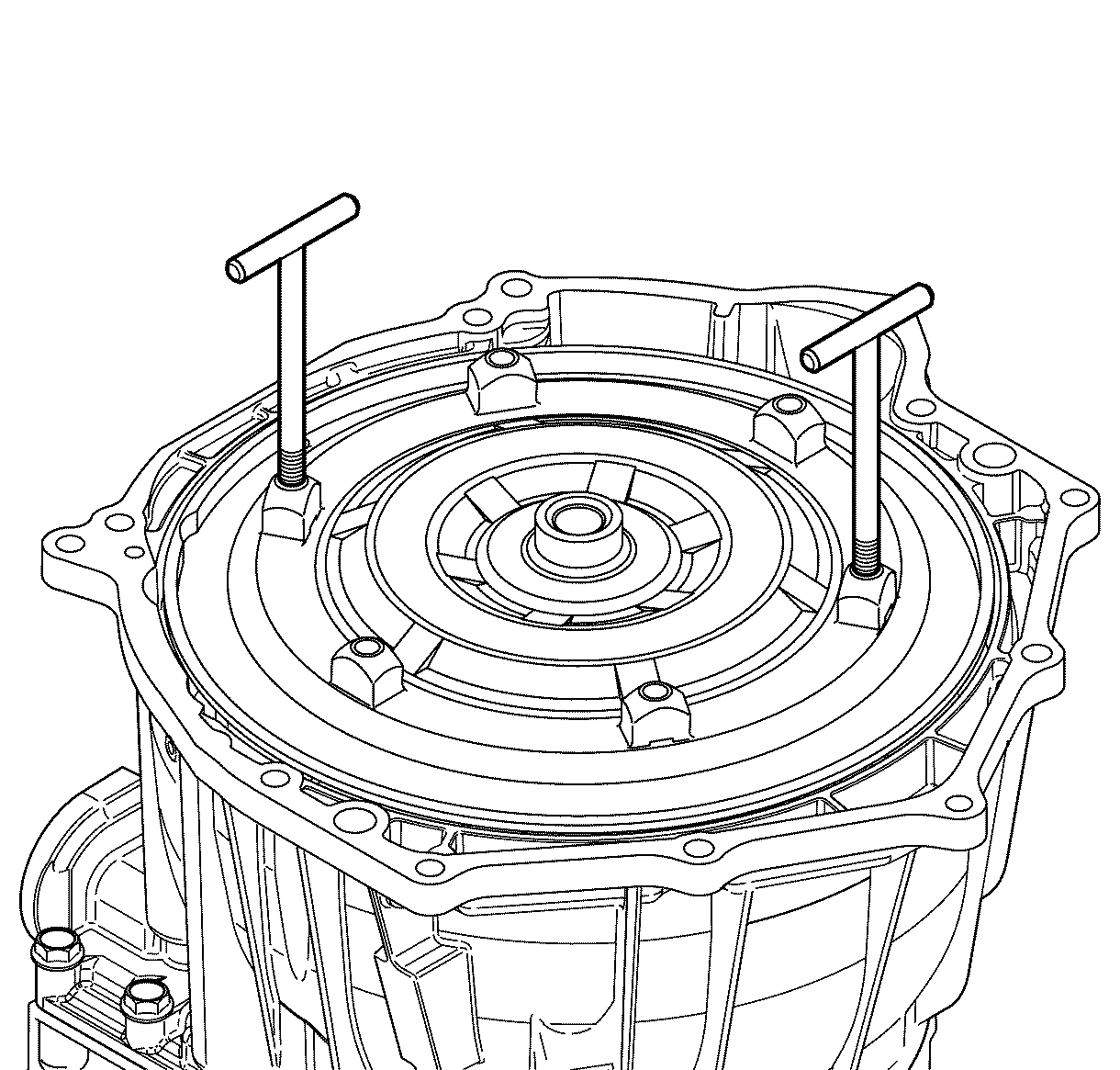
- Place two guide pins (2) into the support assembly so the spacer plate gasket and converter housing may be assembled .
- Position the spacer plate gasket (2) and converter housing (1) to the pump/support assembly (3).
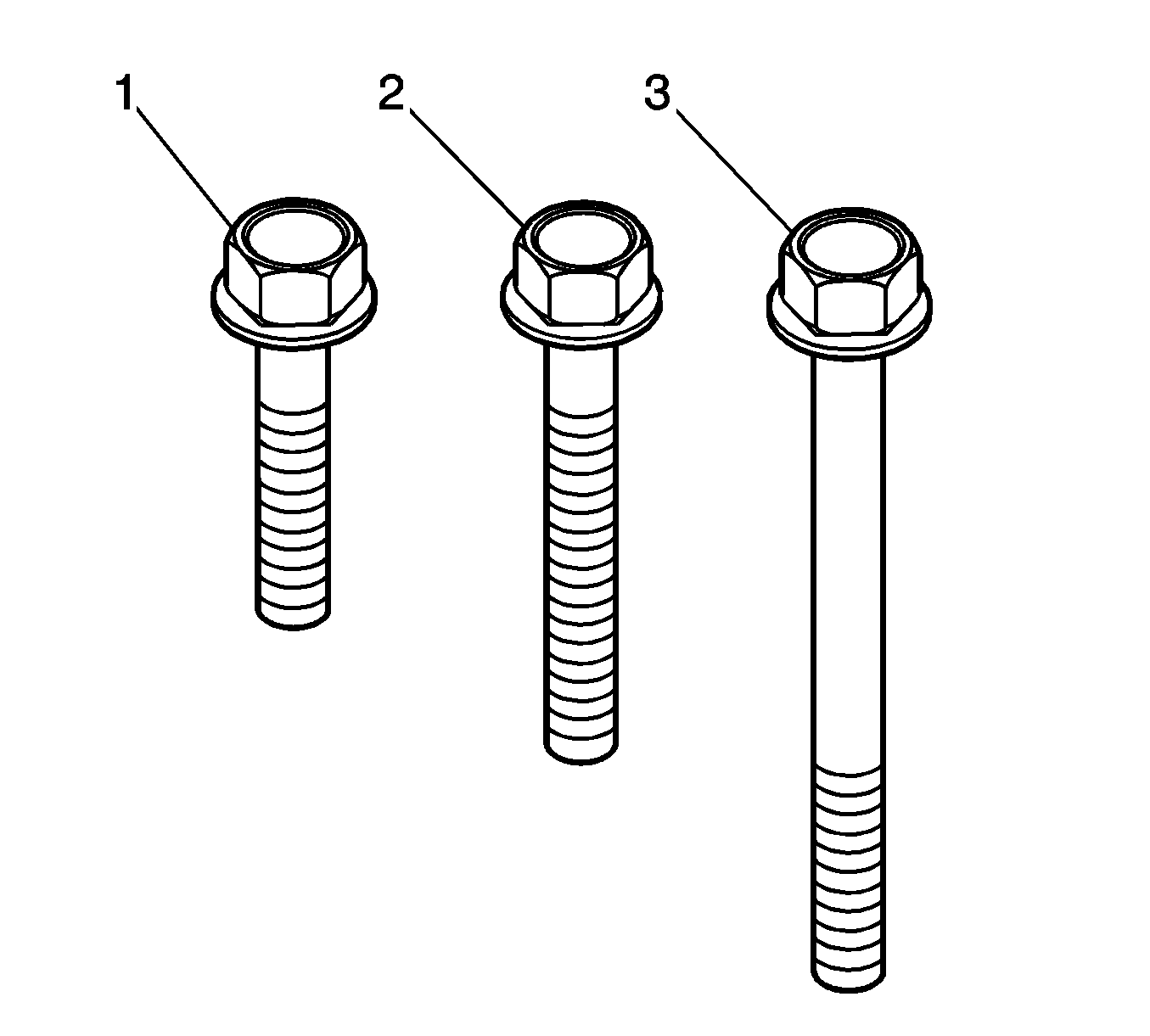
- Install new bolt seals (2) to the ten short bolts (1).
- Install eight of the short bolts into the locations marked with the (1). Tighten the bolts finger tight. Then snug the bolts with a socket. The bolts will be tightened to final torque later.
- Remove the guide pins.
- Install two of the short bolts into the locations where the guide pins were located. Tighten the bolts finger tight. Then snug the bolts with a socket. The bolts will be tightened to final torque later.
- Install the guide pins into a couple of the transmission bolt holes.
- Place the main housing gasket into position over the guide pins onto the transmission case assembly.
- Place the transmission converter housing, pump assembly, and support (1) into position on the transmission assembly.
- Place the remaining bolts into position as shown, paying particular attention to the bolt numbers and locations. Install all bolts finger tight. Then tighten all thirty of the bolts to the appropriate specification.
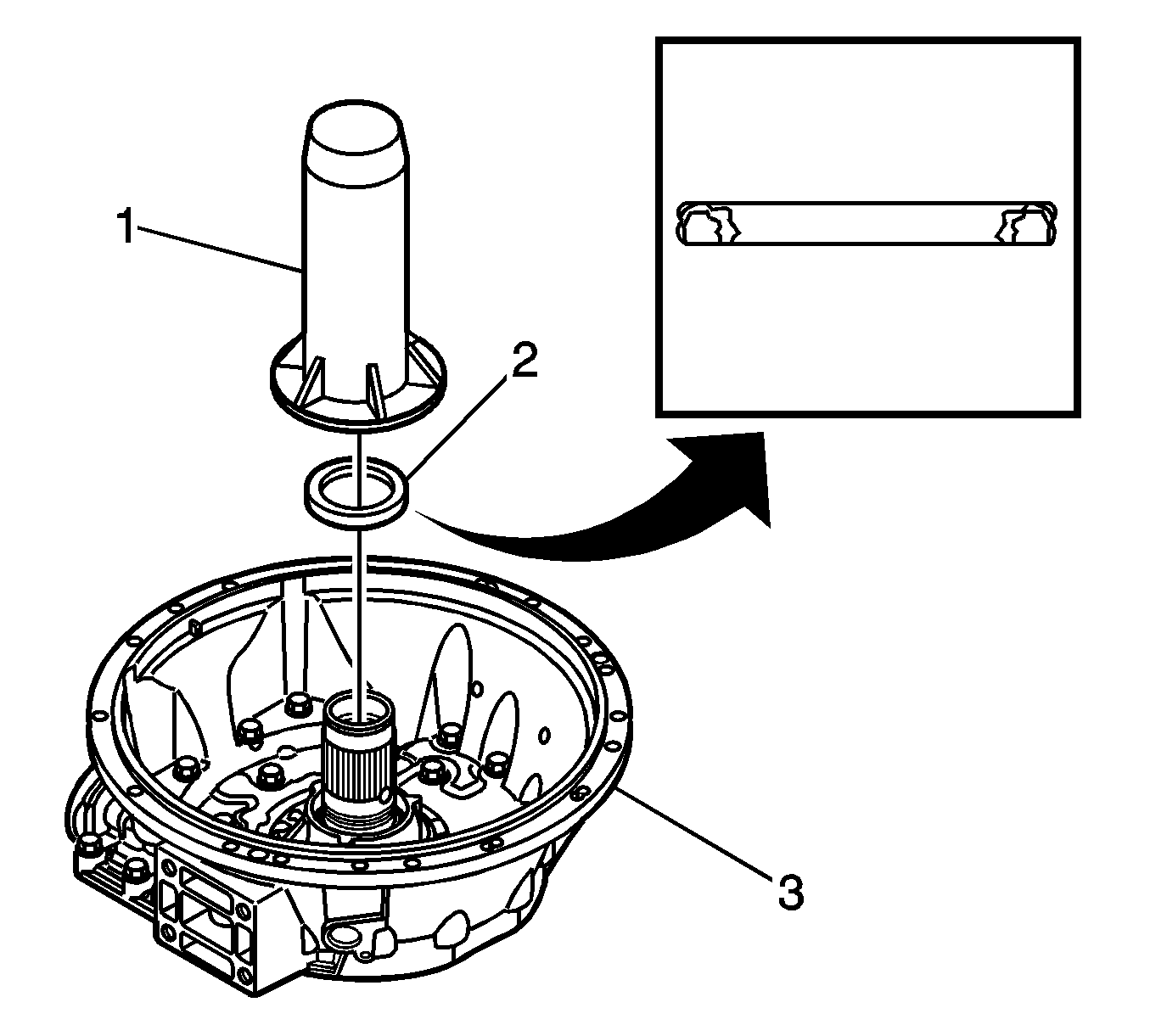
- Install the seal (2) into the oil pump hub with the J 43772.
- Install a new transmission suction filter, P/N 29537965.
- Install the transmission oil pan and gasket.
- Remove the transmission control main filter and do not reuse.
- Install a new control main filter, P/N 29539579.
- Install the torque converter to the transmission assembly.
- Remove the J 46409 - Torque Converter Lifting Tool.
- Install the J 21366 - Converter Holding Strap.
- Using the transmission transfer lift, transfer the transmission from the engine stand to the transmission jack.
- Remove the J 44723 - Transmission Support Fixture.
- Using new PTO cover gaskets, reinstall the PTO covers.
- Reinstall the cooler line adapter.
- Reinstall the inspection cover.
- Install the extension housing to transfer case gasket.
- Flush the transmission oil cooler. Refer to Automatic Transmission Oil Cooler Flush and Flow Test Essential Tool J 45096 Transflow® in Corporate Bulletin Number 02-07-30-052C (SI Document ID# 1547813).
- For transmission installation procedures, refer to the proper Service Information Document listed below.
- AFTER COMPLETION OF THE TRANSMISSION INSTALLATION, DIAGNOSE AND REPAIR THE CAUSE OF THE DRIVELINE IMBALANCE.
Caution: The Allison® 1000 Series (M74) torque converter has a dry weight of approximately 29 kg (63 lbs). Use caution when handling to avoid personal injury.
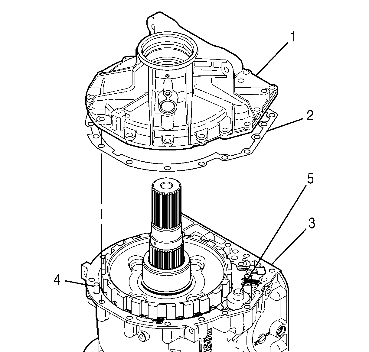
Important: When removing the rear extension housing, it is possible for the park pawl support pin to be removed with the rear extension housing.

Tighten
Tighten all 16 of the rear extension housing bolts to 56 N·m (42 lb ft).
Notice: The next step is determining the critical end play measurement within the transmission. Failure to follow the procedure may cause internal failure of the transmission.
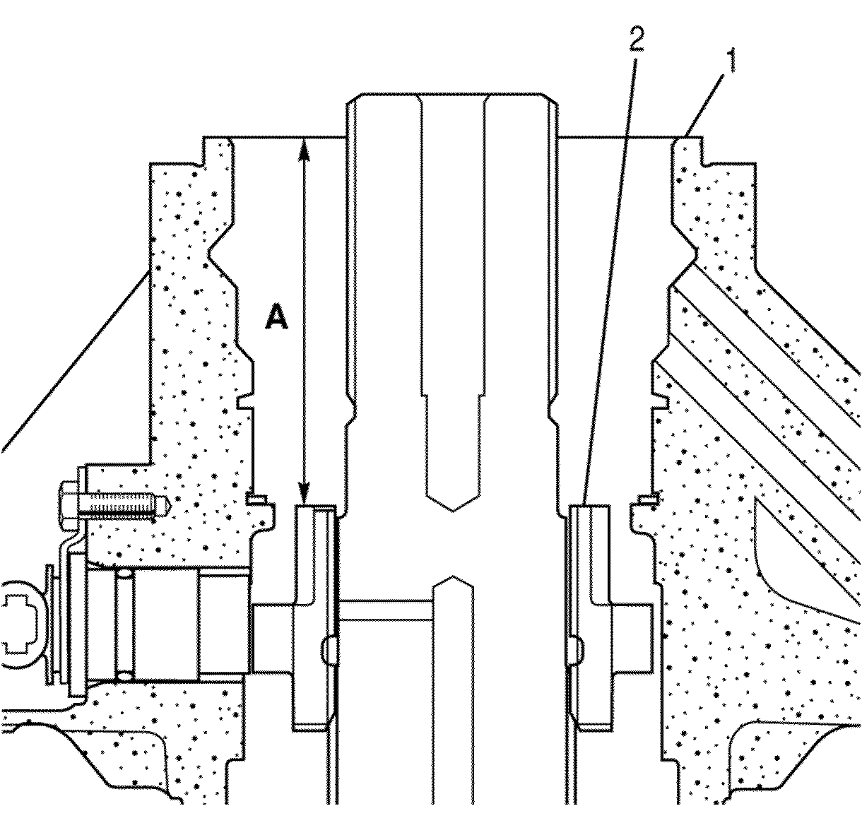
| • | Look at the bearing spacer located on the output shaft. You will notice a flat with two half-moon shaped slots 180° apart. Measure the distance from the case flange (1) to this surface (2). Be sure not to make your measurement in the slot. This is Dimension A. |
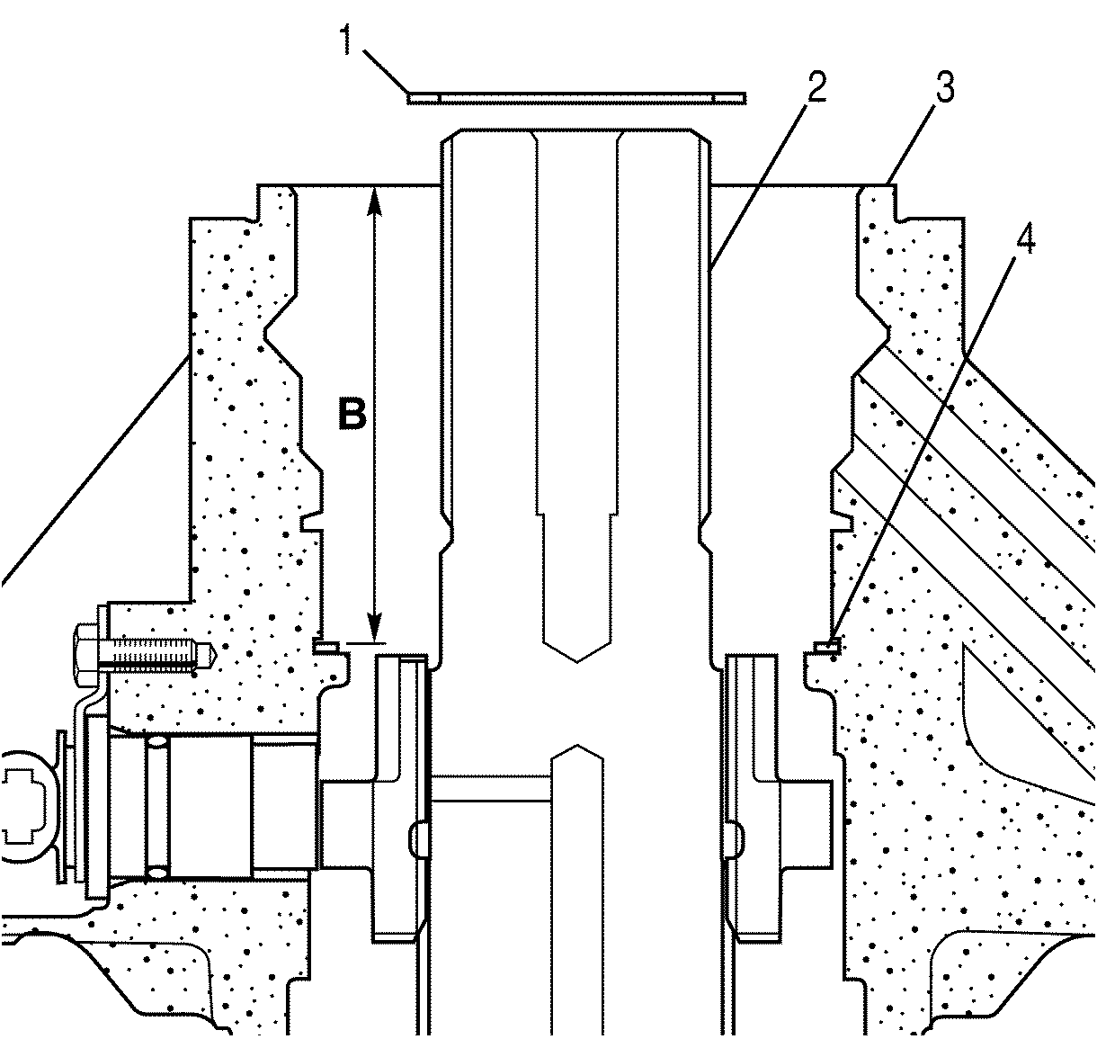
| • | Look into the extension housing. Notice the snap ring installed around the outside of the inner diameter (4). Dimension B is from the top surface of this snap ring to the case flange (3). |
| • | Subtracting Dimension B from Dimension A gives Dimension C. With Dimension C known, you will determine which selective spacer to install in the transmission. See the table at the end of this procedure. |
Important: The used ball bearing assembly removed from the extension housing previously will be TEMPORARILY installed into the new extension housing assembly to allow for the critical end play measurement. This ball bearing assembly must be replaced with the new ball bearing assembly after the end play has been determined to be within the allowable range.
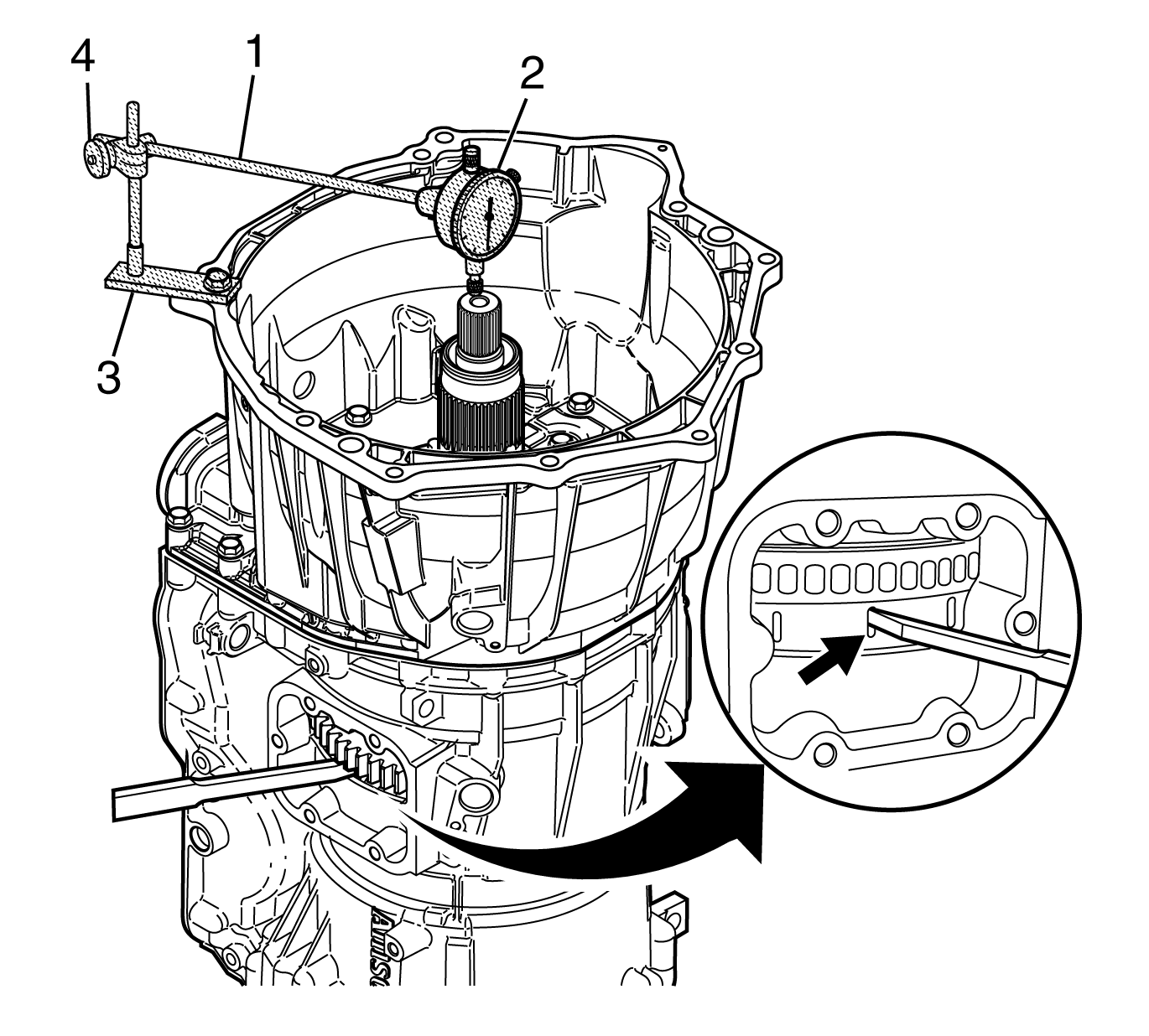
Important: The end play measurement must be between 0.279 - 1.549 mm (0.0110 - 0.0610 in).
Important: The used ball bearing assembly must be removed from the extension housing and replaced with a new bearing. Using the puller to remove the original bearing may have damaged the race of the bearing. A new ball bearing assembly must be installed any time the puller is used on this bearing.

Tighten
Tighten the output nut (2) to 61 N·m (45 lb ft).
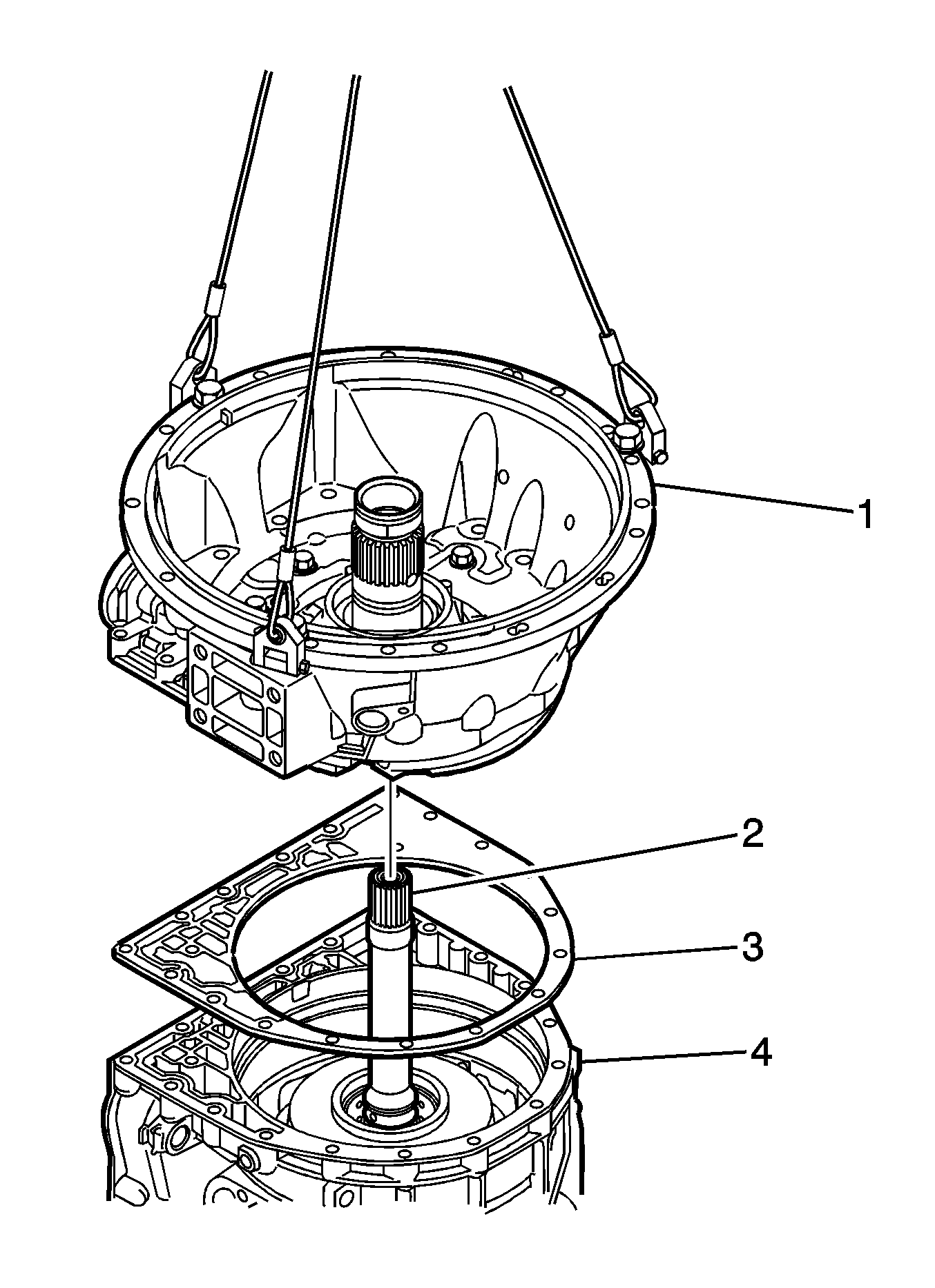
Caution: The converter housing and front pump assembly has a dry weight of approximately 27 kg (60 lb). Use caution when lifting the converter housing in order to prevent personal injury.
Notice: Use care so damage to the separator plate is not incurred when separating the front support and pump assembly from the converter housing or when separating the front support from the pump assembly.
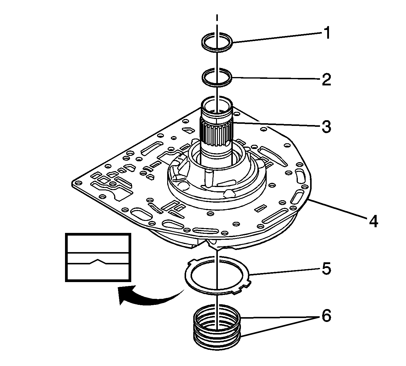
Important: The seal rings (6) may be either a butt-type or an overlap style. The service kit comes with both types. Replace the seal rings with the same type as those removed.
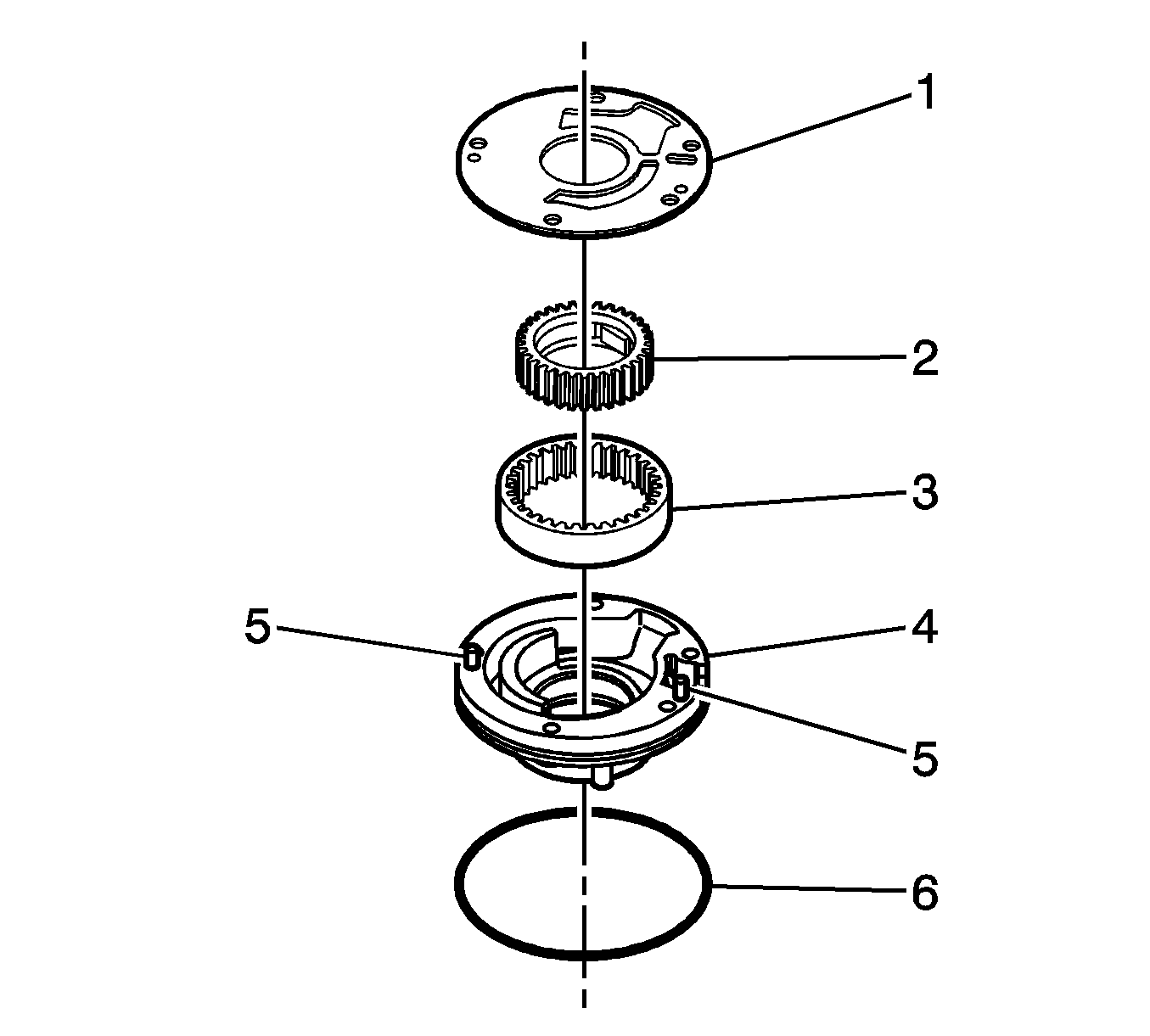
Important: The oil pump drive and driven gears have a punch mark on one side. Before the gears are removed from the pump, inspect the drive and driven gears for the location of the punch mark. The oil pump gears should be reassembled in this same orientation as removed.
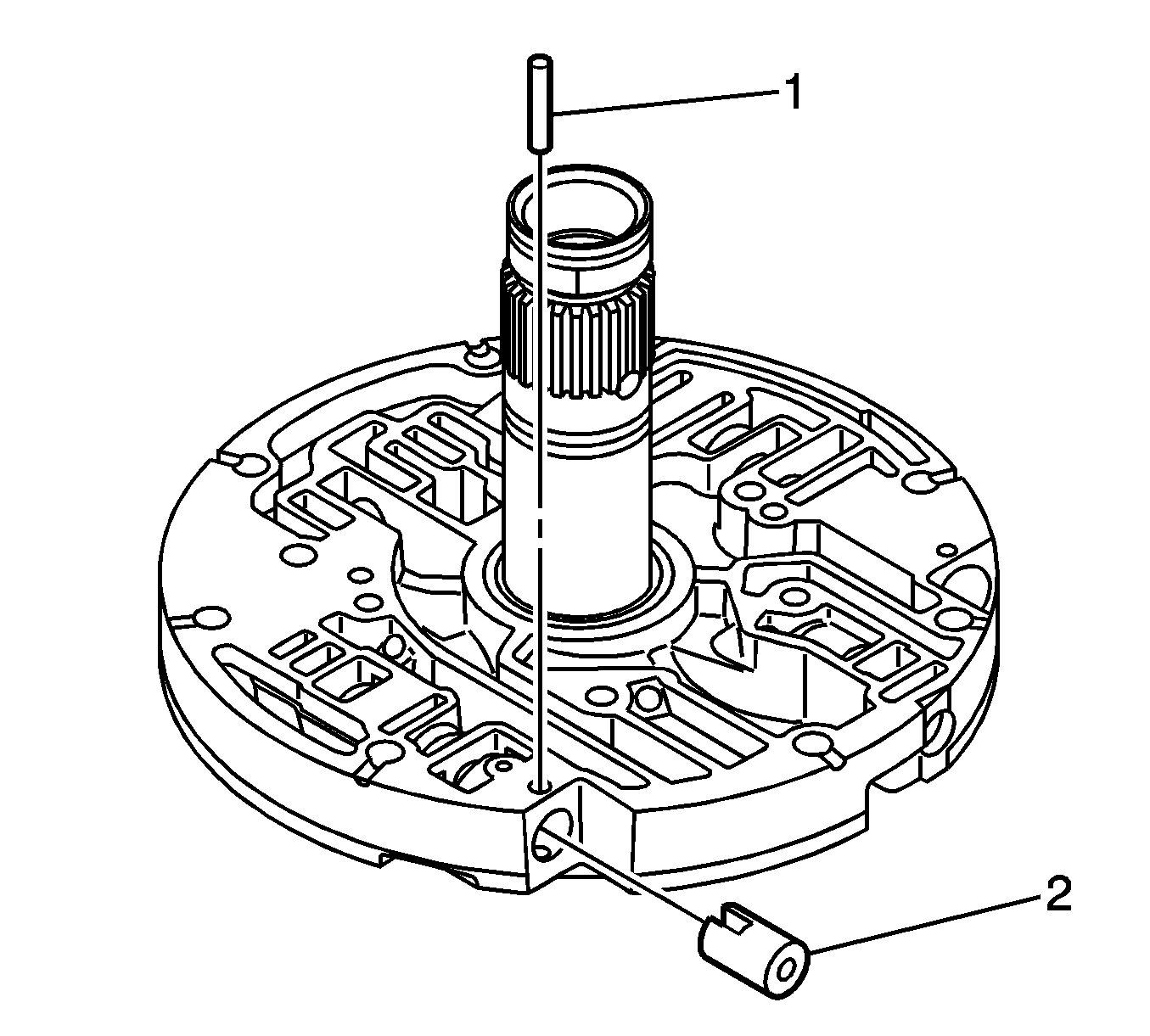
Important: You will need to note the proper orientation of the two springs and the two valves. The replacement springs must be installed exactly like the removed component or transmission failures and/or shift conditions will occur.
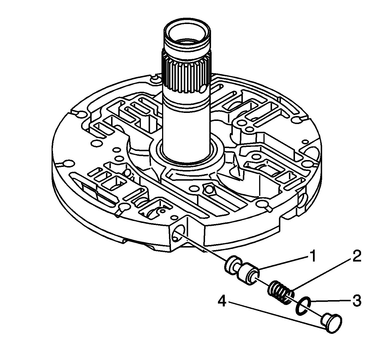
| • | The retaining pin |
| • | The stop (4) with O-ring seal (3) (remove and discard the O-ring seal) |
| • | A short spring (2) |
| • | The lube regulator valve (1) |
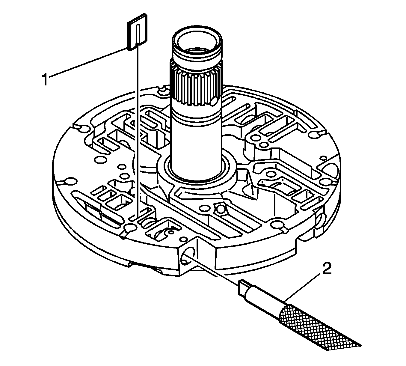
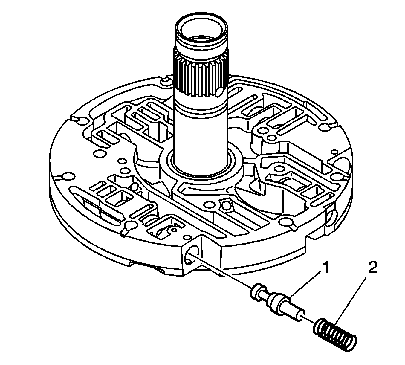
| • | The converter relief spring (2) |
| • | The converter relief valve (1) |
Notice: Transmission damage may occur when springs and other parts are mistakenly interchanged. Proper springs and other part identification is very important.
| • | The converter relief valve (1) (big end first, the small end fits into the converter relief spring) |
| • | The converter relief spring (2) (Natural steel, no color, free length 44.85 mm (1.766 in)) |


Important: If the lube regulator stop O-ring seal is cut or omitted, the transmission will not prime.

Tighten
Tighten the five bolts to 24-29 N·m (18-21 lb ft).


Notice: Interchanging the ground sleeve sealing rings with the wrong part number seal ring on the ground sleeve (stator shaft) may result in transmission damage. Install the correct seal ring.
Important: The seal rings (6) may be either a butt-type or an overlap style. The service kit comes with both types. Replace the seal rings with the same type as those removed.
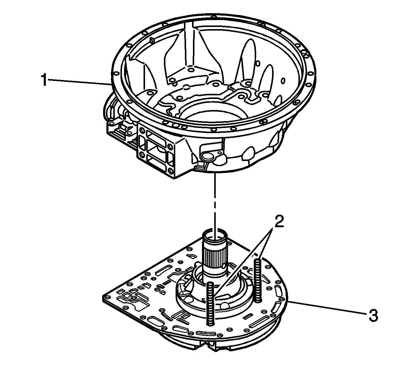



Tighten
Tighten all bolts to 55 N·m (40 lb ft).
Tighten
Tighten to 27 N·m (20 lb ft).
Tighten
Tighten ONE FULL TURN after the filter seal contacts the case.
Notice: Ensure that the converter housing (bellhousing) opening is pointing upward or the pump seal may be damaged when the converter is placed into position.

Tighten
Tighten the bolts to 55 N·m (40 lb ft).
| • | For vehicles equipped with the Duramax™ Diesel (LB7), refer to Document ID #758397. |
| • | For vehicles equipped with the 8.1L gas engine (L18), refer to Document ID #758399. |
Important:
• Be sure that the transmission fluid level is in "COLD" range before shifting out of Park. • After completing this modification, the transmission control module (TCM) shift adapts must be relearned for proper transmission operation. For MY 2001 using the Tech 2®, select Special Functions (F2), Transmission Output Controls (F1),
Preset All Tap Cells, Disconnect the Tech 2®. This action will reset all clutch adaptives and requires the vehicle to be driven. For MYs 2002-2004, follow the procedure outlined in Corporate Bulletin Number 02-07-30-032A to quickly relearn the
transmission shift adapts.
If Dimension C Equals | Use spacer with this # of Identifier Holes | Spacers Thickness |
|---|---|---|
1.0081-1.1844 mm (0.0397-0.0466 in) | 0 | 0.245-0.295 mm (0.0096-0.0116 in) |
10185-1.414 mm (0.0467-0.0557 in) | 1 | 0.475-0.525 mm (0.0187-0.0207 in) |
1.415-1.644 mm (0.0557-0.0647 in) | 2 | 0.705-0.755 mm (0.0278-0.0297 in) |
1.645-1.874 mm (0.0648-0.0738 in) | 3 | 0.935-0.985 mm (0.0368-0.0388 in) |
1.875-2.104 mm (0.0738-0.0828 in) | 4 | 1.165-1.215 mm (0.0459-0.0478 in) |
2.105-2.334 mm (0.0829-0.0919 in) | 5 | 1.395-1.445 mm (0.0549-0.0569 in) |
2.335-2.5015 mm (0.0919-0.0988 in) | 6 | 1.625-1.675 mm (0.0640-0.0659 in) |
Parts Information
Part Number | Description | Qty |
|---|---|---|
29541378 | Sub Assy, Extension Housing | 1 |
23047970 | Output Bearing | 1 |
29531231 | Output Nut | 1 |
29536941 | Gasket | 1 |
29536981 | Snap ring | 1 |
29536407 | Kit: Shim Selective | 1 |
29531147 | Spring, Pawl Return | 1 |
29531325 | Gasket, PTO cover | 1 |
15704050 | Gasket, Transmission to Transfer Case. | 1 |
88996718 | Kit, Torque Converter Drain-back Modification | 1 |
29537965 | Filter, Transmission Oil Pan | 1 |
29539579 | Filter, Transmission Spin-on | 1 |
12378470 (1 quart) (in Canada, 1 L, P/N 10952622) | DEXRON® III Automatic Transmission Fluid | 12 L (13 quarts) |
Warranty Information
For vehicles repaired under warranty, use:
Labor Operation | Description | Labor Time |
|---|---|---|
K6390 | Transmission Housing and/or Housing to Case Seal or Gasket Extension - Replace | |
with 6.6L Diesel Engine and Two Wheel Drive (2WD) | 4.9 hrs | |
with 6.6L Diesel Engine and Four Wheel Drive (4WD) | 5.3 hrs | |
with 8.1L Gasoline Engine and Two Wheel Drive (2WD) | 4.5 hrs | |
with 8.1L Gasoline Engine and Four Wheel Drive (4WD) | 5.0 hrs | |
Add | Diagnostic Time | 0.0-0.5 hr |
Add | To Clean Parts Over 48,000 km (30,000 mi) | 0.1-0.3 hr |
Add | with Driveshaft Center Support | 0.3 hr |
Add D | with Skid Plates | 0.3 hr |
