Allison Transmission Delayed Engagement, Cold Hesitation, Malfunction Indicator Lamp (MIL) Illuminated, DTCs P0701, P1709, P1711, P1713, P0841, P0843, P0847, P0870, P0872 or P0875

| Subject: | Allison Transmission Delayed Engagement, Cold Hesitation, Malfunction Indicator Lamp (MIL) Illuminated, DTCs P0701, P1709, P1711, P1713, P0841, P0843, P0847, P0870, P0872, or P0875 (Replace Torque Converter Relief Spring, Transmission Fluid Indicator and Lube Regulator Spring in Front Support) |
| Models: | 2001-2003 Chevrolet Silverado 2500/3500 Series |
| 2001-2003 GMC Sierra 2500/3500 Series |
| with Allison® 1000 Series Automatic Transmission (RPO M74) |
| Built Prior to Indianapolis Plant Serial Number 6310234829, Baltimore Plant Serial Number 6320154492 and Remanufactured Transmission Serial Number 9620011913 |
This bulletin is being revised to change the automatic transmission fluid to use from DEXRON®-III to DEXRON®-VI and change the Warranty Labor Time information. Please discard Corporate Bulletin Number 03-07-30-011D (Section 07 -- Transmission/Transaxle).
Condition
Some customers may comment that the transmission has a delayed engagement, cold hesitation or may illuminate the MIL on the first start-up after sitting for a period of time.
Cause
Torque converter bleed down over an extended period of non-usage, usually over a week, may cause this condition.
Correction
Use the service procedure shown below to access and change the torque converter relief spring and lube regulator spring in the front support assembly. Installation of these parts will not eliminate the torque converter bleed down or a potential delayed engagement. These parts will prevent transmission DTCs and their resulting default actions associated with an extended period of non-usage.
Important:
• A vented transmission fluid level indicator, P/N 15115171, should be installed after the transmission has been reinstalled. This vented indicator will help to prevent fluid leaks out of the vent in cold weather operation. For additional information
on this vented transmission fluid indicator, refer to Corporate Bulletin Number 03-07-30-054 (SI Document ID #1397788). • After completing this modification, the transmission control module (TCM) shift adapts must be relearned for proper transmission operation. Follow the procedure outlined in Corporate Bulletin Number 02-07-30-032A (SI Document ID #1198957)
to quickly relearn the transmission shift adapts. Note that the fast learn procedure is not available for 2001 model year vehicles.
Caution:
• The Allison® 1000 Series (M74) transmission has a dry weight of approximately 150 kg (330 lbs). The torque converter has a dry weight of approximately 29 kg (63 lbs). • Use caution when removing, installing, servicing or moving the transmission in order to prevent personal injury. • Get assistance when lifting the transmission. A hoist is the preferred lifting device. Ensure that the lifting device is adequate to support the transmission.
- Remove the transmission from the vehicle. For transmission removal, refer to the proper Service Information Document listed below. After removal, return to this document for the transmission modification procedure.
- Install the transmission holding fixture. Refer to Unit Repair -- Holding Fixture Installation -- SI Document ID# 1209038.
- Remove the torque converter. Refer to Unit Repair -- Torque Converter Assembly Removal -- SI Document ID# 1209089.
- Remove the torque converter housing / pump assembly. Refer to Unit Repair -- Torque Converter Housing/Pump Assembly Removal -- SI Document ID# 1209092.
- Remove the torque converter housing from the pump assembly. Refer to Unit Repair -- Torque Converter Housing from Pump Assembly Disassemble -- SI Document ID# 1209112.
- Disassemble the main oil pump. Refer to Unit Repair -- Main Pump Disassemble -- SI Document ID# 1209119.
- Inspect the main oil pump. Refer to Unit Repair -- Main Pump Inspection -- SI Document ID# 1442222.
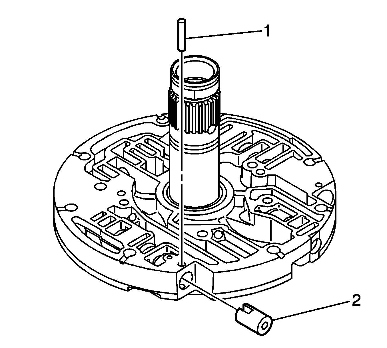
- With the ground sleeve facing up and the support assembly turned so the area without visible oil passages is on the top right, a notch should be seen at the upper left portion of the support assembly. With the aid of the J 43773 (2), compress the lube regulator spring to enable removal of the retaining pin (1). The following items are to be removed.
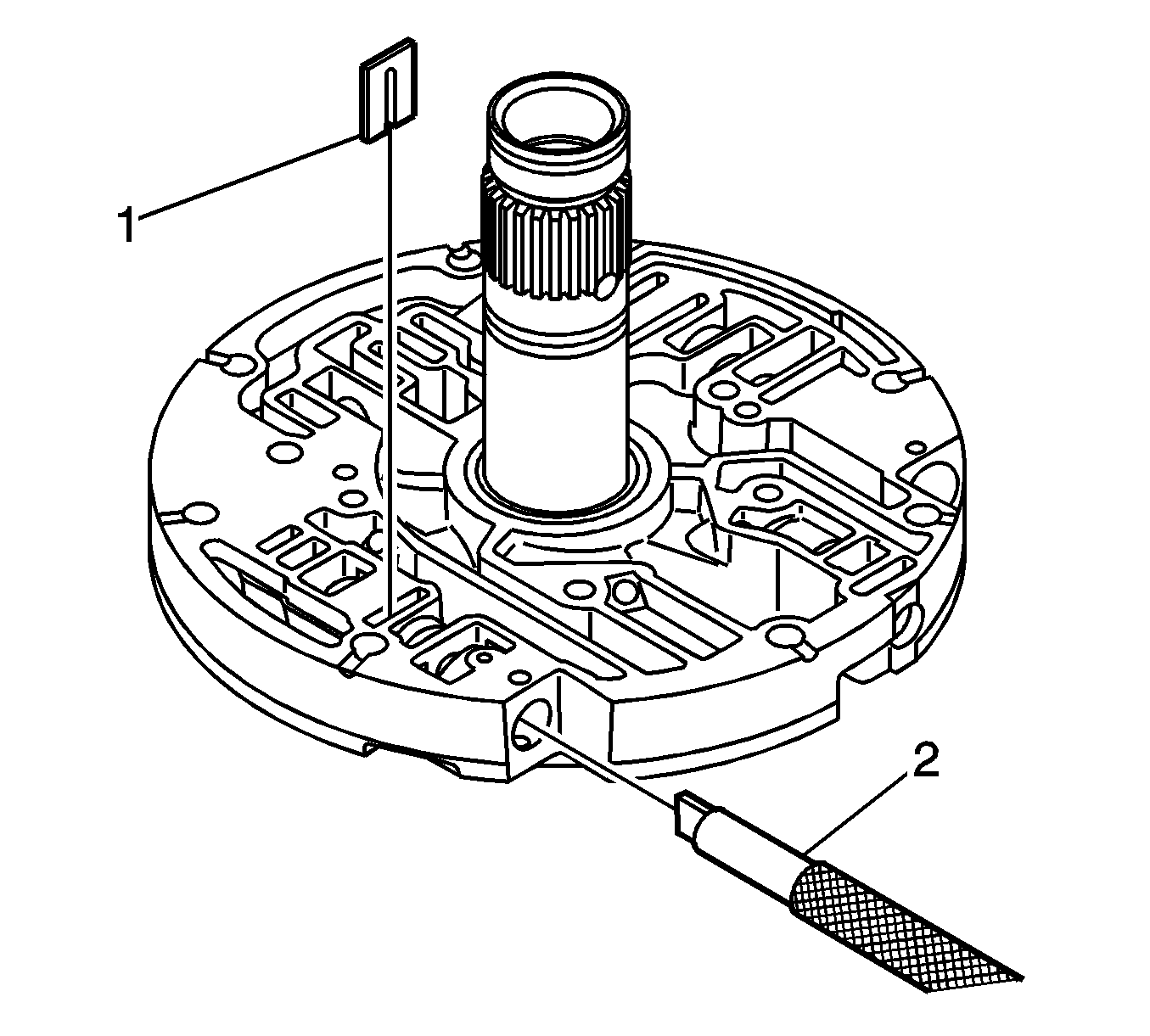
- Insert the J 43773 (2) into the bore you just removed the above components from. Compress the converter relief valve spring enough to remove the "U" shaped retaining clip (1) and remove the clip. Then remove the following items.
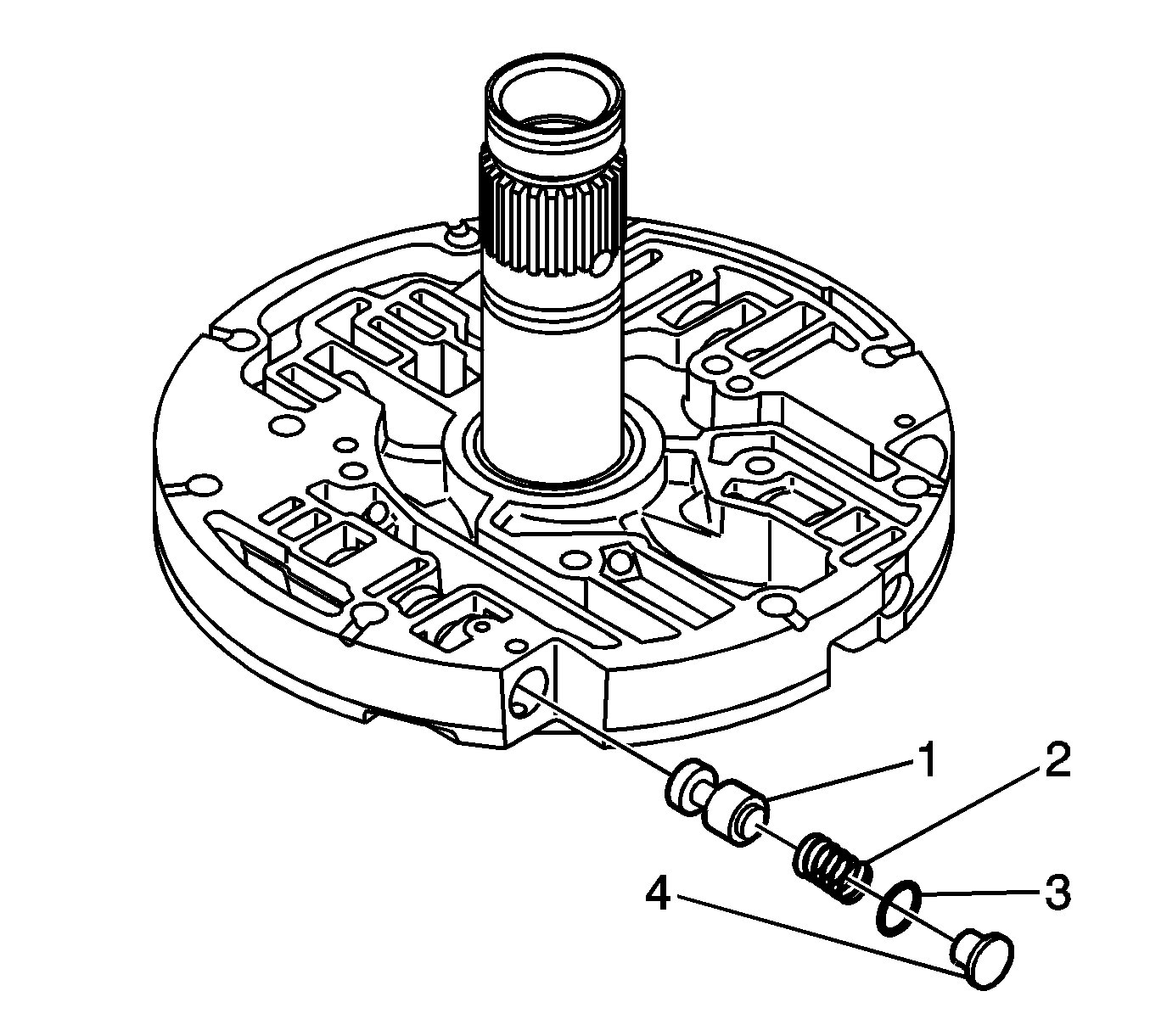
- Position the support assembly so that the converter relief valve/lube regulator bore is facing upward. Then install the following components.
- Use J 43773 tool (2) to compress the spring. Install the retaining clip (1). Ensure that the clip is below the surface of the support.
- Remove the J 43773 tool.
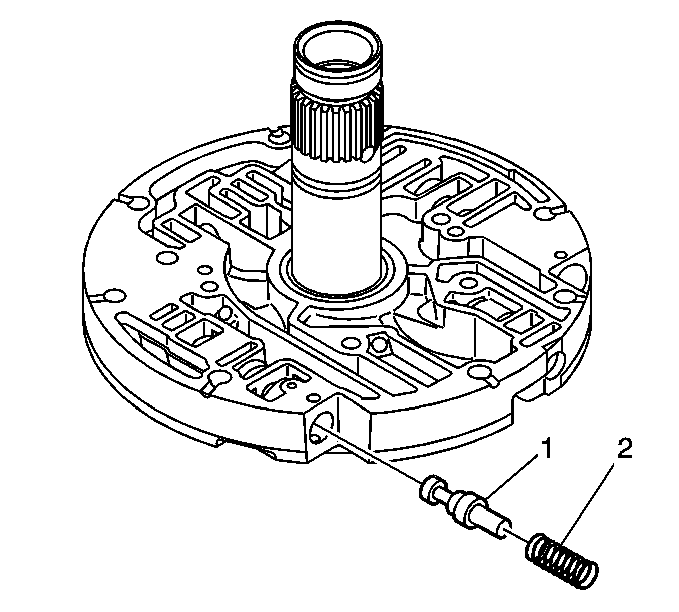
- Install the lube regulator valve (1) as shown above.
- Install the lube regulator spring (2) (blue in color, free length 31.43 mm (1.237 in)).
- Install a new O-ring seal (3) on the lube regulator spring stop (4). Dip the lube regulator spring stop in transmission fluid. Install the stop into the bore. Use the J 43773 tool to compress the spring. Install the retaining pin. Ensure that the pin is below the surface of the support and the stop is positioned against the stop pin.
- Reassemble the main oil pump. Refer to Unit Repair -- Main Pump Assemble -- SI Document ID# 1221915.
- Reassemble the main pump to the torque converter housing. Refer to Unit Repair -- Front Support Assemble -- SI Document ID# 1206991.
- Install the torque converter housing. Refer to Unit Repair -- Torque Converter Housing/Pump Assembly Installation -- SI Document ID# 1209875.
- For transmission installation procedures, refer to the proper Service Information Document listed below.
- Replace the transmission fluid indicator with P/N 15115171.
| • | For vehicles equipped with the Duramax™ Diesel (LB7), refer to Document ID #758397. |
| • | For vehicles equipped with the 8.1L gas engine (L18), refer to Document ID #758399. |

Important: You will need to note the proper orientation of the two springs and the two valves. The replacement springs must be installed exactly like the removed component or transmission failures and/or shift conditions will occur.

| • | The retaining pin |
| • | The stop (4) with O-ring seal (3) (remove and discard the O-ring seal) |
| • | A short spring (2) |
| • | The lube regulator valve (1) |


| • | The converter relief spring (2) |
| • | The converter relief valve (1) |
Notice: Transmission damage may occur when springs and other parts are mistakenly interchanged. Proper springs and other part identification is very important.
| • | The converter relief valve (1) (big end first, the small end fits into the converter relief spring) |
| • | The converter relief spring (2) (Natural steel, no color, free length 44.85 mm (1.766 in)) |


Important: If the lube regulator stop O-ring seal is cut or omitted, the transmission will not prime.
Important:
• A vented transmission fluid level indicator, P/N 15115171, should be installed after the transmission has been reinstalled. This vented indicator will help to prevent fluid leaks out of the vent in cold weather operation. • After completing this modification, the transmission control module (TCM) shift adapts must be relearned for proper transmission operation. Follow the procedure outlined in Corporate Bulletin Number 02-07-30-032 to quickly relearn the transmission
shift adapts. Note that the fast learn procedure is not available for 2001 model year vehicles.
| • | For vehicles equipped with the Duramax™ Diesel (LB7), refer to Document ID #758397. |
| • | For vehicles equipped with the 8.1L gas engine (L18), refer to Document ID #758399. |
Parts Information
Part Number | Description | Qty |
|---|---|---|
88996718 | Kit, Torque Converter Drain-back Modification | 1 |
88861003 (1 quart) (Canadian P/N 88861004(1L)) | DEXRON®-VI Automatic Transmission Fluid | 12 L (13 quarts) |
15115171 | Indicator, Transmission Fluid | 1 |
Warranty Information
For vehicles repaired under warranty, use:
Labor Operation | Description | Labor Time |
|---|---|---|
K7121 | Transmission Pump Assembly Valve - Replace | Use Published Labor Operation time |
