For 1990-2009 cars only
Vehicle Load Disconnect Switch Replacement LSSV /Maintenance Body
Removal Procedure
- Disconnect the battery cables. Refer to Battery Cable Disconnect and Connection .
- Remove the disconnect switch key and the left upper brace.
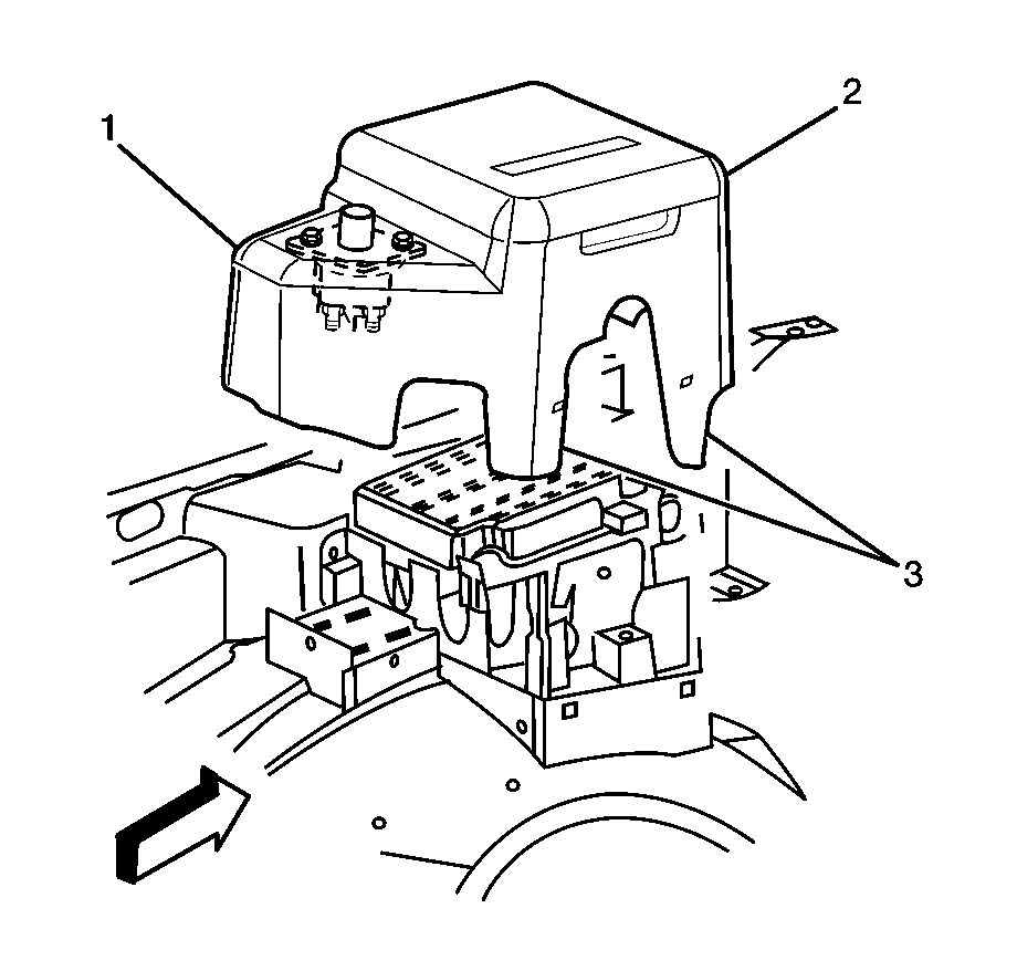
- Remove the electrical center cover assembly (1) by lifting the cover outwards to clear the tabs (3).
- Remove the switch mounting nuts and bolts.
- Remove the nuts holding the 24V and 12V cables to the switch and remove the cables.
Caution: Refer to Battery Disconnect Caution in the Preface section.
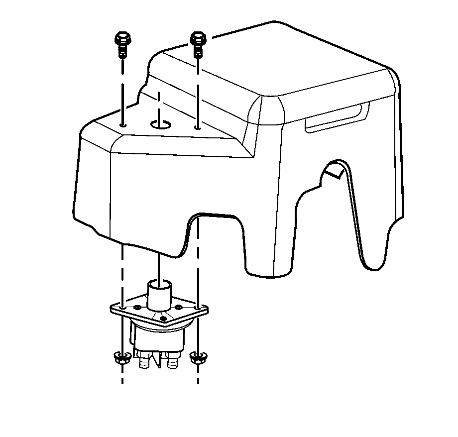
Note location of cables removed for assembly.
Installation Procedure
- Install the 24V and 12V cables to the switch and install the cable mounting nuts.
- Install the switch to the underhood electrical center cover.
- Set the electrical center cover assembly in its resting position until the tabs (3) lock into place.
- Install the fender upper brace and the disconnect switch key.
- Connect the battery cables. Refer to Battery Cable Disconnect and Connection .
Notice: Refer to Fastener Notice in the Preface section.
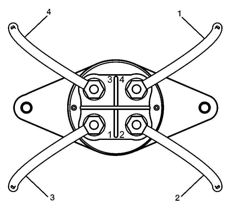
Tighten
Tighten the cable mounting nuts to 9 N·m (80 lb in).
| • | Red cable from 24V battery positive (1) to terminal 4. |
| • | Red/black cable (4) from 24V generator to terminal 3. |
| • | Red cable (3) from UBEC to terminal 1. |
| • | Red cable (2) from 24V battery negative to terminal 2. |

Tighten
Tighten the switch mounting nuts to 9 N·m (80 lb in).

Vehicle Load Disconnect Switch Replacement Ambulance
Removal Procedure
- Disconnect the battery cables. Refer to Battery Cable Disconnect and Connection .
- Remove the disconnect switch key (1) from the switch (2).
- Remove the switch mounting nuts and bolts (1).
- Remove the cable cover mounting screws (2).
- Remove the switch cable cover (3).
- Remove the nuts holding the 24V and 12V cables to the switch and remove the cables.
Caution: Refer to Battery Disconnect Caution in the Preface section.
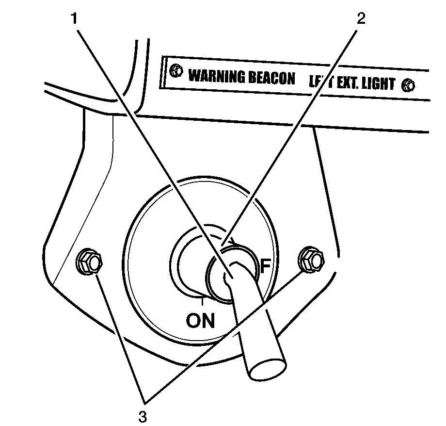
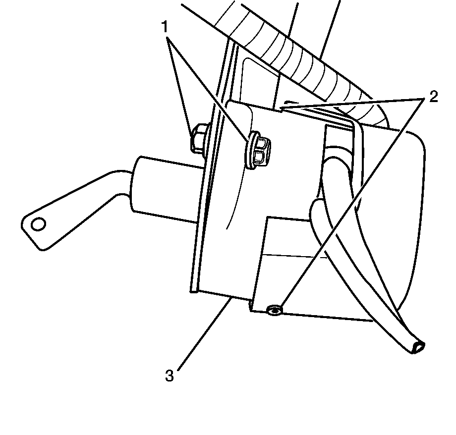
Note location of cables removed for assembly.
Installation Procedure
- Install the 24V and 12V cables to the switch and install the cable mounting nuts.
- Install the switch cable cover (3).
- Install the switch cable cover mounting screws (2).
- Install the switch to the mounting bracket and install the mounting nuts and bolts (1).
- Install the switch key (1) to the switch (2).
- Connect the battery cables. Refer to Battery Cable Disconnect and Connection .
Notice: Refer to Fastener Notice in the Preface section.

Tighten
Tighten the cable mounting nuts to 9 N·m (80 lb in).
| • | Red cable from 24V battery positive (1) to terminal 4. |
| • | Red/black cable (4) from 24V generator to terminal 3. |
| • | Red cable (3) from UBEC to terminal 1. |
| • | Red cable (2) from 24V battery negative to terminal 2. |

Tighten
Tighten the switch cable cover mounting screws to 1.6 N·m (14 lb in).
Tighten
Tighten the switch mounting nuts to 9 N·m (80 lb in).

