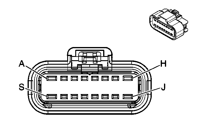
|
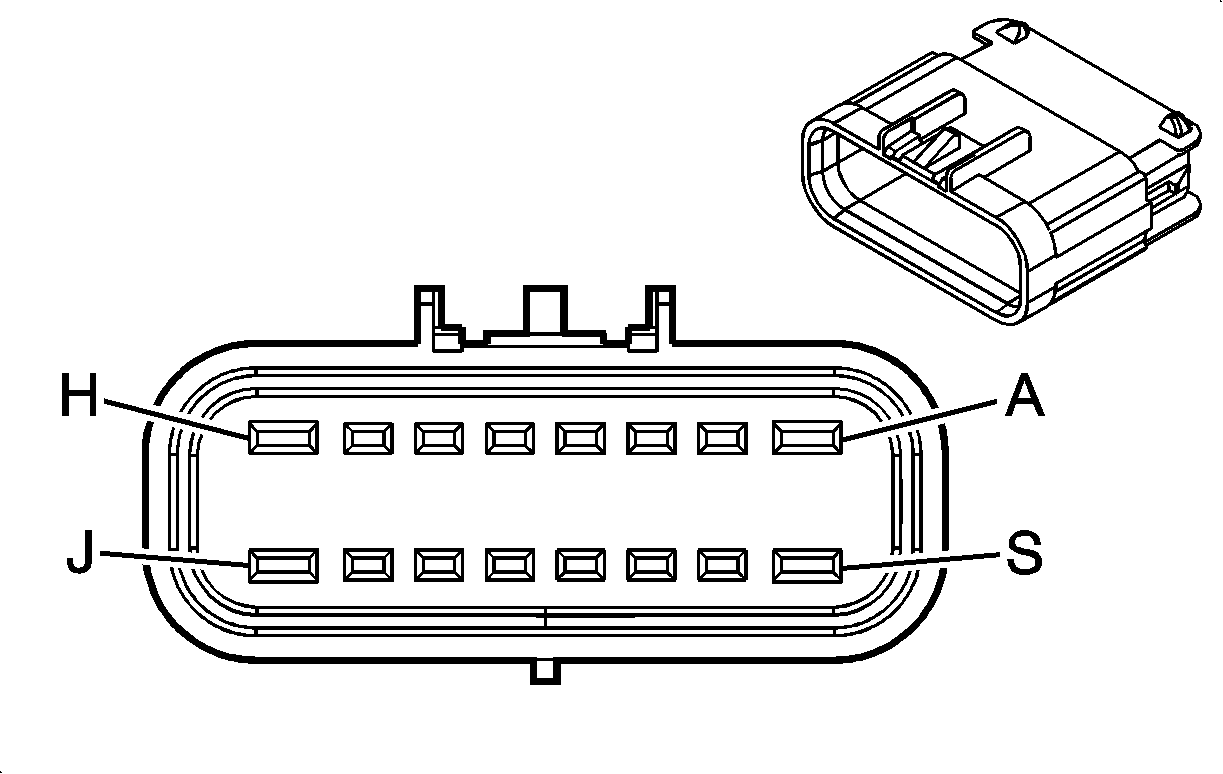
| ||||||||||||||
|---|---|---|---|---|---|---|---|---|---|---|---|---|---|---|---|
Connector Part Information |
| Connector Part Information |
| ||||||||||||
Pin | Wire Color | Circuit No. | Function | Pin | Wire Color | Circuit No. | Function | ||||||||
A | D-BU | 84 | Cruise Control Set/Coast Switch Signal (KUP) | A | D-BU | 84 | Cruise Control Set/Coast Switch Signal (KUP) | ||||||||
L-BU/BK | 396 | Cruise Control Engaged Signal (w/o KUP) | L-BU/BK | 396 | Cruise Control Engaged Signal (w/o KUP) | ||||||||||
B | GY | 48 | CPP Switch Signal (ML6, MG5) | B | GY | 48 | CPP Switch Signal (ML6, MG5) | ||||||||
C | BN | 241 | Ignition 3 Voltage (TP2) | C | BN | 241 | Ignition 3 Voltage (TP2) | ||||||||
D | D-GN/WH | 817 | Vehicle Speed Signal | D | D-GN/WH | 817 | Vehicle Speed Signal | ||||||||
E | D-BU | 507 | Wait to Start Indicator Control (Diesel) | E | D-BU | 507 | Wait to Start Indicator Control (Diesel) | ||||||||
F | OG/BK | 6752 | Class 2 Serial Data (10 Series except HP2) | F | OG/BK | 6752 | Class 2 Serial Data (10 Series except HP2) | ||||||||
G | BN/WH | 419 | MIL Control | G | BN/WH | 419 | MIL Control | ||||||||
H | D-GN | 1049 | PCM Class 2 Serial Data | H | D-GN | 1049 | PCM Class 2 Serial Data | ||||||||
J | BK/WH | 5668 | Engine ON Signal (JC4) | J | D-BU | 5668 | Engine ON Signal (JC4) | ||||||||
K | WH | 121 | Engine Speed Signal | K | WH | 121 | Engine Speed Signal | ||||||||
L | GY | 397 | Cruise Control ON Switch Signal (K34) | L | GY | 397 | Cruise Control ON Switch Signal (K34) | ||||||||
M | -- | -- | Not Used | M | -- | -- | Not Used | ||||||||
N | BN | 241 | Ignition 3 Voltage (NP1, NP2, and NP8) | N | BN | 241 | Ignition 3 Voltage (NP1, NP2, and NP8) | ||||||||
P | D-BU | 204 | A/C Low Pressure Sensor Signal (CJ2/CJ3) | P | D-BU | 204 | A/C Low Pressure Sensor Signal (CJ2/CJ3) | ||||||||
R | YE | 2470 | Class 2 Serial Data (M74) | R | YE | 2470 | Class 2 Serial Data (M74) | ||||||||
S | GY/BK | 87 | Cruise Control Resume/Accel Switch Signal | S | GY/BK | 87 | Cruise Control Resume/Accel Switch Signal | ||||||||
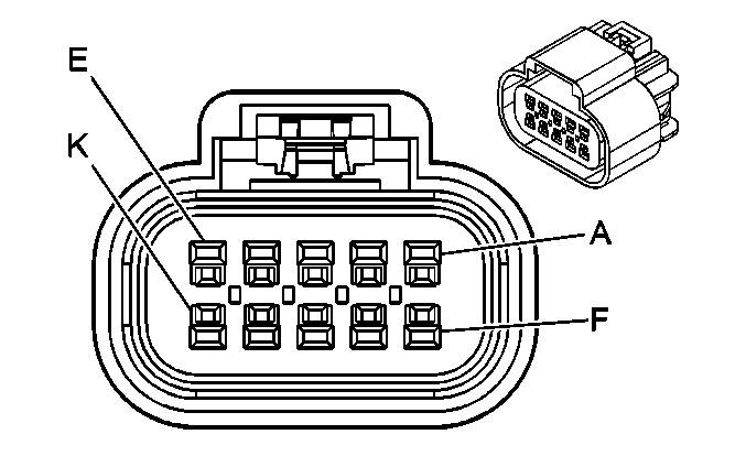
|
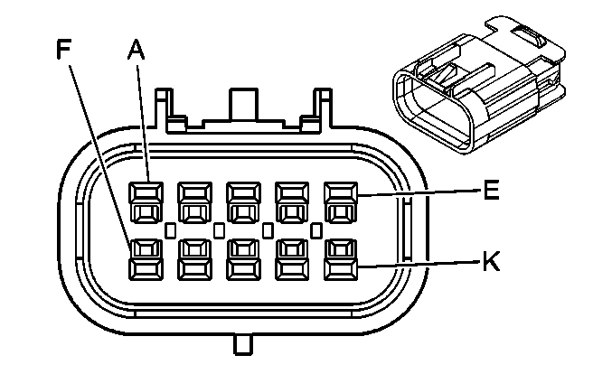
| ||||||||||||||
|---|---|---|---|---|---|---|---|---|---|---|---|---|---|---|---|
Connector Part Information |
| Connector Part Information |
| ||||||||||||
Pin | Wire Color | Circuit No. | Function | Pin | Wire Color | Circuit No. | Function | ||||||||
A | D-GN | 1619 | Trailer Right Rear Turn/Stop Lamp Supply Voltage | A | D-GN | 1619 | Trailer Right Rear Turn/Stop Lamp Supply Voltage | ||||||||
B | L-GN | 24 | Backup Lamp Supply Voltage | B | L-GN | 24 | Backup Lamp Supply Voltage | ||||||||
C | L-BU | 1122 | ABS/TCS Class 2 Serial Data | C | L-BU | 1122 | ABS/TCS Class 2 Serial Data | ||||||||
D | BN | 441 | Ignition 3 Voltage | D | BN | 441 | Ignition 3 Voltage | ||||||||
E | PK | 139 | Ignition 1 Voltage | E | PK | 139 | Ignition 1 Voltage (Except NQZ) | ||||||||
F | TN/WH | 1384 | Selective Ride Control Switch Signal (ZX3) | F | TN/WH | 1384 | Selective Ride Control Switch Signal (ZX3) | ||||||||
G | -- | -- | Not Used | G | -- | -- | Not Used | ||||||||
H | YE | 1618 | Trailer Left Rear Turn/Stop Lamp Supply Voltage | H | YE | 1618 | Trailer Left Rear Turn/Stop Lamp Supply Voltage | ||||||||
J | L-BU | 1620 | CHMSL Supply Voltage | J | L-BU | 1620 | CHMSL Supply Voltage | ||||||||
K | -- | -- | Not Used | K | -- | -- | Not Used | ||||||||
|
| ||||||||||||||
|---|---|---|---|---|---|---|---|---|---|---|---|---|---|---|---|
Connector Part Information |
| Connector Part Information |
| ||||||||||||
Pin | Wire Color | Circuit No. | Function | Pin | Wire Color | Circuit No. | Function | ||||||||
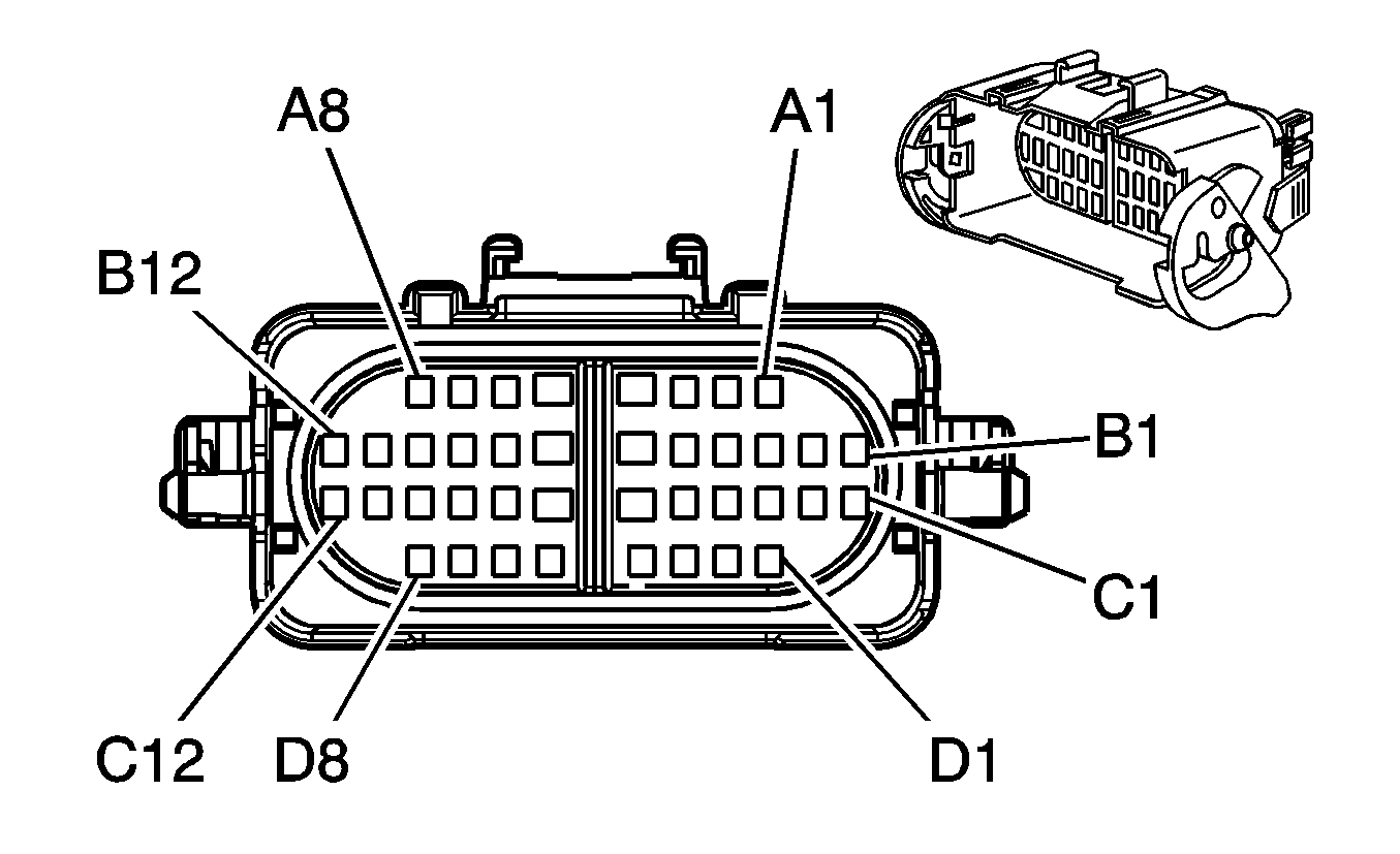
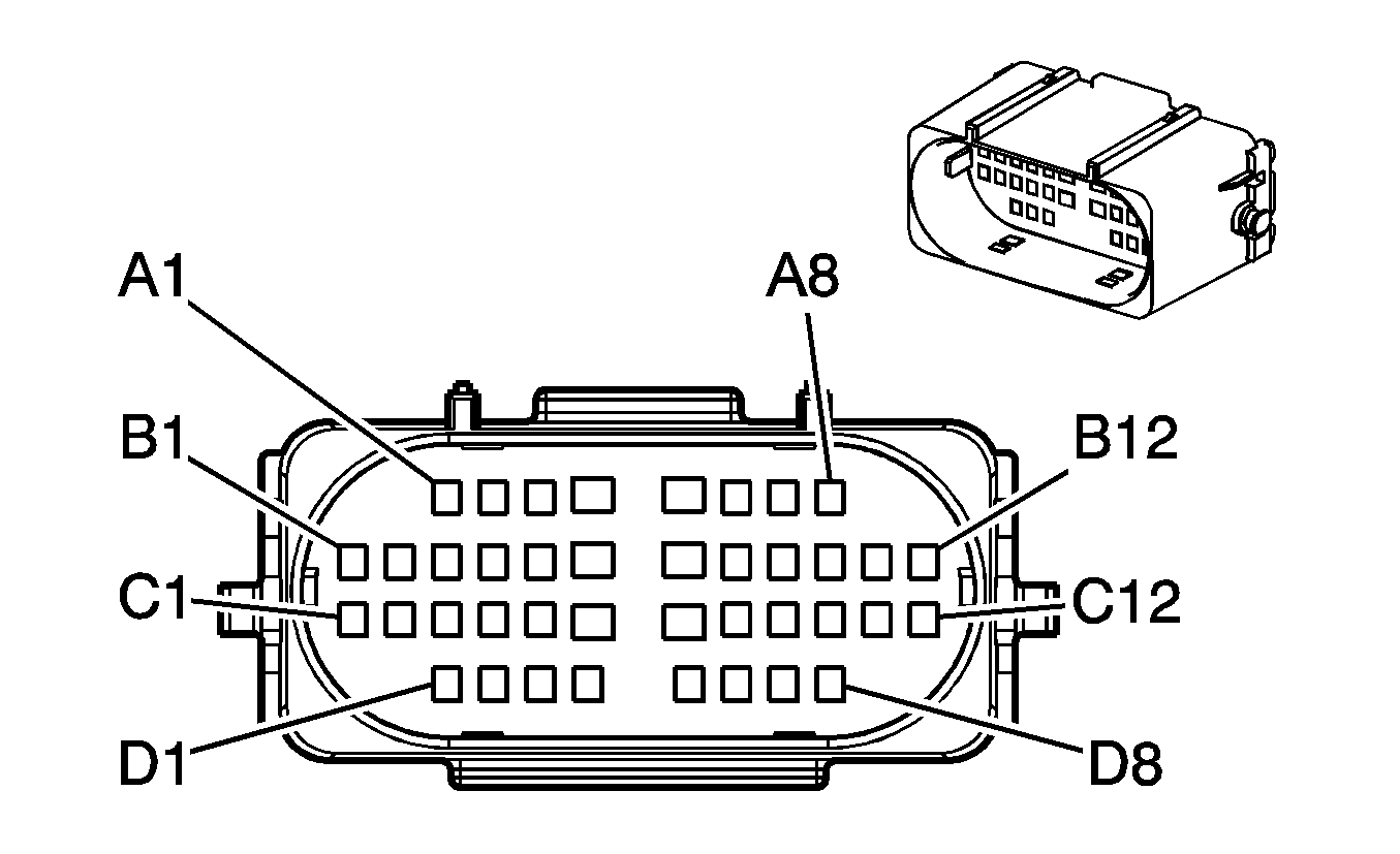
A1 | D-BU | 2544 | Rear Wheel Steer Mode Select Switch 5-Volt Reference | A1 | D-BU | 2544 | Rear Wheel Steer Mode Select Switch 5-Volt Reference | ||||||||
A2 | -- | -- | Not Used | A2 | -- | -- | Not Used | ||||||||
A3 | OG | 2538 | 4 Wheel Steer Trailer Mode Indicator Supply Voltage | A3 | OG | 2538 | 4 Wheel Steer Trailer Mode Indicator Supply Voltage | ||||||||
A4 | L-BU | 2568 | 2 Wheel Steer Mode Indicator Supply Voltage | A4 | L-BU | 2568 | 2 Wheel Steer Mode Indicator Supply Voltage | ||||||||
A5 | TN | 2569 | 4 Wheel Steer Mode Indicator Supply Voltage | A5 | TN | 2569 | 4 Wheel Steer Mode Indicator Supply Voltage | ||||||||
A6 | D-GN/WH | 817 | Vehicle Speed Signal | A6 | D-GN/WH | 817 | Vehicle Speed Signal | ||||||||
A7 | GY | 2567 | Class 2 Serial Data | A7 | GY | 2567 | Class 2 Serial Data | ||||||||
A8 | D-GN/WH | 2891 | Rear Wheel Steering Mode Select Switch Signal | A8 | D-GN/WH | 2891 | Rear Wheel Steering Mode Select Switch Signal | ||||||||
B1 | -- | -- | Not Used | B1 | -- | -- | Not Used | ||||||||
B2 | L-GN | 1763 | Steering Wheel Position Signal A | B2 | L-GN | 1763 | Steering Wheel Position Signal A | ||||||||
B3 | L-BU | 1764 | Steering Wheel Position Signal B | B3 | L-BU | 1764 | Steering Wheel Position Signal B | ||||||||
B4 | WH | 1765 | Steering Wheel Position Marker Pulse Signal | B4 | WH | 1765 | Steering Wheel Position Marker Pulse Signal | ||||||||
B5-B7 | -- | -- | Not Used | B5-B7 | -- | -- | Not Used | ||||||||
B8 | BN | 541 | Ignition 3 Voltage | B8 | BN | 541 | Ignition 3 Voltage | ||||||||
B9 | -- | -- | Not Used | B9 | -- | -- | Not Used | ||||||||
C1-C2 | -- | -- | Not Used | C1-C2 | -- | -- | Not Used | ||||||||
C3 | 1619 | D-GN | Trailer Right Rear Turn/Stop Lamps Supply Voltage | C3 | 1619 | D-GN | Trailer Right Rear Turn/Stop Lamps Supply Voltage | ||||||||
C4 | L-GN | 24 | Backup Lamp Supply Voltage | C4 | L-GN | 24 | Backup Lamp Supply Voltage | ||||||||
C5 | L-BU | 1122 | Class 2 Serial Data | C5 | L-BU | 1122 | Class 2 Serial Data | ||||||||
C6 | BN | 441 | Ignition 3 Voltage | C6 | BN | 441 | Ignition 3 Voltage | ||||||||
C7 | TN/WH | 1384 | Selective Ride Control Switch Signal (ZX3) | C7 | TN/WH | 1384 | Selective Ride Control Switch Signal (ZX3) | ||||||||
C8 | -- | -- | Not Used | C8 | -- | -- | Not Used | ||||||||
C9 | YE | 1618 | Trailer Left Rear Turn/Stop Lamp Supply Voltage | C9 | YE | 1618 | Trailer Left Rear Turn/Stop Lamp Supply Voltage | ||||||||
C10 | L-BU | 1620 | CHMSL Supply Voltage | C10 | L-BU | 1620 | CHMSL Supply Voltage | ||||||||
C11-C12 | -- | -- | Not Used | C11-C12 | -- | -- | Not Used | ||||||||
D1 | PK | 139 | Ignition 1 Voltage | D1 | PK | 139 | Ignition 1 Voltage (Except NQZ) | ||||||||
D2-D3 | -- | -- | Not Used | D1-D3 | -- | -- | Not Used | ||||||||
D4-D5 | -- | -- | Unavailable | D4-D5 | -- | -- | Unavailable | ||||||||
D6-D8 | -- | -- | Not Used | D6-D8 | -- | -- | Not Used | ||||||||
|
| ||||||||||||||
|---|---|---|---|---|---|---|---|---|---|---|---|---|---|---|---|
Connector Part Information |
| Connector Part Information |
| ||||||||||||
Pin | Wire Color | Circuit No. | Function | Pin | Wire Color | Circuit No. | Function | ||||||||
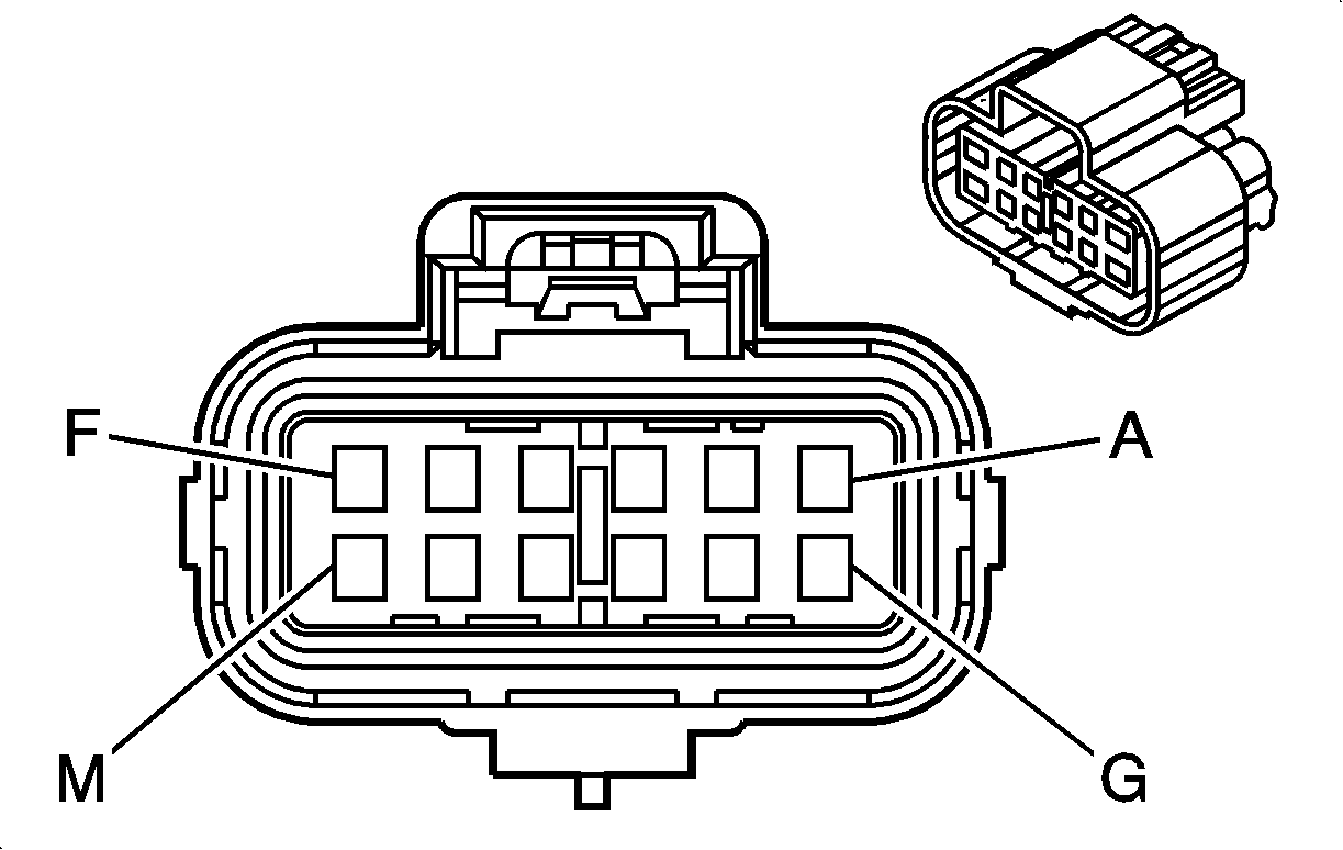
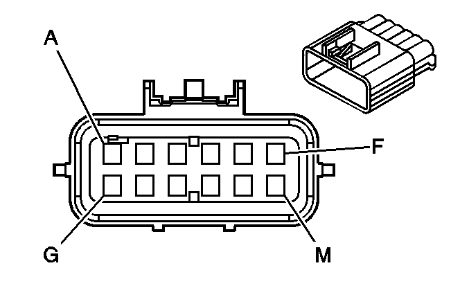
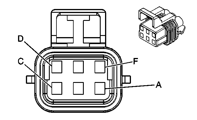
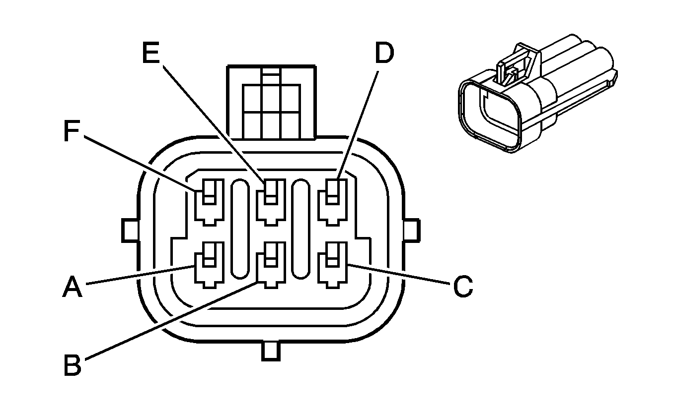
A | GY | 349 | Discriminating Sensor - Left - Signal | A | GY | 349 | Discriminating Sensor - Left - Signal (AL0) | ||||||||
B | YE | 354 | Discriminating Sensor - Signal | B | YE | 354 | Discriminating Sensor - Signal (AL0) | ||||||||
C | YE | 1834 | Forward Discriminating Sensor Signal | C | YE | 1834 | Forward Discriminating Sensor Signal | ||||||||
D | D-GN | 1409 | Discriminating Sensor - Right - Signal | D | D-GN | 1409 | Discriminating Sensor - Right - Signal | ||||||||
E | -- | -- | Not Used | E | -- | -- | Not Used | ||||||||
F | BK/WH | 174 | Low Washer Fluid Indicator Signal | F | BK/WH | 174 | Low Washer Fluid Indicator Signal | ||||||||
G | D-GN/WH | 636 | Ambient Air Temperature Sensor Signal (DF5) | G | D-GN/WH | 636 | Ambient Air Temperature Sensor Signal (DF5) | ||||||||
H | BK/WH | 1704 | Low Reference (DF5) | H | BK/WH | 1704 | Low Reference (DF5) | ||||||||
J | L-GN/BK | 735 | Ambient Air Temperature Sensor Signal (CJ2) | J | L-GN/BK | 735 | Ambient Air Temperature Sensor Signal (CJ2) | ||||||||
K | BN | 718 | Low Reference (CJ2) | K | BN | 718 | Low Reference (CJ2) | ||||||||
L-M | -- | -- | Not Used | L-M | -- | -- | Not Used | ||||||||
|
| ||||||||||||||
|---|---|---|---|---|---|---|---|---|---|---|---|---|---|---|---|
Connector Part Information |
| Connector Part Information |
| ||||||||||||
Pin | Wire Color | Circuit No. | Function | Pin | Wire Color | Circuit No. | Function | ||||||||
A | GY | 349 | Discriminating Sensor - Left - Signal | A | GY | 349 | Discriminating Sensor - Left - Signal | ||||||||
B | YE | 354 | Discriminating Sensor - Signal | B | YE | 354 | Discriminating Sensor - Signal | ||||||||
C | YE | 1834 | Forward Discriminating Sensor Signal | C | YE | 1834 | Forward Discriminating Sensor Signal | ||||||||
D | D-GN | 1409 | Discriminating Sensor - Right - Signal | D | D-GN | 1409 | Discriminating Sensor - Right - Signal | ||||||||
E | -- | -- | Not Used | E | -- | -- | Not Used | ||||||||
F | BK/WH | 174 | Low Washer Fluid Indicator Signal | F | BK/WH | 174 | Low Washer Fluid Indicator Signal | ||||||||
|
| ||||||||||||||
|---|---|---|---|---|---|---|---|---|---|---|---|---|---|---|---|
Connector Part Information |
| Connector Part Information |
| ||||||||||||
Pin | Wire Color | Circuit No. | Function | Pin | Wire Color | Circuit No. | Function | ||||||||
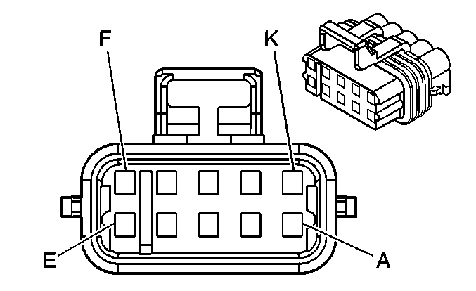
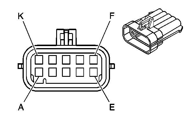
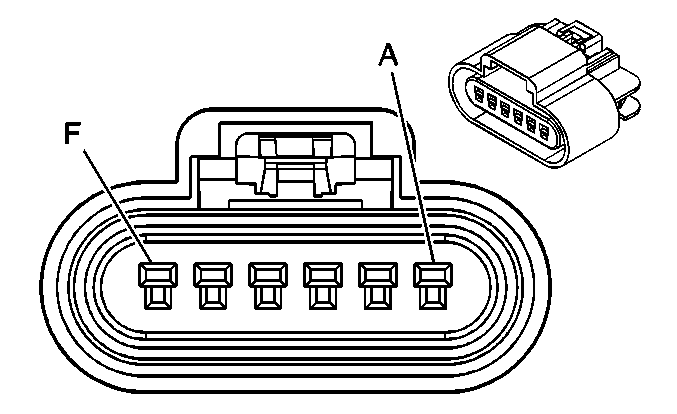
A | GY | 1273 | Low Reference | A | GY | 1273 | Low Reference | ||||||||
B | PU | 1272 | Low Reference | B | PU | 1272 | Low Reference | ||||||||
C | L-BU | 1162 | APP Sensor 2 Signal | C | L-BU | 1162 | APP Sensor 2 Signal | ||||||||
D | TN | 1274 | 5-Volt Reference | D | TN | 1274 | 5-Volt Reference | ||||||||
E | YE/BK | 1275 | 5-Volt Reference | E | YE/BK | 1275 | 5-Volt Reference | ||||||||
F | D-BU | 1161 | APP Sensor 1 Signal | F | D-BU | 1161 | APP Sensor 1 Signal | ||||||||
G | WH/BK | 1164 | 5-Volt Reference | G | WH/BK | 1164 | 5-Volt Reference | ||||||||
H | -- | -- | Not Used | H | -- | -- | Not Used | ||||||||
J | BN | 1271 | Low Reference | J | BN | 1271 | Low Reference | ||||||||
K | D-GN | 1163 | APP Sensor 3 Signal | K | D-GN | 1163 | APP Sensor 3 Signal | ||||||||
|
| ||||||||||||||
|---|---|---|---|---|---|---|---|---|---|---|---|---|---|---|---|
Connector Part Information |
| Connector Part Information |
| ||||||||||||
Pin | Wire Color | Circuit No. | Function | Pin | Wire Color | Circuit No. | Function | ||||||||
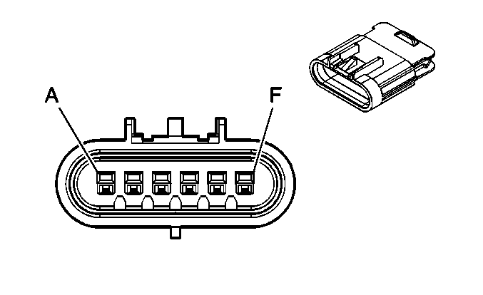
A | YE | 2522 | PTO Engage Signal | A | YE | 2522 | PTO Engage Signal | ||||||||
B | -- | -- | Not Used | B | -- | -- | Not Used | ||||||||
C | L-GN | 488 | PTO On Switch-Signal | C | L-GN | 488 | PTO On Switch-Signal | ||||||||
D | -- | -- | Not Used | D | -- | -- | Not Used | ||||||||
E | D-BU | 84 | Cruise Control Set/Coast Switch Signal | E | D-BU | 84 | Cruise Control Set/Coast Switch Signal | ||||||||
F | -- | -- | Not Used | F | -- | -- | Not Used | ||||||||

|

| ||||||||||||||
|---|---|---|---|---|---|---|---|---|---|---|---|---|---|---|---|
Connector Part Information |
| Connector Part Information |
| ||||||||||||
Pin | Wire Color | Circuit No. | Function | Pin | Wire Color | Circuit No. | Function | ||||||||
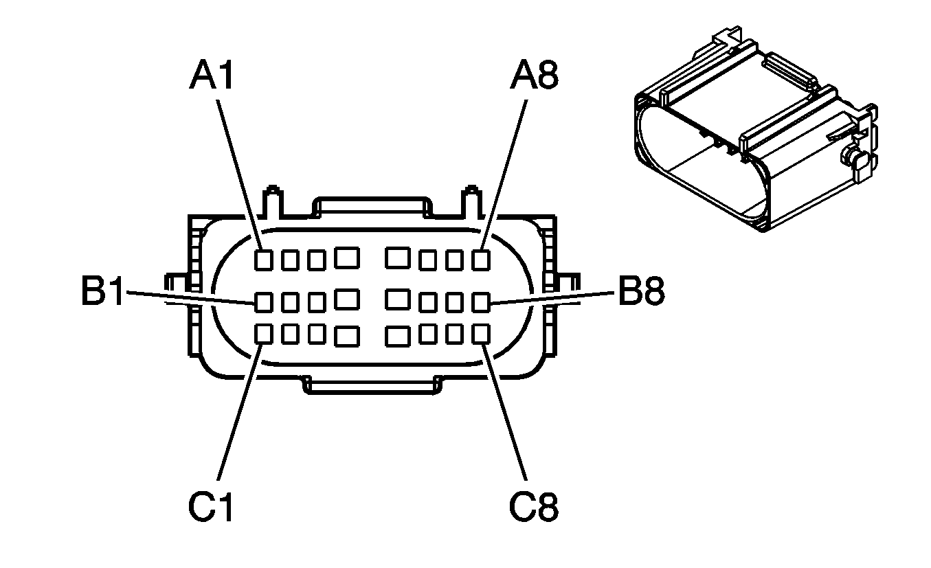
A1 | PK | 239 | Ignition 1 Voltage | A1 | PK | 239 | Ignition 1 Voltage | ||||||||
A2 | YE | 505 | Glow Plug Relay Control | A2 | YE | 505 | Glow Plug Relay Control | ||||||||
A3 | -- | -- | Not Used | A3 | -- | -- | Not Used | ||||||||
A4 | PK | 339 | Ignition 1 Voltage | A4 | PK | 339 | Ignition 1 Voltage | ||||||||
A5 | PK | 339 | Ignition 1 Voltage | A5 | PK | 339 | Ignition 1 Voltage | ||||||||
A6 | BN | 1174 | Oil Level Switch Signal | A6 | BN | 1174 | Oil Level Switch Signal | ||||||||
A7 | YE | 410 | ECT Sensor Signal | A7 | YE | 410 | ECT Sensor Signal | ||||||||
A8 | GY | 720 | Low Reference | A8 | GY | 720 | Low Reference | ||||||||
B1 | L-GN/BK | 1745 | Fuel Injector 2 Control | B1 | L-GN/BK | 1745 | Fuel Injector 2 Control | ||||||||
B2 | RD/BK | 877 | Fuel Injector 7 Control | B2 | RD/BK | 877 | Fuel Injector 7 Control | ||||||||
B3 | RD | 631 | 5-Volt Reference | B3 | RD | 631 | 5-Volt Reference | ||||||||
B4 | BN/WH | 633 | CMP Sensor Signal | B4 | BN/WH | 633 | CMP Sensor Signal | ||||||||
B5 | PK/BK | 632 | Low Reference | B5 | PK/BK | 632 | Low Reference | ||||||||
B6-B7 | -- | -- | Not Used | B6-B7 | -- | -- | Not Used | ||||||||
B8 | YE/BK | 1868 | Low Reference | B8 | YE/BK | 1868 | Low Reference | ||||||||
B9 | D-BU/WH | 1869 | CKP Sensor Signal | B9 | D-BU/WH | 1869 | CKP Sensor Signal | ||||||||
B10 | L-GN | 1867 | 12-Volt Reference | B10 | L-GN | 1867 | 12-Volt Reference | ||||||||
B11 | YE /BK | 846 | Fuel Injector 6 Control | B11 | YE /BK | 846 | Fuel Injector 6 Control | ||||||||
B12 | PK/BK | 1746 | Fuel Injector 3 Control | B12 | PK/BK | 1746 | Fuel Injector 3 Control | ||||||||
C1 | BK | 1744 | Fuel Injector 1 Control | C1 | BK | 1744 | Fuel Injector 1 Control | ||||||||
C2 | BK/WH | 845 | Fuel Injector 5 Control | C2 | BK/WH | 845 | Fuel Injector 5 Control | ||||||||
C3 | TN | 2917 | 5-Volt Reference | C3 | TN | 2917 | 5-Volt Reference | ||||||||
C4 | OG/BK | 2919 | Low Reference | C4 | OG/BK | 2919 | Low Reference | ||||||||
C5 | YE | 2918 | FRP Sensor Signal | C5 | YE | 2918 | FRP Sensor Signal | ||||||||
C6 | PK | 239 | Ignition 1 Voltage | C6 | PK | 239 | Ignition 1 Voltage | ||||||||
C7 | -- | -- | Not Used | C7 | -- | -- | Not Used | ||||||||
C8 | L-BU | 2832 | Engine Speed Signal | C8 | L-BU | 2832 | Engine Speed Signal | ||||||||
C9 | YE | 2834 | Fuel Pressure Regulator Solenoid Control | C9 | YE | 2834 | Fuel Pressure Regulator Solenoid Control | ||||||||
C10 | PU/WH | 2530 | Fuel Pressure Regulator Solenoid Supply Voltage | C10 | PU/WH | 2530 | Fuel Pressure Regulator Solenoid Supply Voltage | ||||||||
C11 | D-BU/WH | 878 | Fuel Injector 8 Control | C11 | D-BU/WH | 878 | Fuel Injector 8 Control | ||||||||
C12 | L-BU/BKBK | 844 | Fuel Injector 4 Control | C12 | L-BU/BK | 844 | Fuel Injector 4 Control | ||||||||
D1 | YE | 1578 | Fuel Temperature Signal | D1 | YE | 1578 | Fuel Temperature Signal | ||||||||
D2 | BN | 718 | Low Reference | D2 | BN | 718 | Low Reference | ||||||||
D3 | YE/BK | 508 | Water In Fuel Indicator Control | D3 | YE/BK | 508 | Water In Fuel Indicator Control | ||||||||
D4-D5 | -- | -- | Unavailable | D4-D5 | -- | -- | Unavailable | ||||||||
D6 | TN/WH | 332 | Oil Pressure Sensor Signal | D6 | TN/WH | 332 | Oil Pressure Sensor Signal | ||||||||
D7 | BK | 2755 | Low Reference | D7 | BK | 2755 | Low Reference | ||||||||
D8 | GY | 2705 | 5-Volt Reference | D8 | GY | 2705 | 5-Volt Reference | ||||||||
|
| ||||||||||||||
|---|---|---|---|---|---|---|---|---|---|---|---|---|---|---|---|
Connector Part Information |
| Connector Part Information |
| ||||||||||||
Pin | Wire Color | Circuit No. | Function | Pin | Wire Color | Circuit No. | Function | ||||||||
A1-A2 | -- | -- | Not Used | A1-A2 | -- | -- | Not Used | ||||||||
A3 | D-BU/WH | 5763 | EGR Valve Position Signal | A3 | BN/WH | 5763 | EGR Valve Position Signal | ||||||||
A4-A5 | -- | -- | Not Used | A4-A5 | -- | -- | Not Used | ||||||||
A6 | WH/BK | 2932 | 5-Volt Reference | A6 | WH/BK | 2932 | 5-Volt Reference | ||||||||
A7 | OG/BK | 1057 | Low Reference | A7 | OG/BK | 1057 | Low Reference | ||||||||
A8 | GY/BK | 433 | BARO Sensor Signal | A8 | GY/BK | 433 | BARO Sensor Signal | ||||||||
B1 | D-GN | 2362 | SAE J1939 Serial Data Bus- | B1 | D-GN | 2362 | SAE J1939 Serial Data Bus- | ||||||||
B2 | -- | -- | Not Used | B2 | -- | -- | Not Used | ||||||||
B3 | YE/BK | 2754 | Low Reference | B3 | BK | 2754 | Low Reference | ||||||||
B4 | D-BU | 5930 | Turbocharger Vane Position Control Solenoid Valve High control | B4 | D-BU | 5930 | Turbocharger Vane Position Control Solenoid Valve High control | ||||||||
B5 | WH | 5931 | Low Reference | B5 | WH | 5931 | Low Reference | ||||||||
B6 | OG/BK | 5929 | 5-Volt Reference | B6 | OG/BK | 5929 | 5-Volt Reference | ||||||||
B7 | TN | 5928 | Low Reference | B7 | TN | 5928 | Low Reference | ||||||||
B8 | YE | 5947 | Turbocharger Vane Position Sensor Signal | B8 | YE | 5947 | Turbocharger Vane Position Sensor Signal | ||||||||
C1 | YE | 2361 | SAE J1939 Serial Data Bus+ | C1 | YE | 2361 | SAE J1939 Serial Data Bus+ | ||||||||
C2 | -- | -- | Not Used | C2 | GY/BK | 5765 | Fuel Filter Pressure Switch Signal | ||||||||
C3 | PU | 2703 | 5-Volt Reference | C3 | GY | 2703 | 5-Volt Reference | ||||||||
C4 | PK | 5764 | EGR Motor High Control | C4 | OG/BK | 5764 | EGR Motor High Control | ||||||||
C5 | WH | 5746 | EGR Motor Low Control | C5 | L-GN/BK | 5746 | EGR Motor Low Control | ||||||||
C6 | GY | 597 | 5-Volt Reference | C6 | GY | 597 | 5-Volt Reference | ||||||||
C7 | OG/BK | 469 | Low Reference | C7 | OG/BK | 469 | Low Reference | ||||||||
C8 | L-GN | 432 | Turbocharger Boost Sensor Signal | C8 | L-GN | 432 | Turbocharger Boost Sensor Signal | ||||||||
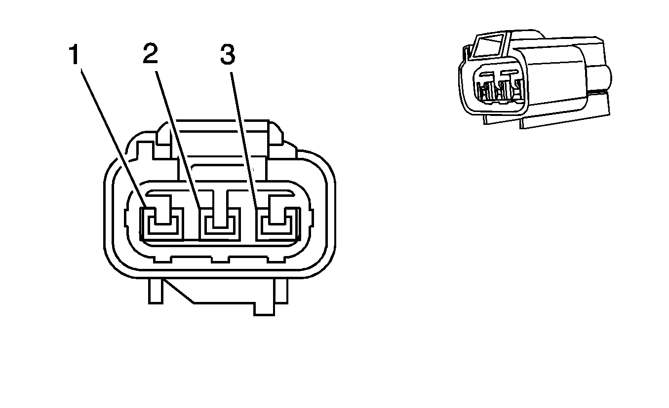
|
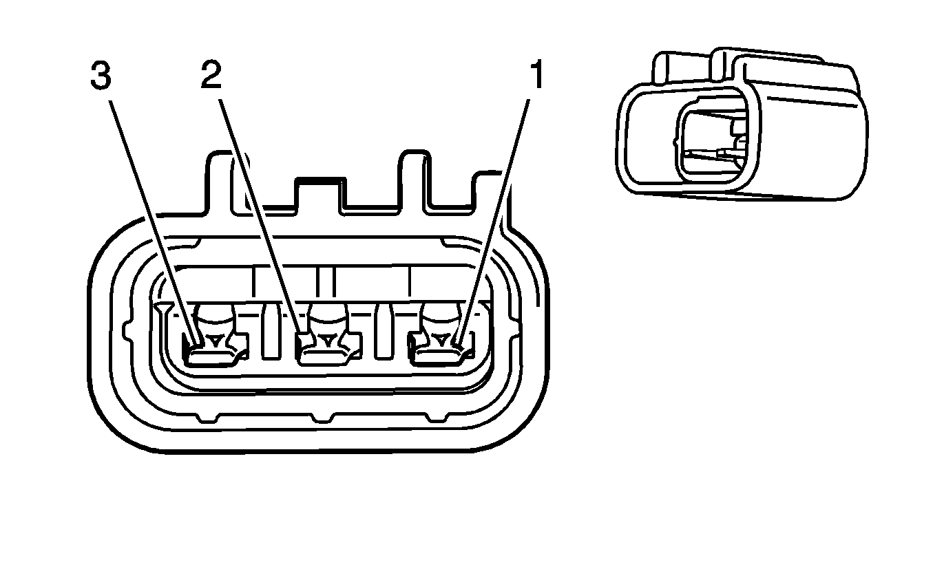
| ||||||||||||||
|---|---|---|---|---|---|---|---|---|---|---|---|---|---|---|---|
Connector Part Information |
| Connector Part Information |
| ||||||||||||
Pin | Wire Color | Circuit No. | Function | Pin | Wire Color | Circuit No. | Function | ||||||||
1 | BARE | -- | Drain Wire | 1 | BARE | -- | Drain Wire | ||||||||
2 | YE | 2834 | Fuel Pressure Regulator Solenoid | 2 | YE | 2834 | Fuel Pressure Regulator Solenoid | ||||||||
3 | PU/WH | 2530 | Fuel Pressure Regulator Solenoid Supply Voltage | 3 | PU/WH | 2530 | Fuel Pressure Regulator Solenoid Supply Voltage | ||||||||
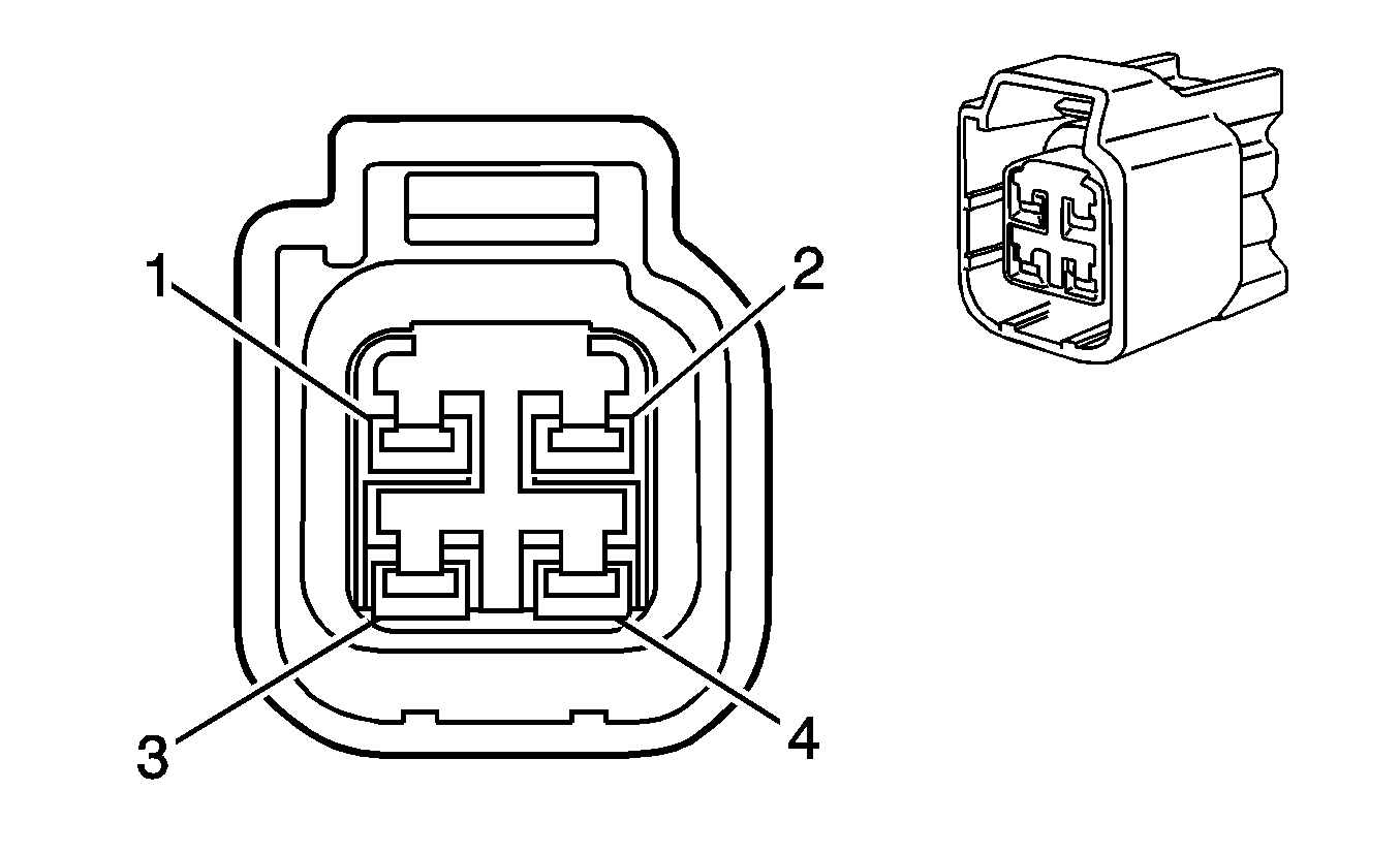
|
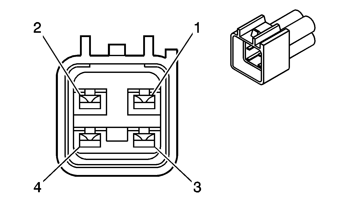
| ||||||||||||||
|---|---|---|---|---|---|---|---|---|---|---|---|---|---|---|---|
Connector Part Information |
| Connector Part Information |
| ||||||||||||
Pin | Wire Color | Circuit No. | Function | Pin | Wire Color | Circuit No. | Function | ||||||||
1 | OG/BK | 2919 | Low Reference | 1 | OG/BK | 2919 | Low Reference | ||||||||
2 | YE | 2918 | FRP Sensor Signal | 2 | YE | 2918 | FRP Sensor Signal | ||||||||
3 | -- | -- | Not Used | 3 | -- | -- | Not Used | ||||||||
4 | TN | 2917 | 5-Volt Reference | 3 | D-BU | 2917 | 5-Volt Reference | ||||||||
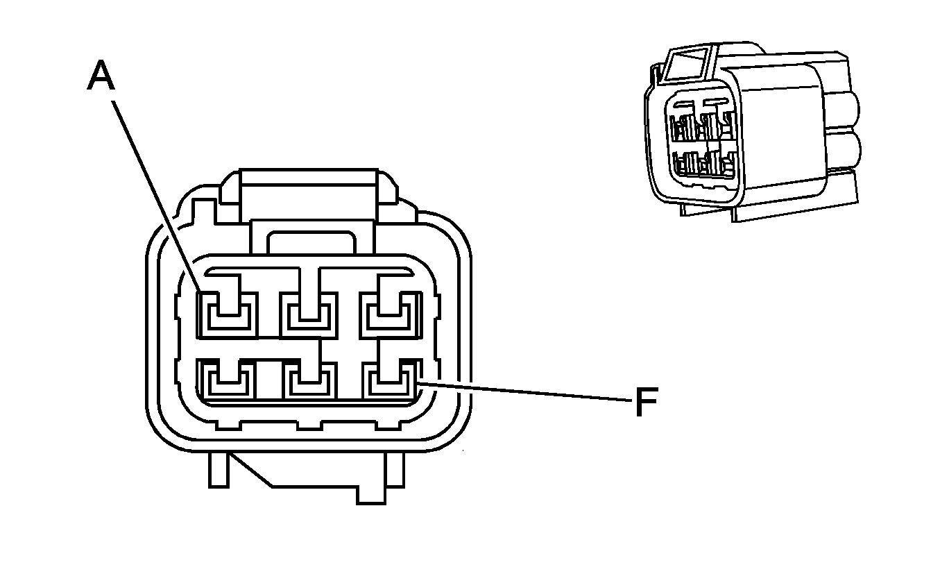
|
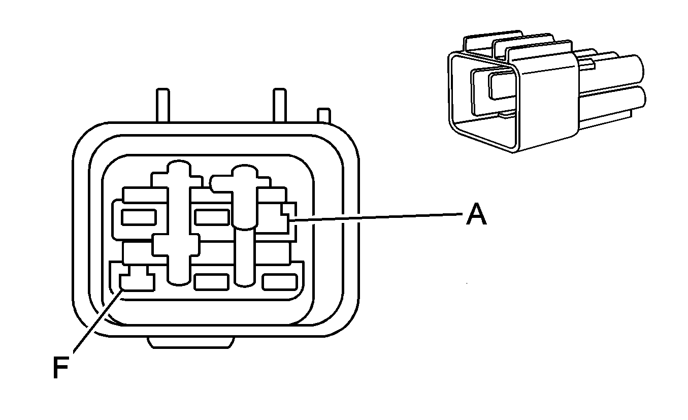
| ||||||||||||||
|---|---|---|---|---|---|---|---|---|---|---|---|---|---|---|---|
Connector Part Information |
| Connector Part Information |
| ||||||||||||
Pin | Wire Color | Circuit No. | Function | Pin | Wire Color | Circuit No. | Function | ||||||||
A | PK/YE | -- | Ground | A | PK/YE | -- | Ground | ||||||||
B | TN/WH | 332 | Oil Pressure Sensor Signal | B | TN/WH | 332 | Oil Pressure Sensor Signal | ||||||||
C | BN | 1174 | Oil Level Switch Signal | C | BN | 1174 | Oil Level Switch Signal | ||||||||
D | GY | 2705 | 5-Volt Reference | D | GY | 2705 | 5-Volt Reference | ||||||||
E | BK | 2755 | Low Reference | E | BK | 2755 | Low Reference | ||||||||
F | -- | -- | Not Used | F | -- | -- | Not Used | ||||||||
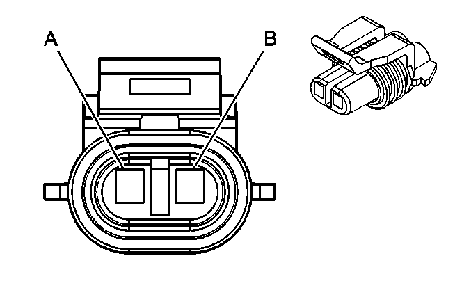
|
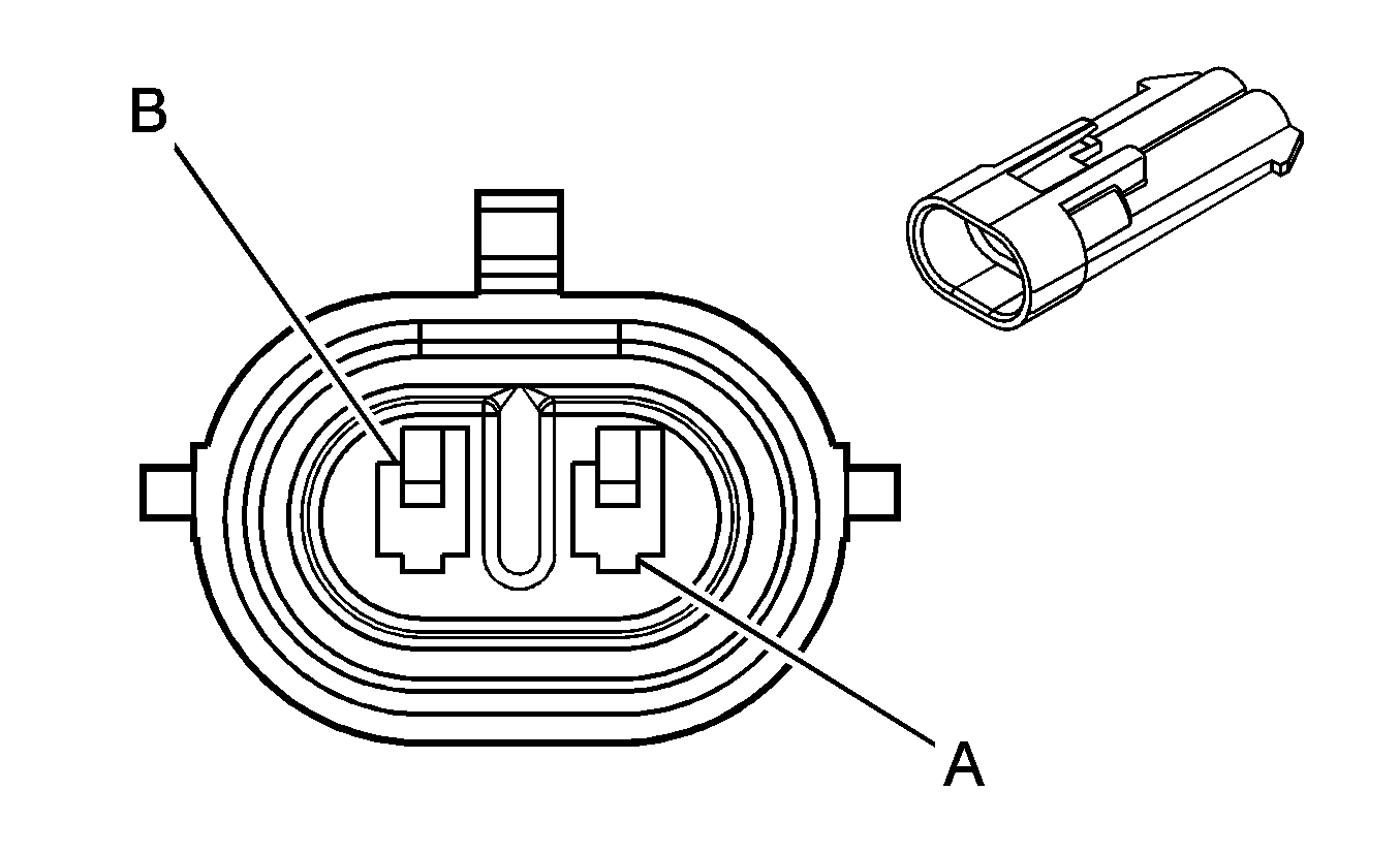
| ||||||||||||||
|---|---|---|---|---|---|---|---|---|---|---|---|---|---|---|---|
Connector Part Information |
| Connector Part Information |
| ||||||||||||
Pin | Wire Color | Circuit No. | Function | Pin | Wire Color | Circuit No. | Function | ||||||||
A | D-BU | 496 | Knock Sensor 1 Signal | A | D-BU | 496 | Knock Sensor 1 Signal | ||||||||
B | L-BU | 1876 | Knock Sensor 2 Signal | B | L-BU | 1876 | Knock Sensor 2 Signal | ||||||||

|

| ||||||||||||||
|---|---|---|---|---|---|---|---|---|---|---|---|---|---|---|---|
Connector Part Information |
| Connector Part Information |
| ||||||||||||
Pin | Wire Color | Circuit No. | Function | Pin | Wire Color | Circuit No. | Function | ||||||||
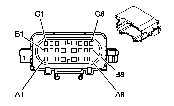
A1 | OG | 2740 | Battery Positive Voltage | A1 | OG | 2740 | Battery Positive Voltage | ||||||||
A2 | PK | 1639 | Ignition 1 Voltage | A2 | PK | 1639 | Ignition 1 Voltage | ||||||||
A3 | PU/WH | 5687 | Hybrid Control Module Class 2 Serial Data | A3 | PU/WH | 5687 | Hybrid Control Module Class 2 Serial Data | ||||||||
A4 | PK | 3 | Ignition 1 Voltage | A4 | PK | 3 | Ignition 1 Voltage | ||||||||
A5 | -- | -- | Not Used | A5 | -- | -- | Not Used | ||||||||
A6 | BN/WH | 5682 | Electric Power Take Off Switch Low Reference | A6 | BN/WH | 5682 | Electric Power Take Off Switch Low Reference | ||||||||
A7 | PK | 1939 | Ignition 1 Voltage | A7 | PK | 1939 | Ignition 1 Voltage | ||||||||
A8 | GY/BK | 5689 | Brake Pedal Position Sensor Low Reference | A8 | GY/BK | 5689 | Brake Pedal Position Sensor Low Reference | ||||||||
B1 | YE | 5066 | Brake Pedal Position Sensor Signal | B1 | YE | 5066 | Brake Pedal Position Sensor Signal | ||||||||
B2 | PU | 5681 | Electric Power Take Off Switch Signal | B2 | PU | 5681 | Electric Power Take Off Switch Signal | ||||||||
B3 | YE | 5680 | Electric Power Take Off LED Signal | B3 | YE | 5680 | Electric Power Take Off LED Signal | ||||||||
B4 | RD | 342 | Battery Positive Voltage | B4 | RD | 342 | Battery Positive Voltage | ||||||||
B5-B6 | -- | -- | Not Used | B5-B6 | -- | -- | Not Used | ||||||||
B7 | BK/WH | 1851 | Ground | B7 | BK/WH | 1851 | Ground | ||||||||
B8 | L-GN | 1763 | Steering Wheel Position Signal A | B8 | L-GN | 1763 | Steering Wheel Position Signal A | ||||||||
C1 | L-BU | 1764 | Steering Wheel Position Signal B | C1 | L-BU | 1764 | Steering Wheel Position Signal B | ||||||||
C2-C3 | -- | -- | Not Used | C2-C3 | -- | -- | Not Used | ||||||||
C4 | D-GN | 591 | Ignition 1 Voltage | C4 | D-GN | 591 | Ignition 1 Voltage | ||||||||
C5 | -- | -- | Not Used | C5 | -- | -- | Not Used | ||||||||
C6 | OG | 5688 | Brake Pedal Position Sensor 5-Volt Reference | C6 | OG | 5688 | Brake Pedal Position Sensor 5-Volt Reference | ||||||||
C7 | TN/WH | 2500 | High Speed GMLAN Serial Data Bus+ | C7 | TN/WH | 2500 | High Speed GMLAN Serial Data Bus+ | ||||||||
C8 | TN | 2501 | High Speed GMLAN Serial Data Bus- | C8 | TN | 2501 | High Speed GMLAN Serial Data Bus- | ||||||||
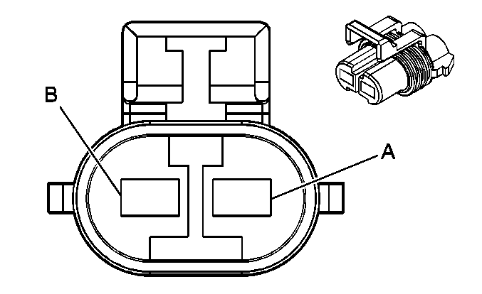
|
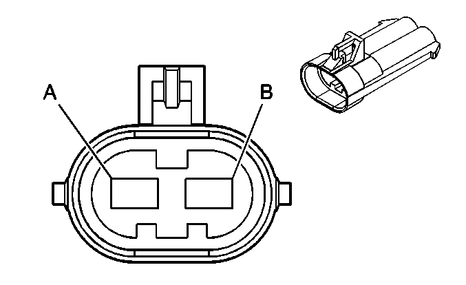
| ||||||||||||||
|---|---|---|---|---|---|---|---|---|---|---|---|---|---|---|---|
Connector Part Information |
| Connector Part Information |
| ||||||||||||
Pin | Wire Color | Circuit No. | Function | Pin | Wire Color | Circuit No. | Function | ||||||||
A | BK | 50 | Ground | A | BK | 50 | Ground | ||||||||
B | -- | -- | Unavailable | B | -- | -- | Unavailable | ||||||||
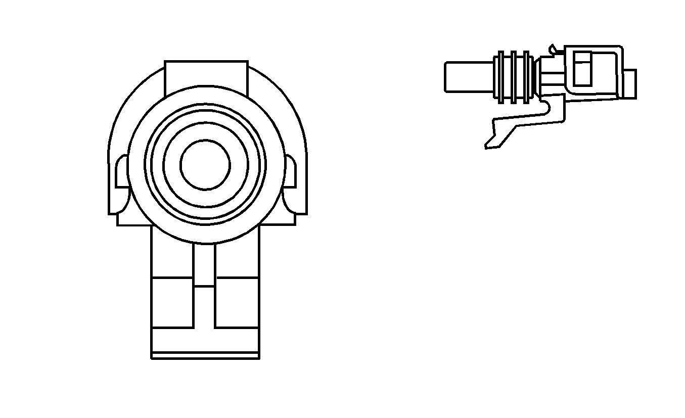
|
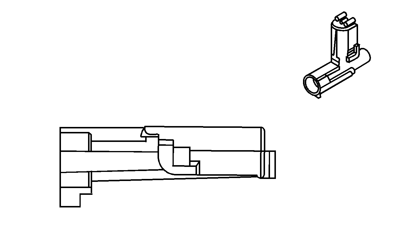
| ||||||||||||||
|---|---|---|---|---|---|---|---|---|---|---|---|---|---|---|---|
Connector Part Information |
| Connector Part Information |
| ||||||||||||
Pin | Wire Color | Circuit No. | Function | Pin | Wire Color | Circuit No. | Function | ||||||||
A | BK | 50 | Ground | A | BK | 50 | Ground | ||||||||

|

| ||||||||||||||
|---|---|---|---|---|---|---|---|---|---|---|---|---|---|---|---|
Connector Part Information |
| Connector Part Information |
| ||||||||||||
Pin | Wire Color | Circuit No. | Function | Pin | Wire Color | Circuit No. | Function | ||||||||
A | BK | 50 | Ground | A | BK | 50 | Ground | ||||||||
B | RD | 2 | Battery Positive Voltage | B | RD | 2 | Battery Positive Voltage | ||||||||
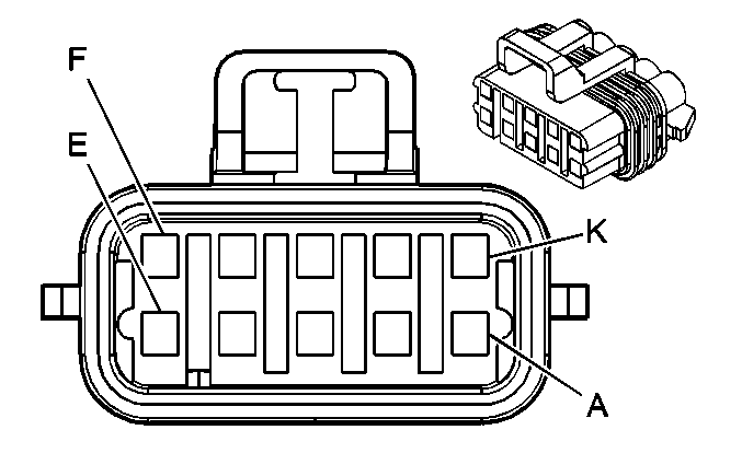
|

| ||||||||||||||
|---|---|---|---|---|---|---|---|---|---|---|---|---|---|---|---|
Connector Part Information |
| Connector Part Information |
| ||||||||||||
Pin | Wire Color | Circuit No. | Function | Pin | Wire Color | Circuit No. | Function | ||||||||
A | -- | -- | Not Used | A | -- | -- | Not Used | ||||||||
B | D-BU | 473 | High Speed Cooling Fan Relay Control | B | D-BU | 473 | High Speed Cooling Fan Relay Control | ||||||||
C | -- | -- | Not Used | C | -- | -- | Not Used | ||||||||
D | OG/BK | 1057 | Low Reference | D | OG/BK | 1057 | Low Reference | ||||||||
E | PK/BK | 109 | Hood Ajar Switch Signal | E | PK/BK | 109 | Hood Ajar Switch Signal | ||||||||
F | -- | -- | Not Used | F | -- | -- | Not Used | ||||||||
G | D-GN | 335 | Low Speed Cooling Fan Relay Control | G | D-GN | 335 | Low Speed Cooling Fan Relay Control | ||||||||
H | L-BU | 703 | Starter/Generator Control Module Coolant Pump Supply Voltage | H | L-BU | 703 | Starter/Generator Control Module Coolant Pump Supply Voltage | ||||||||
J-K | -- | -- | Not Used | J-K | -- | -- | Not Used | ||||||||
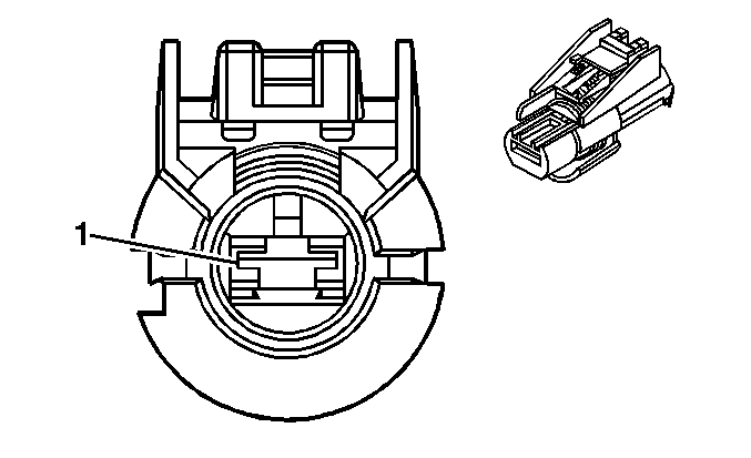
|
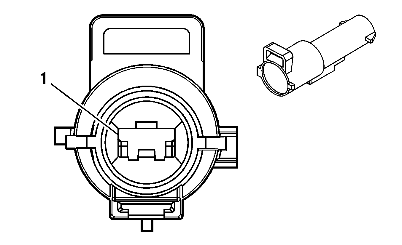
| ||||||||||||||
|---|---|---|---|---|---|---|---|---|---|---|---|---|---|---|---|
Connector Part Information |
| Connector Part Information |
| ||||||||||||
Pin | Wire Color | Circuit No. | Function | Pin | Wire Color | Circuit No. | Function | ||||||||
1 | RD | 5875 | EHPS 42V Battery Voltage | A | RD | 5875 | EHPS 42V Battery Voltage | ||||||||

|

| ||||||||||||||
|---|---|---|---|---|---|---|---|---|---|---|---|---|---|---|---|
Connector Part Information |
| Connector Part Information |
| ||||||||||||
Pin | Wire Color | Circuit No. | Function | Pin | Wire Color | Circuit No. | Function | ||||||||
1 | BK | 5691 | EHPS 42V Ground | A | BK | 5691 | EHPS 42V Ground | ||||||||
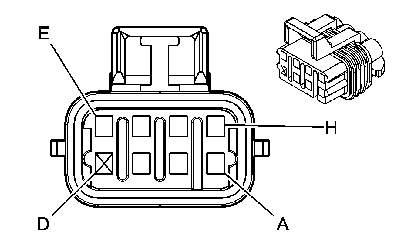
|
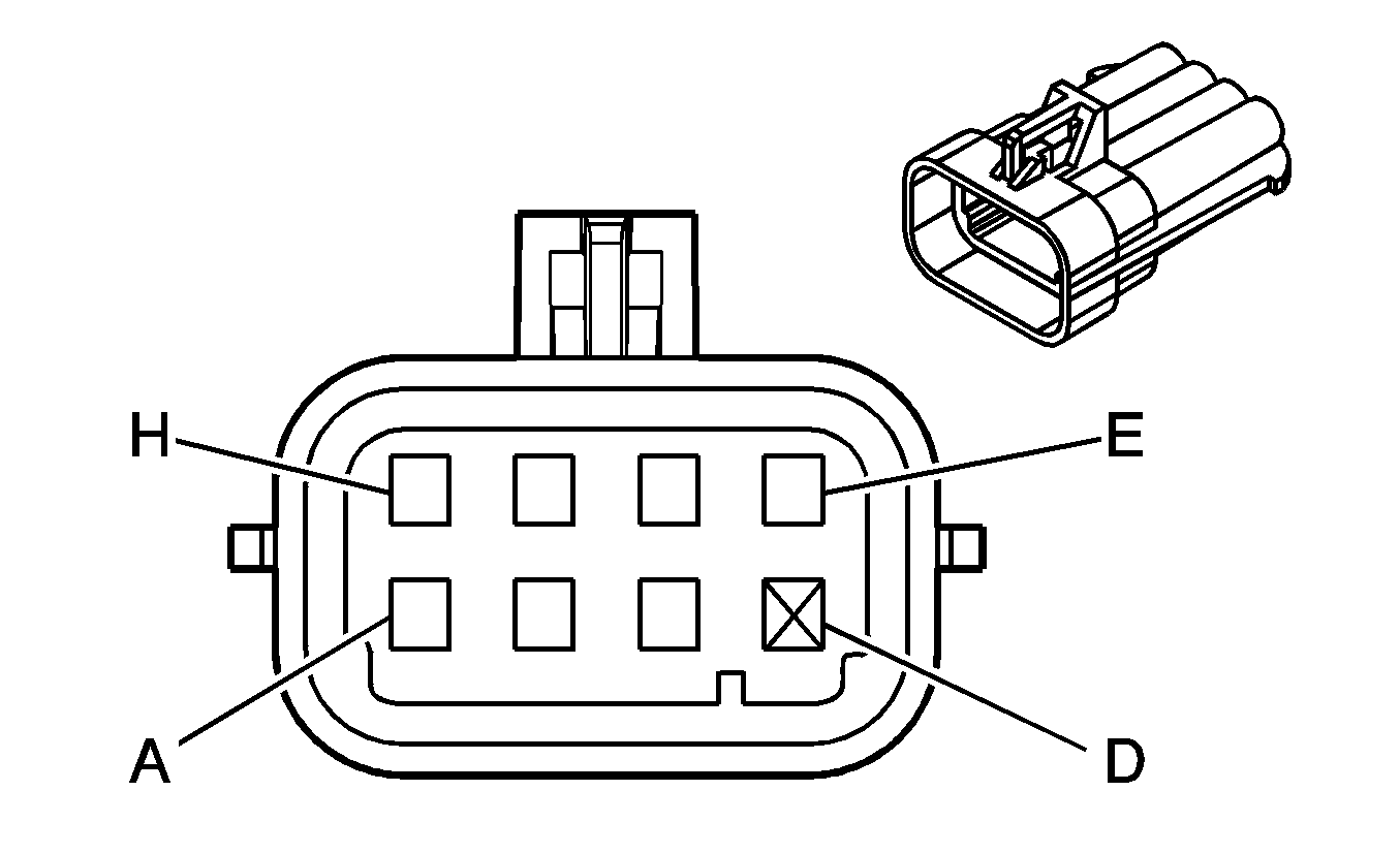
| ||||||||||||||
|---|---|---|---|---|---|---|---|---|---|---|---|---|---|---|---|
Connector Part Information |
| Connector Part Information |
| ||||||||||||
Pin | Wire Color | Circuit No. | Function | Pin | Wire Color | Circuit No. | Function | ||||||||
A | BN | 2309 | Front Park Lamps Supply Voltage | A | BN | 2309 | Front Park Lamps Supply Voltage | ||||||||
B | BN | 2309 | Front Park Lamps Supply Voltage | B | BN | 2309 | Front Park Lamps Supply Voltage | ||||||||
C | L-BU | 2114 | Left Turn Signal Lamps Supply Voltage | C | L-BU | 2114 | Left Turn Signal Lamps Supply Voltage | ||||||||
D | -- | -- | Not Available | D | -- | -- | Not Available | ||||||||
E | L-BU | 2114 | Left Turn Signal Lamps Supply Voltage | E | L-BU | 2114 | Left Turn Signal Lamps Supply Voltage | ||||||||
F | BK | 150 | Ground | F | BK | 150 | Ground | ||||||||
G | D-BU | 545 | DRL Supply Voltage | G | D-BU | 545 | DRL Supply Voltage | ||||||||
H | BK | 150 | Ground | H | BK | 150 | Ground | ||||||||

|

| ||||||||||||||
|---|---|---|---|---|---|---|---|---|---|---|---|---|---|---|---|
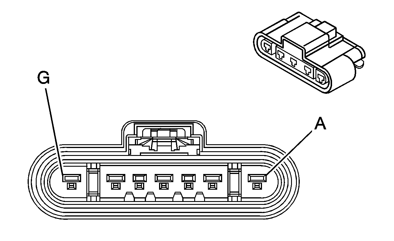
Connector Part Information |
| Connector Part Information |
| ||||||||||||
Pin | Wire Color | Circuit No. | Function | Pin | Wire Color | Circuit No. | Function | ||||||||
A | BN | 2309 | Front Park Lamps Supply Voltage | A | BN | 2309 | Front Park Lamps Supply Voltage | ||||||||
B | BN | 2309 | Front Park Lamps Supply Voltage | B | BN | 2309 | Front Park Lamps Supply Voltage | ||||||||
C | D-BU | 2115 | Right Turn Signal Lamps Supply Voltage | C | D-BU | 2115 | Right Turn Signal Lamps Supply Voltage | ||||||||
D | -- | -- | Not Available | D | -- | -- | Not Available | ||||||||
E | D-BU | 2115 | Right Turn Signal Lamps Supply Voltage | E | D-BU | 2115 | Right Turn Signal Lamps Supply Voltage | ||||||||
F | BK | 150 | Ground | F | BK | 150 | Ground | ||||||||
G | D-BU | 545 | DRL Supply Voltage | G | D-BU | 545 | DRL Supply Voltage | ||||||||
H | BK | 150 | Ground | H | BK | 150 | Ground | ||||||||
|
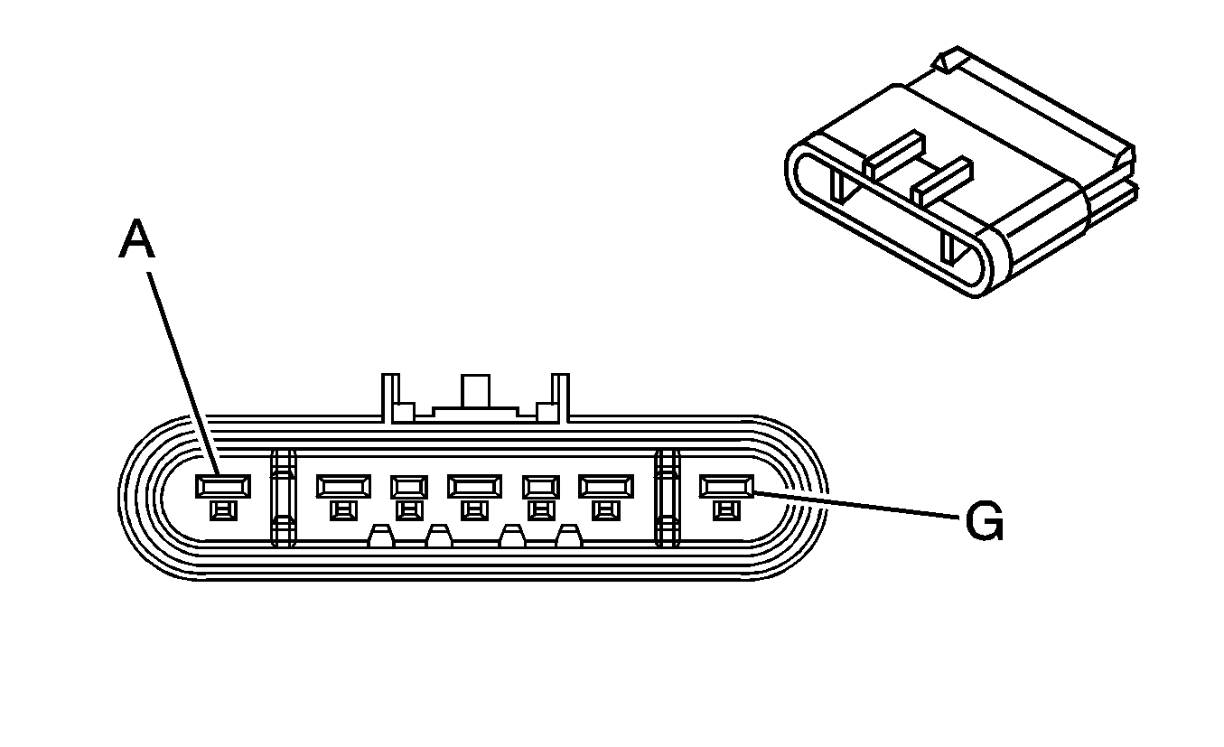
| ||||||||||||||
|---|---|---|---|---|---|---|---|---|---|---|---|---|---|---|---|
Connector Part Information |
| Connector Part Information |
| ||||||||||||
Pin | Wire Color | Circuit No. | Function | Pin | Wire Color | Circuit No. | Function | ||||||||
A | -- | -- | Not Used | A | -- | -- | Not Used | ||||||||
B | WH | 5685 | 120 VAC Neutral | B | WH | 5685 | 120 VAC Neutral | ||||||||
C | OG | 5595 | High Voltage Interlock Loop Signal | C | YE | 5690 | High Voltage Interlock Loop Signal | ||||||||
D | BK | 50 | Ground | D | BK | 50 | Ground | ||||||||
E | PU | 5087 | High Voltage Interlock Loop Signal | E | PU | 5087 | High Voltage Interlock Loop Signal | ||||||||
F | D-GN | 5686 | 120 VAC Ground | F | D-GN | 5686 | 120 VAC Ground | ||||||||
G | BK | 5683 | 120 VAC Phase A | G | BK | 5683 | 120 VAC Phase A | ||||||||

|

| ||||||||||||||
|---|---|---|---|---|---|---|---|---|---|---|---|---|---|---|---|
Connector Part Information |
| Connector Part Information |
| ||||||||||||
Pin | Wire Color | Circuit No. | Function | Pin | Wire Color | Circuit No. | Function | ||||||||
A | -- | -- | Not Used | A | -- | -- | Not Used | ||||||||
B | L-BU | 494 | PTO Engine Kill Signal | B | L-BU | 494 | PTO Engine Kill Signal | ||||||||
C | L-GN | 488 | PTO On Switch-Signal | C | L-GN | 488 | PTO On Switch-Signal | ||||||||
D | BK | 550 | Ground | D | BK | 550 | Ground | ||||||||
E-F | -- | -- | Not Used | E-F | -- | -- | Not Used | ||||||||
G | YE | 2522 | PTO Engage Signal | G | YE | 2522 | PTO Engage Signal | ||||||||
H | WH | 2561 | PTO Supply Voltage | H | WH | 2561 | PTO Supply Voltage | ||||||||
J | D-BU | 84 | Cruise Control Set/Coast Switch Signal | J | D-BU | 84 | Cruise Control Set/Coast Switch Signal | ||||||||
K | -- | -- | Not Used | K | -- | -- | Not Used | ||||||||

|

| ||||||||||||||
|---|---|---|---|---|---|---|---|---|---|---|---|---|---|---|---|
Connector Part Information |
| Connector Part Information |
| ||||||||||||
Pin | Wire Color | Circuit No. | Function | Pin | Wire Color | Circuit No. | Function | ||||||||
A | BK | 550 | Ground | A | BK | 550 | Ground | ||||||||
B | RD | 2127 | IC 7 Control | B | RD | 2127 | IC 7 Control | ||||||||
C | D-GN | 2125 | IC 5 Control | C | D-GN | 2125 | IC 5 Control | ||||||||
D | -- | -- | Not Available | D | -- | -- | Not Available | ||||||||
E | BN | 2129 | Low Reference | E | BN | 2129 | Low Reference | ||||||||
F | L-BU | 2123 | IC 3 Control | F | L-BU | 2123 | IC 3 Control | ||||||||
G | PU | 2121 | IC 1 Control | G | PU | 2121 | IC 1 Control | ||||||||
H | PK | 1039 | Ignition 1 Voltage | H | PK | 1039 | Ignition 1 Voltage | ||||||||

|

| ||||||||||||||
|---|---|---|---|---|---|---|---|---|---|---|---|---|---|---|---|
Connector Part Information |
| Connector Part Information |
| ||||||||||||
Pin | Wire Color | Circuit No. | Function | Pin | Wire Color | Circuit No. | Function | ||||||||
A | BK | 550 | Ground | A | BK | 550 | Ground | ||||||||
B | RD/WH | 2122 | IC 2 Control | B | RD | 2122 | IC 2 Control | ||||||||
C | D-GN/WH | 2124 | IC 4 Control | C | D-GN | 2124 | IC 4 Control | ||||||||
D | -- | -- | Not Available | D | -- | -- | Not Available | ||||||||
E | BN/WH | 2130 | Low Reference | E | BN | 2130 | Low Reference | ||||||||
F | L-BU/WH | 2126 | IC 6 Control | F | L-BU | 2126 | IC 6 Control | ||||||||
G | PU/WH | 2128 | IC 8 Control | G | PU | 2128 | IC 8 Control | ||||||||
H | PK | 1239 | Ignition 1 Voltage | H | PK | 1239 | Ignition 1 Voltage | ||||||||
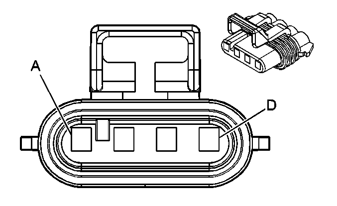
|
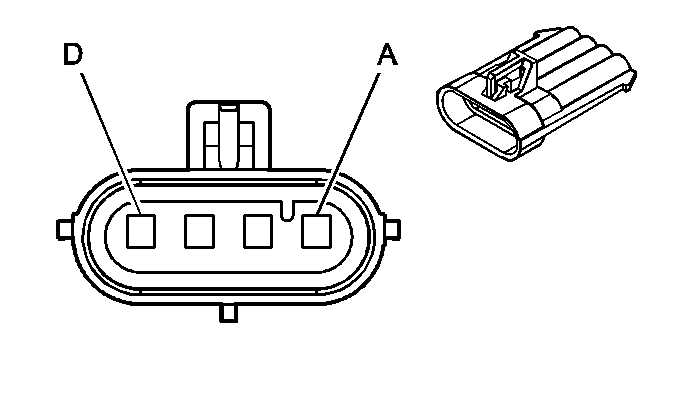
| ||||||||||||||
|---|---|---|---|---|---|---|---|---|---|---|---|---|---|---|---|
Connector Part Information |
| Connector Part Information |
| ||||||||||||
Pin | Wire Color | Circuit No. | Function | Pin | Wire Color | Circuit No. | Function | ||||||||
A | BK/WH | 1695 | Axle Switch Signal | A | BK/WH | 1695 | Axle Switch Signal | ||||||||
B | L-BU | 1296 | Axle Actuator - Control | B | L-BU | 1296 | Axle Actuator - Control | ||||||||
C | BN | 241 | Ignition 3 Voltage | C | BN | 241 | Ignition 3 Voltage | ||||||||
D | BK | 2150 | Ground | D | BK | 2150 | Ground | ||||||||
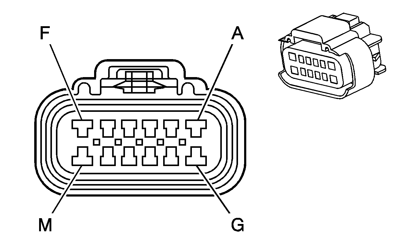
|
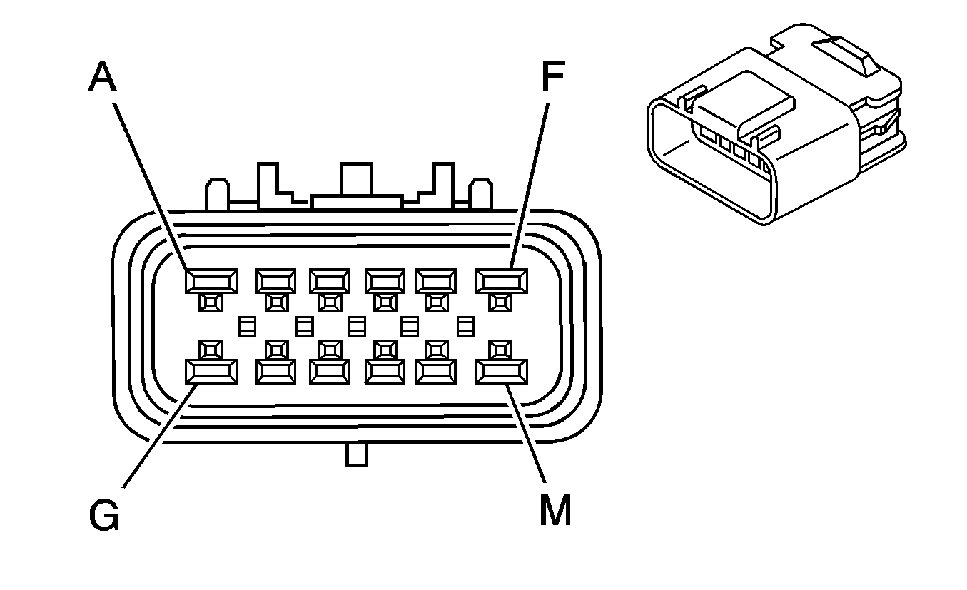
| ||||||||||||||
|---|---|---|---|---|---|---|---|---|---|---|---|---|---|---|---|
Connector Part Information |
| Connector Part Information |
| ||||||||||||
Pin | Wire Color | Circuit No. | Function | Pin | Wire Color | Circuit No. | Function | ||||||||
A | BK | 2150 | Ground | A | BK | 2150 | Ground | ||||||||
B | BK/WH | 1695 | Axle Switch Signal | B | BK/WH | 1695 | Axle Switch Signal | ||||||||
C | L-BU | 1296 | Axle Actuator Control | C | L-BU | 1296 | Axle Actuator Control | ||||||||
D | GY/BK | 1694 | 4WD Low Signal | D | GY/BK | 1694 | 4WD Low Signal | ||||||||
E | BN/WH | 1555 | Encoder Signal | E | BN/WH | 1555 | Encoder Signal | ||||||||
F | BK | 1552 | Motor Control A | F | BK | 1552 | Motor Control A | ||||||||
G | RD | 1553 | Motor Control B | G | RD | 1553 | Motor Control B | ||||||||
H | YE | 400 | Signal High - Front (NP8) | H | YE | 400 | Signal High - Front (NP8) | ||||||||
J | PU | 401 | Signal Low - Front (NP8) | J | PU | 401 | Signal Low - Front (NP8) | ||||||||
K | L-BU | 2221 | Signal High - Rear (NP8) | K | L-BU | 2221 | Signal High - Rear (NP8) | ||||||||
L | D-GN | 2222 | Signal Low - Rear (NP8) | L | D-GN | 2222 | Signal Low - Rear (NP8) | ||||||||
M | OG | 1640 | Battery Positive Voltage (NP8) | M | OG | 1640 | Battery Positive Voltage (NP8) | ||||||||
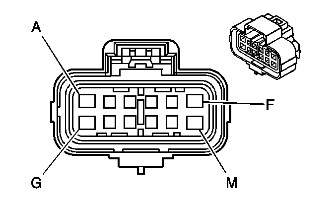
|
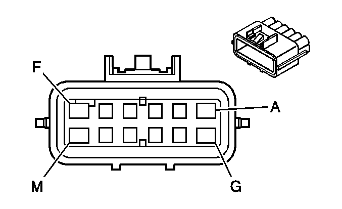
| ||||||||||||||
|---|---|---|---|---|---|---|---|---|---|---|---|---|---|---|---|
Connector Part Information |
| Connector Part Information |
| ||||||||||||
Pin | Wire Color | Circuit No. | Function | Pin | Wire Color | Circuit No. | Function | ||||||||
A | -- | -- | Not Used | A | -- | -- | Not Used | ||||||||
B | TN | 1465 | Fuel Pump Relay Control - Secondary - Dual Fuel Tanks (Gas) | B | TN | 1465 | Fuel Pump Relay Control - Secondary - Dual Fuel Tanks (Gas) | ||||||||
C | GY | 474 | 5-Volt Reference (Gas) | C | GY | 474 | 5-Volt Reference (Gas) | ||||||||
D | D-GN | 890 | Fuel Tank Pressure Sensor Signal (Gas) | D | D-GN | 890 | Fuel Tank Pressure Sensor Signal (Gas) | ||||||||
E | YE/BK | 1827 | Vehicle Speed Signal | E | YE/BK | 1827 | Vehicle Speed Signal | ||||||||
F | WH | 1310 | EVAP Canister Vent Solenoid Control (Gas) | F | WH | 1310 | EVAP Canister Vent Solenoid Control (Gas) | ||||||||
G | -- | -- | Not Used | G | -- | -- | Not Used | ||||||||
H | D-BU | 1936 | Fuel Level Sensor Signal - Secondary - Dual Fuel Tanks | H | D-BU | 1936 | Fuel Level Sensor Signal - Secondary - Dual Fuel Tanks | ||||||||
J | BK | 470 | Low Reference | J | BK | 470 | Low Reference | ||||||||
K | PU | 1589 | Fuel Level Sensor Signal - Primary | K | PU | 1589 | Fuel Level Sensor Signal - Primary (8.1L/HP2) | ||||||||
PU/WH | 1589 | Fuel Level Sensor Signal - Primary (All Others) | |||||||||||||
L | TN/BK | 464 | Delivered Torque Signal (NW7) | L | TN/BK | 464 | Delivered Torque Signal (NW7) | ||||||||
M | OG/BK | 463 | Requested Torque Signal | M | OG/BK | 463 | Requested Torque Signal (NW7) | ||||||||
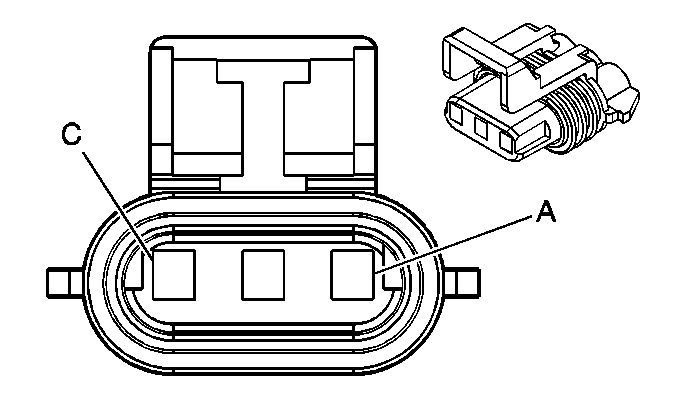
|
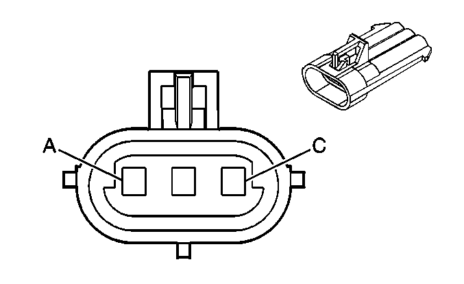
| ||||||||||||||
|---|---|---|---|---|---|---|---|---|---|---|---|---|---|---|---|
Connector Part Information |
| Connector Part Information |
| ||||||||||||
Pin | Wire Color | Circuit No. | Function | Pin | Wire Color | Circuit No. | Function | ||||||||
A | GY/BK | 1694 | 4WD Low Signal | A | GY/BK | 1694 | 4WD Low Signal | ||||||||
B | BK/WH | 1695 | Axle Switch Signal (NP2) | B | BK/WH | 1695 | Axle Switch Signal | ||||||||
C | BN | 241 | Ignition 3 Voltage | C | BN | 241 | Ignition 3 Voltage | ||||||||
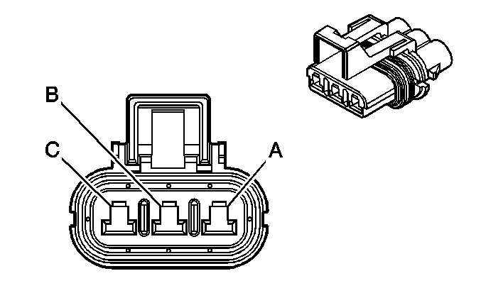
|
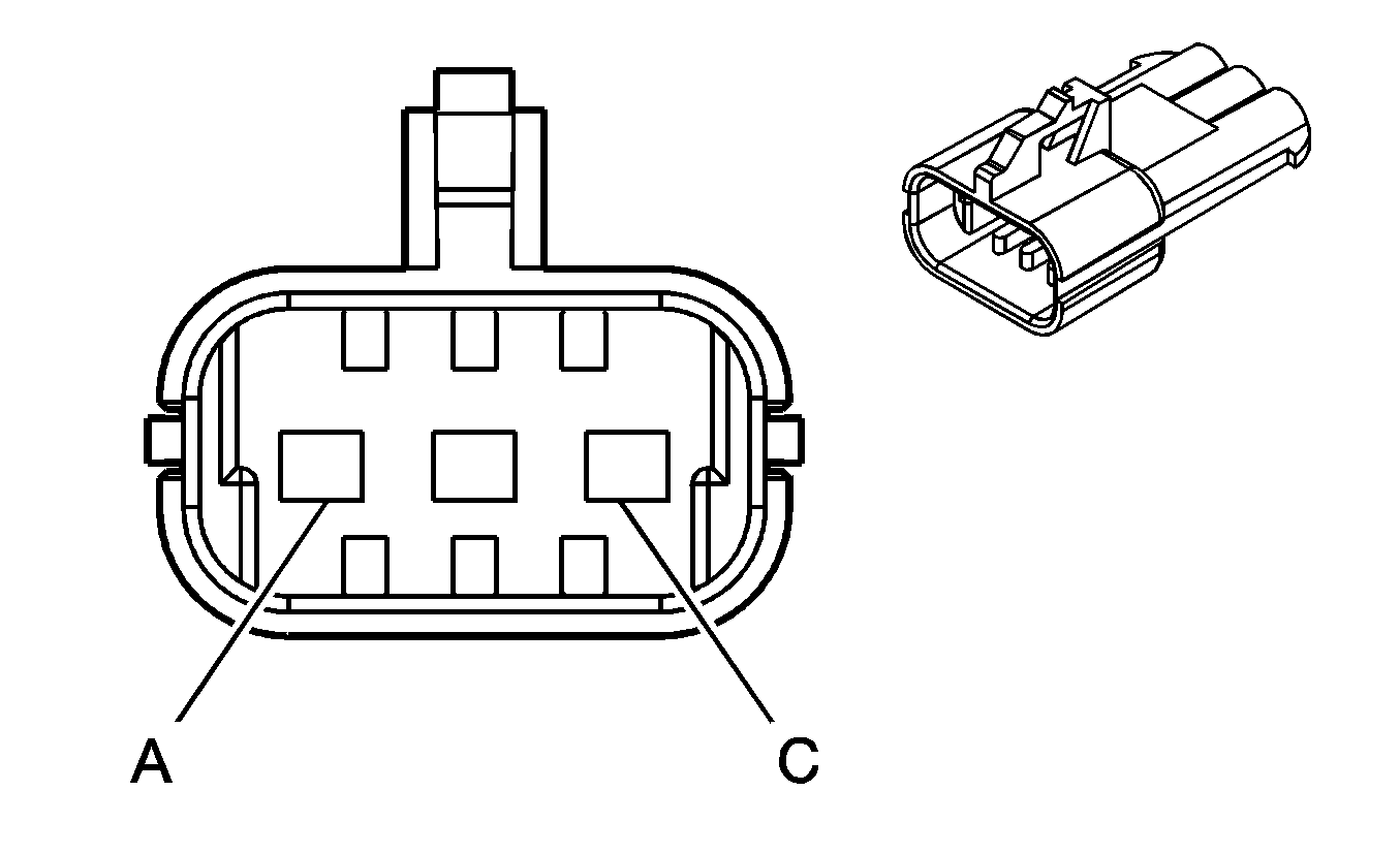
| ||||||||||||||
|---|---|---|---|---|---|---|---|---|---|---|---|---|---|---|---|
Connector Part Information |
| Connector Part Information |
| ||||||||||||
Pin | Wire Color | Circuit No. | Function | Pin | Wire Color | Circuit No. | Function | ||||||||
A | L-GN/BK | 431 | 5-Volt Reference | A | L-GN/BK | 431 | 5-Volt Reference | ||||||||
B | TN | 1569 | Lock Solenoid Control (NP8) | B | TN | 1569 | Lock Solenoid Control (NP8) | ||||||||
C | BK/WH | 1554 | Encoder Low Reference | C | BK/WH | 1554 | Encoder Low Reference | ||||||||

|

| ||||||||||||||
|---|---|---|---|---|---|---|---|---|---|---|---|---|---|---|---|
Connector Part Information |
| Connector Part Information |
| ||||||||||||
Pin | Wire Color | Circuit No. | Function | Pin | Wire Color | Circuit No. | Function | ||||||||
A | BK | 1744 | Fuel Injector 1 Control | A | BK | 1744 | Fuel Injector 1 Control | ||||||||
B | D-BU/WH | 878 | Fuel Injector 8 Control | B | D-BU/WH | 878 | Fuel Injector 8 Control | ||||||||
C | L-BU/BK | 844 | Fuel Injector 4 Control | C | L-BU/BK | 844 | Fuel Injector 4 Control | ||||||||
D | PK/BK | 1746 | Fuel Injector 3 Control | D | PK/BK | 1746 | Fuel Injector 3 Control | ||||||||
E | YE/BK | 846 | Fuel Injector 6 Control | E | YE/BK | 846 | Fuel Injector 6 Control | ||||||||
F | BK/WH | 845 | Fuel Injector 5 Control | F | BK/WH | 845 | Fuel Injector 5 Control | ||||||||
G | RD/BK | 877 | Fuel Injector 7 Control | G | RD/BK | 877 | Fuel Injector 7 Control | ||||||||
H | L-GN/BK | 1745 | Fuel Injector 2 Control | H | L-GN/BK | 1745 | Fuel Injector 2 Control | ||||||||
J | PK | 1039 | Ignition 1 Voltage | J | PK | 1039 | Ignition 1 Voltage | ||||||||
K | PK | 1239 | Ignition 1 Voltage | K | PK | 1239 | Ignition 1 Voltage | ||||||||

|
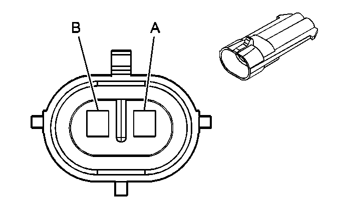
| ||||||||||||||
|---|---|---|---|---|---|---|---|---|---|---|---|---|---|---|---|
Connector Part Information |
| Connector Part Information |
| ||||||||||||
Pin | Wire Color | Circuit No. | Function | Pin | Wire Color | Circuit No. | Function | ||||||||
A | WH | 111 | SEO Relay Switch Signal | A | WH | 111 | SEO Relay Switch Signal | ||||||||
B | BK | 1050 | Ground | B | BK | 1050 | Ground | ||||||||
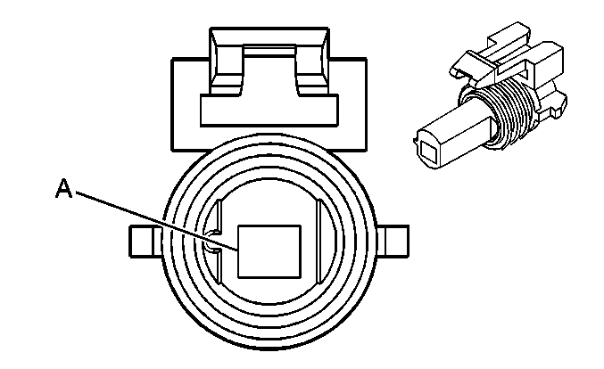
|
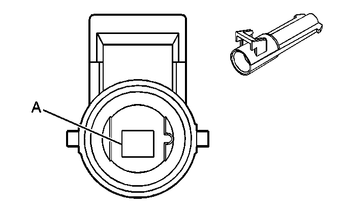
| ||||||||||||||
|---|---|---|---|---|---|---|---|---|---|---|---|---|---|---|---|
Connector Part Information |
| Connector Part Information |
| ||||||||||||
Pin | Wire Color | Circuit No. | Function | Pin | Wire Color | Circuit No. | Function | ||||||||
A | BN | 27 | Hazard Flasher Signal | A | BN | 27 | Hazard Flasher Signal | ||||||||
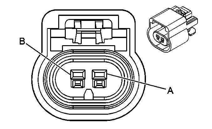
|
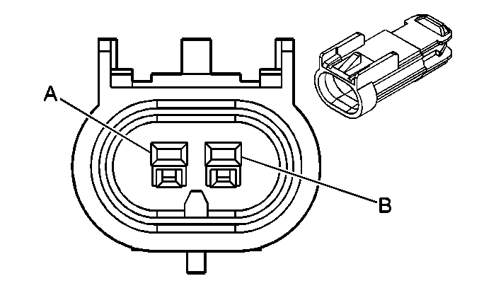
| ||||||||||||||
|---|---|---|---|---|---|---|---|---|---|---|---|---|---|---|---|
Connector Part Information |
| Connector Part Information |
| ||||||||||||
Pin | Wire Color | Circuit No. | Function | Pin | Wire Color | Circuit No. | Function | ||||||||
A | D-BU | 473 | High Speed Cooling Fan Relay Control | A | D-BU | 473 | High Speed Cooling Fan Relay Control | ||||||||
B | D-GN | 335 | Low Speed Cooling Fan Relay Control | B | D-GN | 335 | Low Speed Cooling Fan Relay Control | ||||||||

|

| ||||||||||||||
|---|---|---|---|---|---|---|---|---|---|---|---|---|---|---|---|
Connector Part Information |
| Connector Part Information |
| ||||||||||||
Pin | Wire Color | Circuit No. | Function | Pin | Wire Color | Circuit No. | Function | ||||||||
A | D-BU | 47 | Trailer Auxiliary Supply Voltage | A | D-BU | 47 | Trailer Auxiliary Supply Voltage | ||||||||
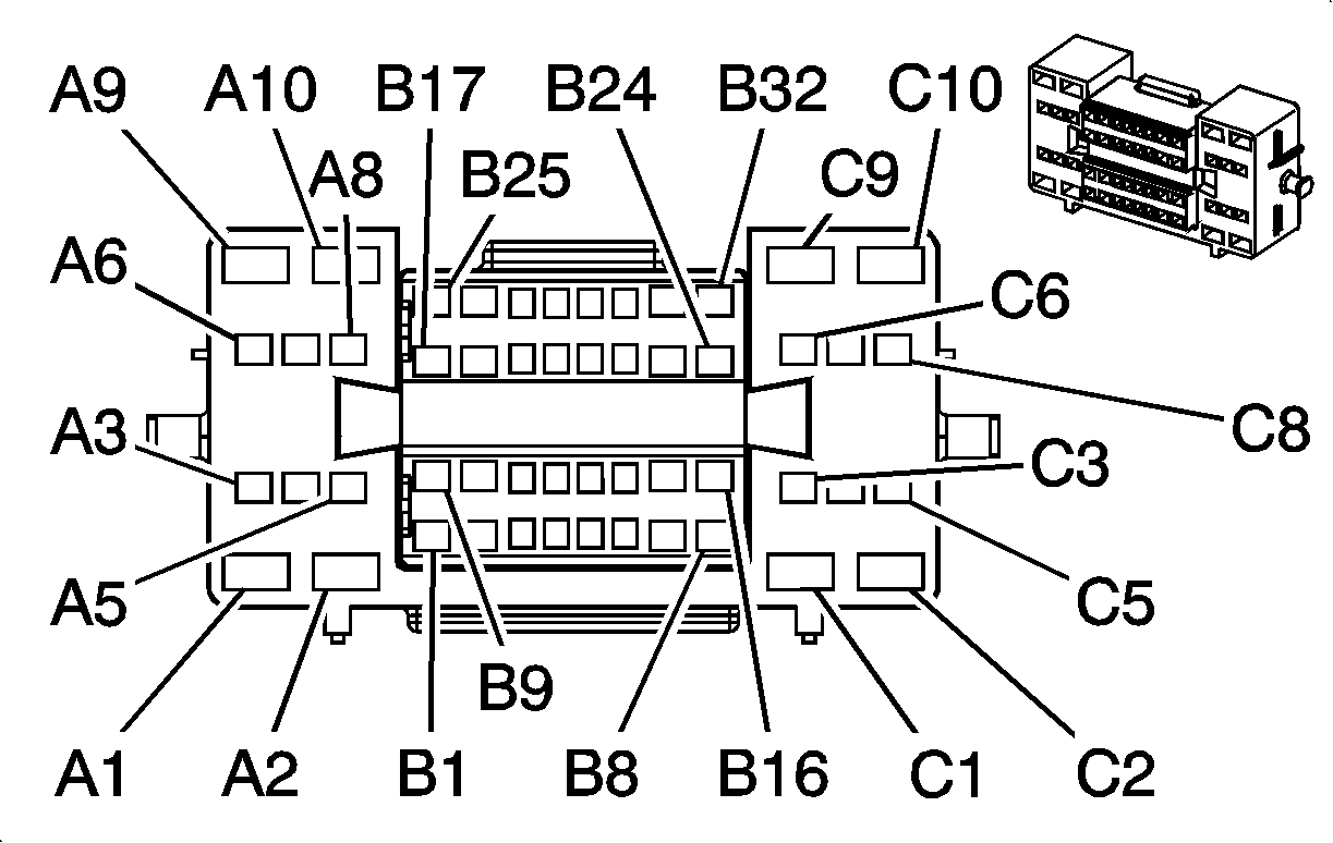
|
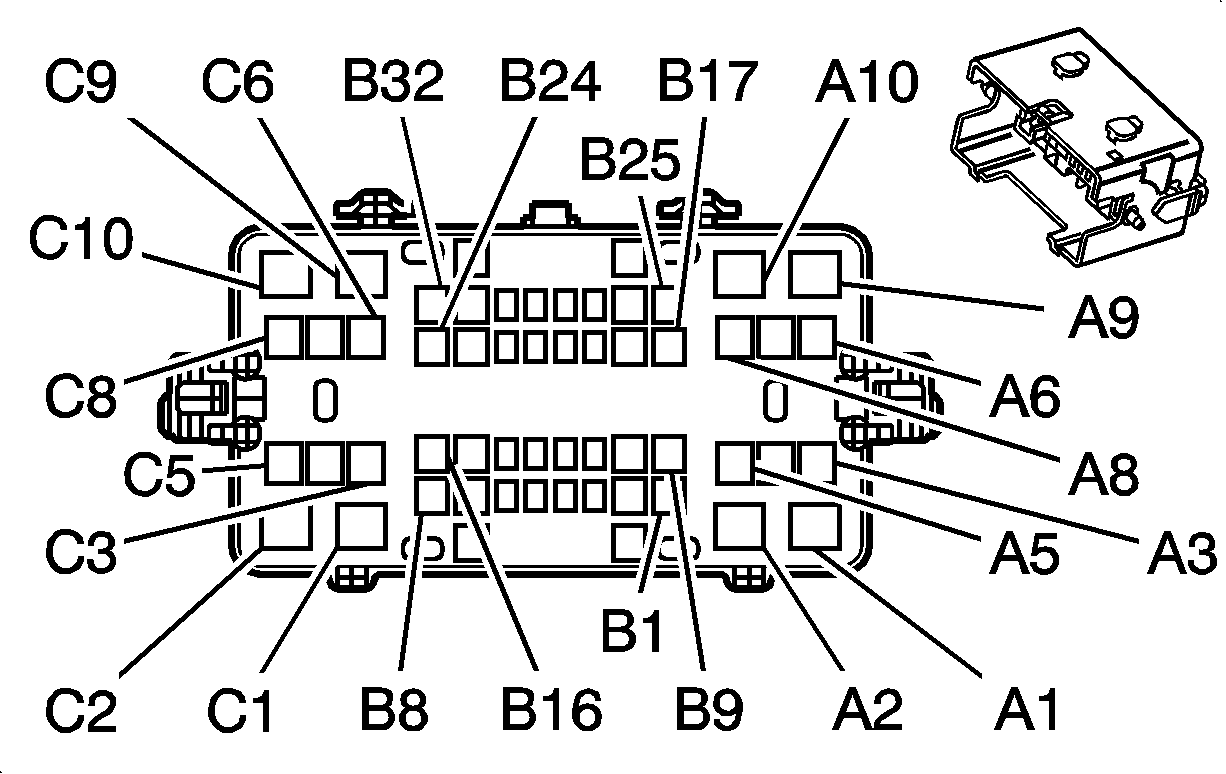
| ||||||||||||||
|---|---|---|---|---|---|---|---|---|---|---|---|---|---|---|---|
Connector Part Information |
| Connector Part Information |
| ||||||||||||
Pin | Wire Color | Circuit No. | Function | Pin | Wire Color | Circuit No. | Function | ||||||||
A1 | -- | -- | Not Used | A1 | -- | -- | Not Used | ||||||||
A2 | PK | 3 | Ignition 1 Voltage | A2 | PK | 3 | Ignition 1 Voltage | ||||||||
A3 | L-GN | 1763 | Steering Wheel Position Signal A (NYS/HP2) | A3 | L-GN | 1763 | Steering Wheel Position Signal A (NYS/HP2) | ||||||||
A4 | PU | 1358 | DIC Switch Signal (UK3) | A4 | D-GN/WH | 1358 | DIC Switch Signal (UK3) | ||||||||
A5 | BK/WH | 1851 | Ground | A5 | BK/WH | 1851 | Ground | ||||||||
BK/WH | 1851 | Ground (HP2) | |||||||||||||
A6 | L-BU | 1764 | Steering Wheel Position Signal B (NYS/HP2) | A6 | L-BU | 1764 | Steering Wheel Position Signal B (NYS/HP2) | ||||||||
A7 | WH | 1765 | Steering Wheel Position Signal - Marker Pulse (NYS) | A7 | WH | 1765 | Steering Wheel Position Signal - Marker Pulse (NYS) | ||||||||
A8 | PK | 639 | Ignition 1 Voltage | A8 | PK | 639 | Ignition 1 Voltage | ||||||||
A9 | -- | -- | Not Used | A9 | -- | -- | Not Used | ||||||||
A10 | RD | 142 | Battery Positive Voltage | A10 | RD | 142 | Battery Positive Voltage | ||||||||
B1 | GY/BK | 87 | Cruise Control Resume/Accel Switch Signal (K34) | B1 | GY/BK | 87 | Cruise Control Resume/Accel Switch Signal (K34) | ||||||||
B2 | YE | 1327 | DIC Fuel Signal (UK3) | B2 | YE | 1327 | DIC Fuel Signal (UK3) | ||||||||
B3 | BK | 28 | Horn Relay Control | B3 | BK | 28 | Horn Relay Control | ||||||||
B4 | L-BU | 1059 | Steering Wheel Position Sensor Signal (NYS) | B4 | L-BU | 1059 | Steering Wheel Position Sensor Signal (NYS) | ||||||||
B5 | L-BU | 553 | Tow/Haul Switch Signal | B5 | L-BU | 553 | Tow/Haul Switch Signal | ||||||||
B6 | BN/WH | 230 | Instrument Panel Lamps Dimming Control (UK3) | B6 | BN/WH | 230 | Instrument Panel Lamps Dimming Control (UK3) | ||||||||
B7 | YE | 143 | Accessory Voltage | B7 | YE | 143 | Accessory Voltage | ||||||||
B8 | BK | 1050 | Ground | B8 | BK | 1050 | Ground | ||||||||
B9 | BK/WH | 1851 | Ground | B9 | BK/WH | 1851 | Ground | ||||||||
B10 | D-BU | 84 | Cruise Control Set/Coast Switch Signal (K34) | B10 | D-BU | 84 | Cruise Control Set/Coast Switch Signal (K34) | ||||||||
B11 | -- | -- | Not Used | B11 | -- | -- | Not Used | ||||||||
B12 | PK | 1796 | Steering Wheel Controls Signal (UK3) | B12 | D-BU | 1796 | Steering Wheel Controls Signal (UK3) | ||||||||
B13 | OG/BK | 1816 | DIC Set/Reset Switch Signal (UK3) | B13 | OG | 1816 | DIC Set/Reset Switch Signal (UK3) | ||||||||
B14 | D-GN | 1932 | Transmission Shift Select Switch (Park) Signal (A/T) | B14 | D-GN/WH | 1932 | Transmission Shift Select Switch (Park) Signal (A/T) | ||||||||
B15 | PK | 94 | Windshield Wiper Switch Signal 1 | B15 | PK | 94 | Windshield Wiper Switch Signal 1 | ||||||||
B16 | YE | 307 | Headlamp Switch Flash to Pass Signal | B16 | YE | 307 | Headlamp Switch Flash to Pass Signal | ||||||||
B17 | L-GN/BK | 11 | Headlamp High Beam Supply Voltage | B17 | L-GN | 11 | Headlamp High Beam Supply Voltage | ||||||||
B18 | BN | 41 | Ignition 3 Voltage | B18 | BN | 41 | Ignition 3 Voltage | ||||||||
B19-B22 | -- | -- | Not Used | B19-B22 | -- | -- | Not Used | ||||||||
B23 | GY | 1056 | Steering Wheel Position Sensor 5-Volt Reference Voltage (NYS/HP2) | B23 | GY | 1056 | Steering Wheel Position Sensor 5-Volt Reference Voltage (NYS/HP2) | ||||||||
B24 | D-BU | 477 | Windshield Wiper Switch High Signal | B24 | D-BU | 477 | Windshield Wiper Switch High Signal | ||||||||
B25 | L-GN | 80 | Key In Ignition Switch Signal | B25 | L-GN | 80 | Key In Ignition Switch Signal | ||||||||
B26 | D-BU | 894 | DIC Toggle Switch Signal (UK3) | B26 | D-BU | 894 | DIC Toggle Switch Signal (UK3) | ||||||||
B27 | BK | 1835 | Security System Sensor Low Reference | B27 | BK | 1835 | Security System Sensor Low Reference | ||||||||
B28 | YE | 1836 | Security System Sensor Signal | B28 | YE | 1836 | Security System Sensor Signal | ||||||||
B29 | RD/WH | 812 | 12-Volt Reference | B29 | RD/WH | 812 | 12-Volt Reference | ||||||||
B30 | D-GN/WH | 1135 | A/T Shift Lock Control Solenoid Supply Voltage (A/T) | B30 | D-GN/WH | 1135 | A/T Shift Lock Control Solenoid Supply Voltage (A/T) | ||||||||
B31 | L-GN | 1011 | Remote Radio Control Signal (UK3) | B31 | L-GN | 1011 | Remote Radio Control Signal (UK3) | ||||||||
B32 | GY | 397 | Cruise Control On Switch Signal (K34) | B32 | GY | 397 | Cruise Control On Switch Signal (K34) | ||||||||
C1 | RD | 342 | Battery Positive Voltage | C1 | RD | 342 | Battery Positive Voltage | ||||||||
C2-C8 | -- | -- | Not Used | C2-C8 | -- | -- | Not Used | ||||||||
C9 | YE | 5 | Crank Voltage | C9 | YE | 5 | Crank Voltage | ||||||||
C10 | -- | -- | Not Used | C10 | -- | -- | Not Used | ||||||||
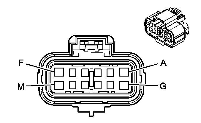
|
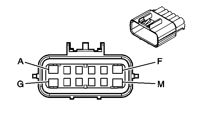
| ||||||||||||||
|---|---|---|---|---|---|---|---|---|---|---|---|---|---|---|---|
Connector Part Information |
| Connector Part Information |
| ||||||||||||
Pin | Wire Color | Circuit No. | Function | Pin | Wire Color | Circuit No. | Function | ||||||||
A | PU | 420 | TCC Brake Switch /Cruise Control Release Signal (K34) | A | PU | 420 | TCC Brake Switch /Cruise Control Release Signal (K34) | ||||||||
PU | 420 | TCC Brake Switch /Cruise Control Release Signal (4.3L w/K34) | |||||||||||||
B | D-GN | 1433 | Clutch Start Switch Signal (M/T) | B | D-GN | 1433 | Clutch Start Switch Signal (M/T) | ||||||||
GY/BK | 5689 | Low Reference (HP2) | GY/BK | 5689 | Low Reference (HP2) | ||||||||||
C | PK | 639 | Ignition 1 Voltage (w/o HP2) | C | PK | 639 | Ignition 1 Voltage (w/o HP2) | ||||||||
YE | 5066 | Brake Pedal Position Sensor Signal (HP2) | YE | 5066 | Brake Pedal Position Sensor Signal (HP2) | ||||||||||
D | D-GN/WH | 1135 | A/T Shift Lock Control Solenoid Supply Voltage | D | D-GN/WH | 1135 | A/T Shift Lock Control Solenoid Supply Voltage | ||||||||
E | L-GN/BK | 584 | A/T Shift Lock Control Switch Supply Voltage | E | L-GN/BK | 584 | A/T Shift Lock Control Switch Supply Voltage | ||||||||
F | BN | 441 | Ignition 3 Voltage | F | BN | 441 | Ignition 3 Voltage | ||||||||
G | OG | 1540 | Battery Positive Voltage | G | OG | 1540 | Battery Positive Voltage | ||||||||
H | WH | 17 | Stop Lamp Switch Signal | H | WH | 17 | Stop Lamp Switch Signal | ||||||||
J | L-BU | 1134 | Park Brake Switch Signal | J | L-BU | 1134 | Park Brake Switch Signal | ||||||||
K | GY | 48 | CPP Switch Signal (M/T) | K | GY | 48 | CPP Switch Signal (M/T) | ||||||||
OG | 5688 | 5-Volt Reference (HP2) | OG | 5688 | 5-Volt Reference (HP2) | ||||||||||
L-M | -- | -- | Not Used | L-M | -- | -- | Not Used | ||||||||
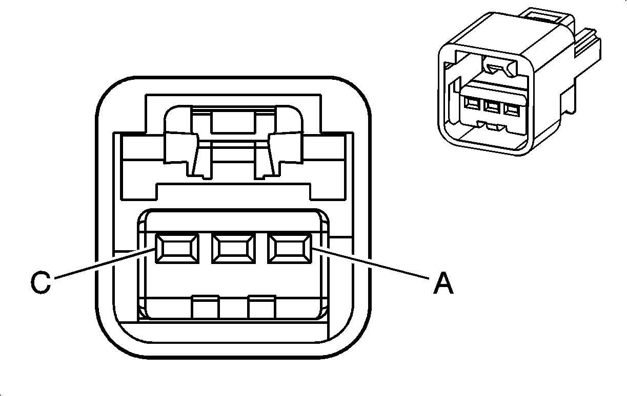
|
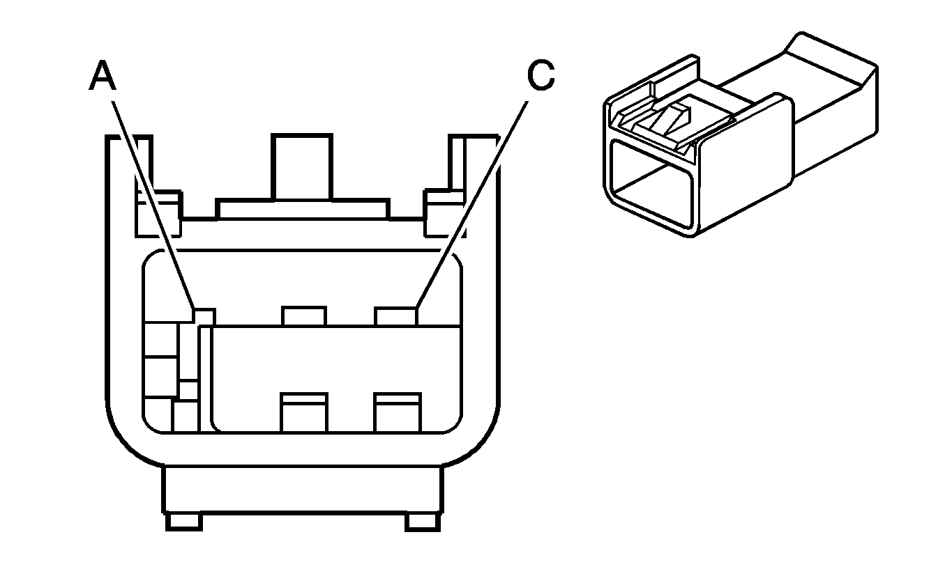
| ||||||||||||||
|---|---|---|---|---|---|---|---|---|---|---|---|---|---|---|---|
Connector Part Information |
| Connector Part Information |
| ||||||||||||
Pin | Wire Color | Circuit No. | Function | Pin | Wire Color | Circuit No. | Function | ||||||||
A | OG | 5688 | Brake Pedal Position Sensor 5-Volt Supply | A | RD | 5688 | Brake Pedal Position Sensor 5-Volt Supply | ||||||||
B | YE | 5066 | Brake Pedal Position Sensor Signal | B | D-BU | 5066 | Brake Pedal Position Sensor Signal | ||||||||
C | GY/BK | 5689 | Brake Pedal Position Sensor 5-Volt Return | C | WH | 5689 | Brake Pedal Position Sensor 5-Volt Return | ||||||||
|
| ||||||||||||||
|---|---|---|---|---|---|---|---|---|---|---|---|---|---|---|---|
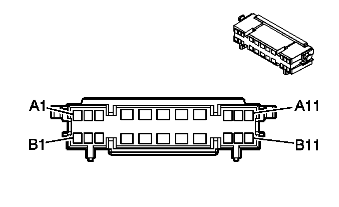
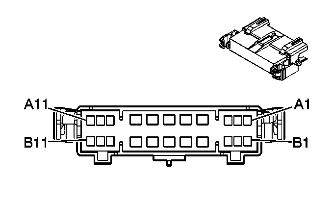
Connector Part Information |
| Connector Part Information |
| ||||||||||||
Pin | Wire Color | Circuit No. | Function | Pin | Wire Color | Circuit No. | Function | ||||||||
A1 | -- | -- | Not Used | A1 | -- | -- | Not Used | ||||||||
A2 | YE | 354 | Discriminating Sensor - Signal | A2 | YE | 354 | Discriminating Sensor - Signal | ||||||||
A3 | GY | 349 | Discriminating Sensor - Left - Signal | A3 | GY | 349 | Discriminating Sensor - Left - Signal | ||||||||
A4 | L-BU | 115 | Right Rear Speaker Output (-) | A4 | L-BU | 115 | Right Rear Speaker Output (-) | ||||||||
A5 | D-BU | 46 | Right Rear Speaker Output (+) | A5 | D-BU | 46 | Right Rear Speaker Output (+) | ||||||||
A6 | TN/WH | 2500 | High Speed GMLAN Serial Data Bus+ (HP2) | A6 | TN/WH | 2500 | High Speed GMLAN Serial Data Bus+ (HP2) | ||||||||
TN/WH | 2500 | High Speed GMLAN Serial Data Bus+ (HP2) | |||||||||||||
A7 | YE | 116 | Left Rear Speaker Output (-) | A7 | YE | 116 | Left Rear Speaker Output (-) | ||||||||
A8 | BN | 199 | Left Rear Speaker Output (+) | A8 | BN | 199 | Left Rear Speaker Output (+) | ||||||||
A9 | YE | 1834 | Forward Discriminating Sensor Signal | A9 | YE | 1834 | Forward Discriminating Sensor Signal | ||||||||
A10-A11 | -- | -- | Not Used | A10-A11 | -- | -- | Not Used | ||||||||
B1 | D-GN | 1409 | Discriminating Sensor - Right - Signal | B1 | D-GN | 1409 | Discriminating Sensor - Right - Signal | ||||||||
B2 | D-GN | 2164 | Side Impact Sensor - Right - Signal (HP2) | B2 | D-GN | 2164 | Side Impact Sensor - Right - Signal (HP2) | ||||||||
B3 | TN | 2163 | Side Impact Sensor - Right - Voltage (HP2) | B3 | TN | 2163 | Side Impact Sensor - Right - Voltage (HP2) | ||||||||
B4 | TN | 2501 | High Speed GMLAN Serial Data Bus - (HP2) | B4 | TN | 2501 | High Speed GMLAN Serial Data Bus - (HP2) | ||||||||
TN | 2501 | High Speed GMLAN Serial Data Bus - (HP2) | |||||||||||||
B5 | D-BU/WH | 2218 | Serial Communications Circuit | B5 | D-BU/WH | 2218 | Serial Communications Circuit | ||||||||
B6 | PK | 1020 | Ignition 0 Voltage (HP2) | B6 | PK | 1020 | Ignition 0 Voltage (HP2) | ||||||||
B7 | PK | 1939 | Ignition 1 Voltage (HP2) | B7 | PK | 1939 | Ignition 1 Voltage (HP2) | ||||||||
B8 | -- | -- | Not Used | B8 | -- | -- | Not Used | ||||||||
B9 | OG | 2740 | Battery Positive Voltage (HP2) | B9 | OG | 2740 | Battery Positive Voltage (HP2) | ||||||||
B10-B11 | -- | -- | Not Used | B10-B11 | -- | -- | Not Used | ||||||||
|
| ||||||||||||||
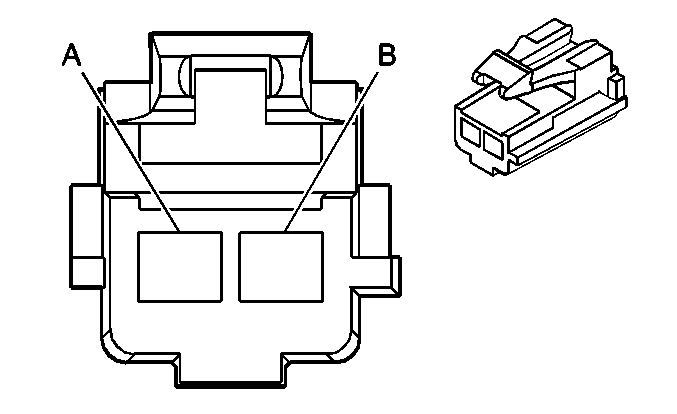
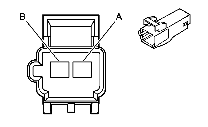
|---|---|---|---|---|---|---|---|---|---|---|---|---|---|---|---|
Connector Part Information |
| Connector Part Information |
| ||||||||||||
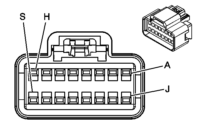
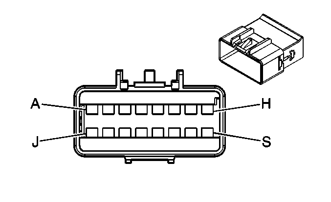
Pin | Wire Color | Circuit No. | Function | Pin | Wire Color | Circuit No. | Function | ||||||||
A | OG | 2340 | Battery Positive Voltage | A | OG | 2340 | Battery Positive Voltage | ||||||||
B | WH | 111 | Hazard Switch Signal | B | WH | 111 | Hazard Switch Signal | ||||||||
|
| ||||||||||||||
|---|---|---|---|---|---|---|---|---|---|---|---|---|---|---|---|
Connector Part Information |
| Connector Part Information |
| ||||||||||||
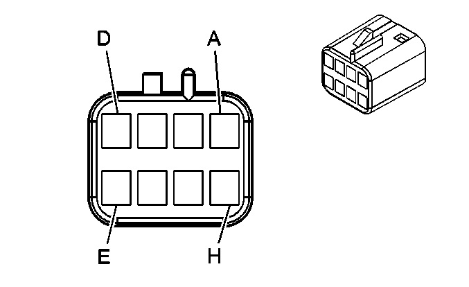
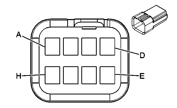
Pin | Wire Color | Circuit No. | Function | Pin | Wire Color | Circuit No. | Function | ||||||||
A | YE/BK | 2516 | Keypad Green LED Signal (UE1) | A | YE/BK | 2516 | Keypad Green LED Signal (UE1) | ||||||||
B | BN/WH | 2517 | Keypad RD LED Signal (UE1) | B | BN/WH | 2517 | Keypad RD LED Signal (UE1) | ||||||||
C | L-GN/BK | 2515 | Keypad Supply Voltage (UE1) | C | L-GN/BK | 2515 | Keypad Supply Voltage (UE1) | ||||||||
D | D-GN/WH | 2514 | Keypad Signal (UE1) | D | D-GN/WH | 2514 | Keypad Signal (UE1) | ||||||||
E-G | -- | -- | Not Used | E-G | -- | -- | Not Used | ||||||||
H | D-GN/WH | 368 | Remote Playback Device Right Audio Signal (U42) | H | D-GN/WH | 368 | Remote Playback Device Right Audio Signal (U42) | ||||||||
J | BN/WH | 367 | Remote Playback Device Left Audio Signal (U42) | J | BN/WH | 367 | Remote Playback Device Left Audio Signal (U42) | ||||||||
K | BK/WH | 372 | Radio On Signal (U42) | K | BK/WH | 372 | Radio On Signal (U42) | ||||||||
L | BARE | 1573 | Drain Wire (U42) | L | BARE | 1573 | Drain Wire (U42) | ||||||||
M | L-GN/BK | 1098 | Class 2 Serial Data (U42) | M | L-GN/BK | 1098 | Class 2 Serial Data (U42) | ||||||||
N | OG | 3240 | Battery Positive Voltage (U42) | N | OG | 3240 | Battery Positive Voltage (U42) | ||||||||
P | BK/WH | 1851 | Ground (U42) | P | BK/WH | 1851 | Ground (U42) | ||||||||
R-S | -- | -- | Not Used | R-S | -- | -- | Not Used | ||||||||
|
| ||||||||||||||
|---|---|---|---|---|---|---|---|---|---|---|---|---|---|---|---|
Connector Part Information |
| Connector Part Information |
| ||||||||||||
Pin | Wire Color | Circuit No. | Function | Pin | Wire Color | Circuit No. | Function | ||||||||
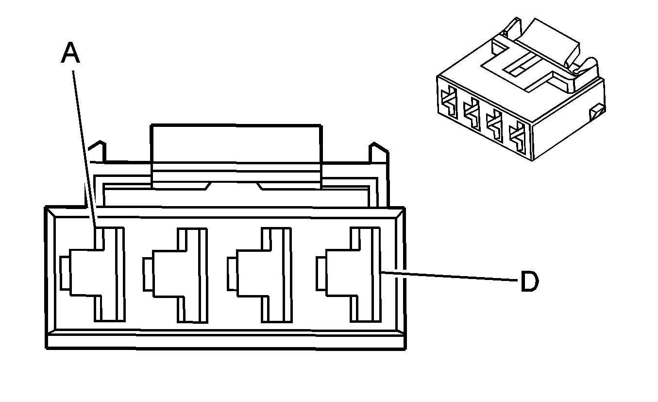
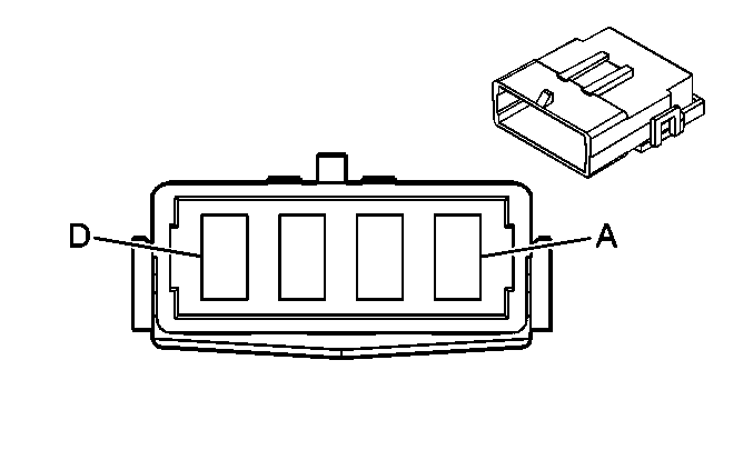
A | YE/BK | 2516 | Keypad Green LED Signal (UE1) | A | YE/BK | 2516 | Keypad Green LED Signal (UE1) | ||||||||
B | BN/WH | 2517 | Keypad RD LED Signal (UE1) | B | BN/WH | 2517 | Keypad RD LED Signal (UE1) | ||||||||
C | L-GN/BK | 2515 | Keypad Supply Voltage (UE1) | C | L-GN/BK | 2515 | Keypad Supply Voltage (UE1) | ||||||||
D | D-GN/WH | 2514 | Keypad Signal (UE1) | D | D-GN/WH | 2514 | Keypad Signal (UE1) | ||||||||
E-H | -- | -- | Not Used | E-H | -- | -- | Not Used | ||||||||
|
| ||||||||||||||
|---|---|---|---|---|---|---|---|---|---|---|---|---|---|---|---|
Connector Part Information |
| Connector Part Information |
| ||||||||||||
Pin | Wire Color | Circuit No. | Function | Pin | Wire Color | Circuit No. | Function | ||||||||
A | BK | 50 | Ground | A | BK | 50 | Ground | ||||||||
B | -- | -- | Not Used | B | -- | -- | Not Used | ||||||||
C | YE | 243 | Accessory Voltage | C | YE | 243 | Accessory Voltage | ||||||||
D | RD | 2 | Battery Positive Voltage | D | RD | 2 | Battery Positive Voltage | ||||||||
|
| ||||||||||||||
|---|---|---|---|---|---|---|---|---|---|---|---|---|---|---|---|
Connector Part Information |
| Connector Part Information |
| ||||||||||||
Pin | Wire Color | Circuit No. | Function | Pin | Wire Color | Circuit No. | Function | ||||||||
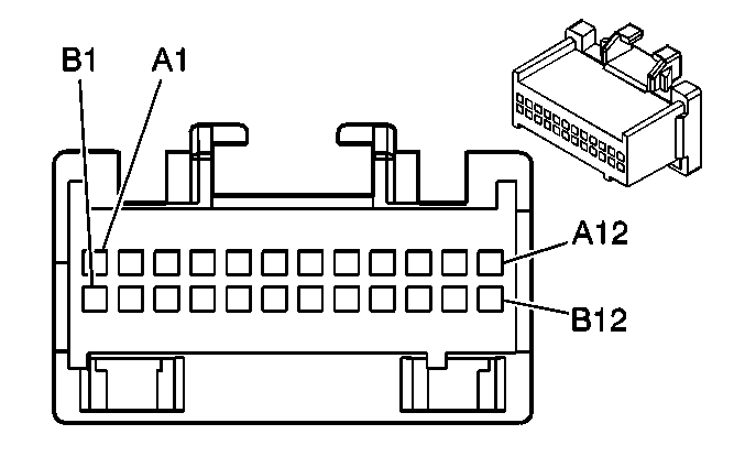
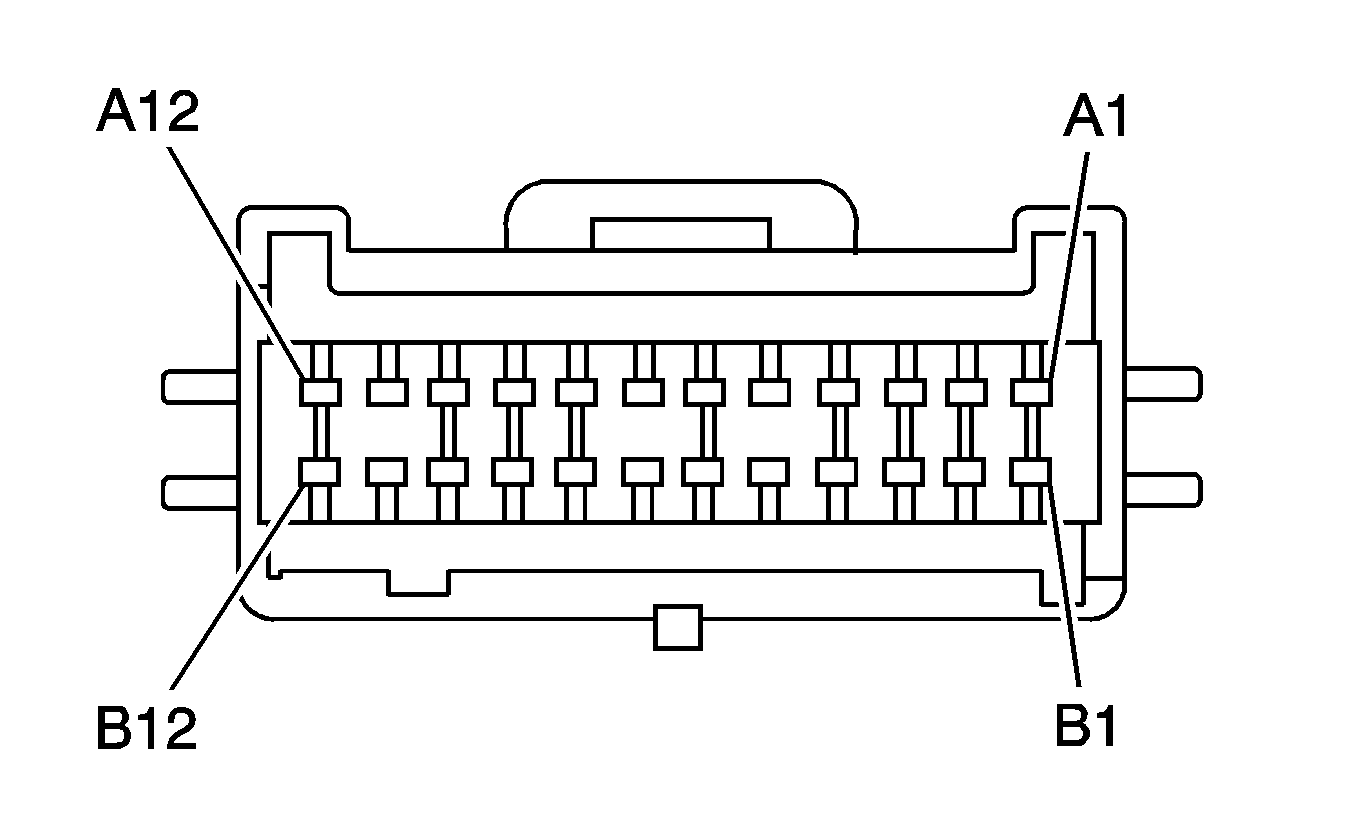
A1 | OG | 1044 | Class 2 Serial Data | A1 | OG | 1044 | Class 2 Serial Data | ||||||||
A2-A7 | -- | -- | Not Used | A2-A7 | -- | -- | Not Used | ||||||||
A8 | TN | 201 | Left Front Speaker Output (+) | A8 | TN | 201 | Left Front Speaker Output (+) | ||||||||
A9 | GY | 118 | Left Front Speaker Output (-) | A9 | GY | 118 | Left Front Speaker Output (-) | ||||||||
A10 | L-BU | 115 | Right Rear Speaker Output (-) | A10 | L-BU | 115 | Right Rear Speaker Output (-) | ||||||||
A11 | D-BU | 46 | Right Rear Speaker Output (+) | A11 | D-BU | 46 | Right Rear Speaker Output (+) | ||||||||
A12 | BK/WH | 1851 | Ground | A12 | BK/WH | 1851 | Ground | ||||||||
B1 | OG | 340 | Battery Positive Voltage | B1 | OG | 340 | Battery Positive Voltage | ||||||||
B2-B7 | -- | -- | Not Used | B2-B7 | -- | -- | Not Used | ||||||||
B8 | BN | 199 | Left Rear Speaker Output (+) | B8 | BN | 199 | Left Rear Speaker Output (+) | ||||||||
B9 | YE | 116 | Left Rear Speaker Output (-) | B9 | YE | 116 | Left Rear Speaker Output (-) | ||||||||
B10 | D-GN | 117 | Right Front Speaker Output (-) | B10 | D-GN | 117 | Right Front Speaker Output (-) | ||||||||
B11 | L-GN | 200 | Right Front Speaker Output (+) | B11 | L-GN | 200 | Right Front Speaker Output (+) | ||||||||
B12 | -- | -- | Not Used | B12 | -- | -- | Not Used | ||||||||
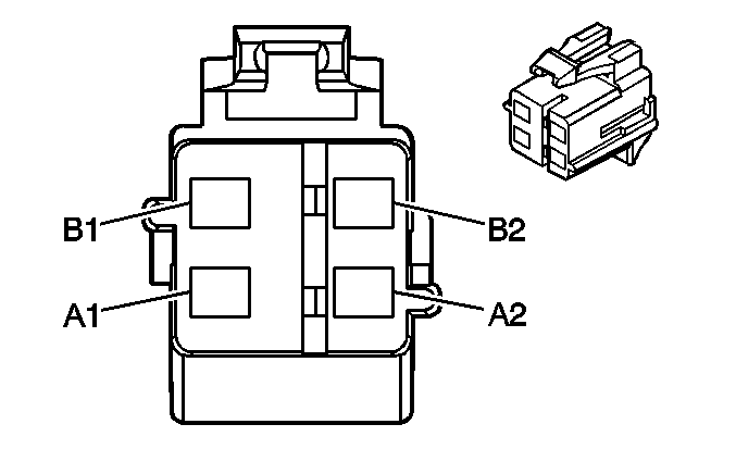
|
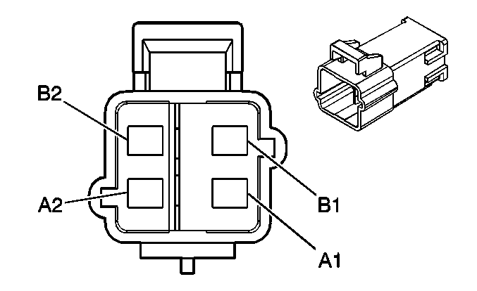
| ||||||||||||||
|---|---|---|---|---|---|---|---|---|---|---|---|---|---|---|---|
Connector Part Information |
| Connector Part Information |
| ||||||||||||
Pin | Wire Color | Circuit No. | Function | Pin | Wire Color | Circuit No. | Function | ||||||||
A1 | WH | 347 | Steering Wheel Module - High Control | A1 | TN | 3021 | Steering Wheel Module - Stage 1 - High Control | ||||||||
A2 | D-GN | 348 | Steering Wheel Module - Low Control | A2 | BN | 3020 | Steering Wheel Module - Stage 1 - Low Control | ||||||||
B1-B2 | -- | -- | Not Used | B1-B2 | -- | -- | Not Used | ||||||||

|

| ||||||||||||||
|---|---|---|---|---|---|---|---|---|---|---|---|---|---|---|---|
Connector Part Information |
| Connector Part Information |
| ||||||||||||
Pin | Wire Color | Circuit No. | Function | Pin | Wire Color | Circuit No. | Function | ||||||||
A1 | TN | 3021 | Steering Wheel Module - Stage 1 - High Control | A1 | TN | 3021 | Steering Wheel Module - Stage 1 - High Control | ||||||||
A2 | BN | 3020 | Steering Wheel Module - Stage 1 - Low Control | A2 | BN | 3020 | Steering Wheel Module - Stage 1 - Low Control | ||||||||
B1 | WH | 3023 | Steering Wheel Module - Stage 2 - High Control | B1 | WH | 3023 | Steering Wheel Module - Stage 2 - High Control | ||||||||
B2 | PK | 2022 | Steering Wheel Module - Stage 2 - Low Control | B2 | PK | 2022 | Steering Wheel Module - Stage 2 - Low Control | ||||||||

|

| ||||||||||||||
|---|---|---|---|---|---|---|---|---|---|---|---|---|---|---|---|
Connector Part Information |
| Connector Part Information |
| ||||||||||||
Pin | Wire Color | Circuit No. | Function | Pin | Wire Color | Circuit No. | Function | ||||||||
A1 | YE | 3025 | I/P Module - Stage 1 - High Control | A1 | YE | 3025 | I/P Module - Stage 1 - High Control | ||||||||
A2 | OG | 3024 | I/P Module - Stage 1 - Low Control | A2 | OG | 3024 | I/P Module - Stage 1 - Low Control | ||||||||
B1 | GY | 3027 | I/P Module - Stage 2 - High Control (w/Dual Stage) (AL0) | B1 | GY | 3027 | I/P Module - Stage 2 - High Control (w/Dual Stage) (AL0) | ||||||||
B2 | PU | 3026 | I/P Module - Stage 2 - Low Control (w/Dual Stage) (AL0) | B2 | PU | 3026 | I/P Module - Stage 2 - Low Control (w/Dual Stage) (AL0) | ||||||||
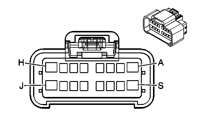
|
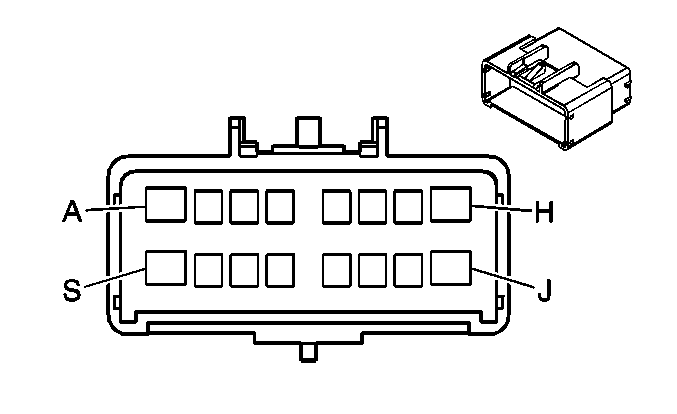
| ||||||||||||||
|---|---|---|---|---|---|---|---|---|---|---|---|---|---|---|---|
Connector Part Information |
| Connector Part Information |
| ||||||||||||
Pin | Wire Color | Circuit No. | Function | Pin | Wire Color | Circuit No. | Function | ||||||||
A | D-BU/WH | 2218 | Serial Communications Circuit | A | D-BU | 1128 | SDM Class 2 Serial Data | ||||||||
A | BN/WH | 1048 | SCM (Seat) Class 2 Serial Data (AG2) | ||||||||||||
B | YE | 116 | Left Rear Speaker Output (-) | B | YE | 116 | Left Rear Speaker Output (-) | ||||||||
C | BN | 199 | Left Rear Speaker Output (+) | C | BN | 199 | Left Rear Speaker Output (+) | ||||||||
D | L-BU | 115 | Right Rear Speaker Output (-) | D | L-BU | 115 | Right Rear Speaker Output (-) | ||||||||
E | D-BU | 46 | Right Rear Speaker Output (+) | E | D-BU | 46 | Right Rear Speaker Output (+) | ||||||||
F | -- | -- | Not Used | F | -- | -- | Not Used | ||||||||
G | YE | 354 | Discriminating Sensor - Signal | G | YE | 354 | Discriminating Sensor - Signal | ||||||||
H | GY | 349 | Discriminating Sensor - Left - Signal | H | GY | 349 | Discriminating Sensor - Left - Signal | ||||||||
J | YE | 1834 | Forward Discriminating Sensor Signal | J | YE | 1834 | Forward Discriminating Sensor Signal | ||||||||
K | PK | 353 | I/P Module Suppression Indicator Control (Except 10 Series and Crew Cab) | K | PK | 353 | I/P Module Suppression Indicator Control (Except 10 Series and Crew Cab) | ||||||||
L | TN/BK | 371 | I/P Module Suppression Indicator Control (Except 10 Series and Crew Cab) | L | TN/BK | 371 | I/P Module Suppression Indicator Control (Except 10 Series and Crew Cab) | ||||||||
M | D-GN | 1409 | Discriminating Sensor - Right - Signal | M | D-GN | 1409 | Discriminating Sensor - Right - Signal | ||||||||
N-S | -- | -- | Not Used | N-S | -- | -- | Not Used | ||||||||
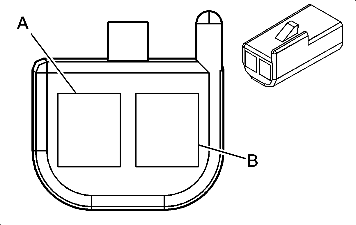
|
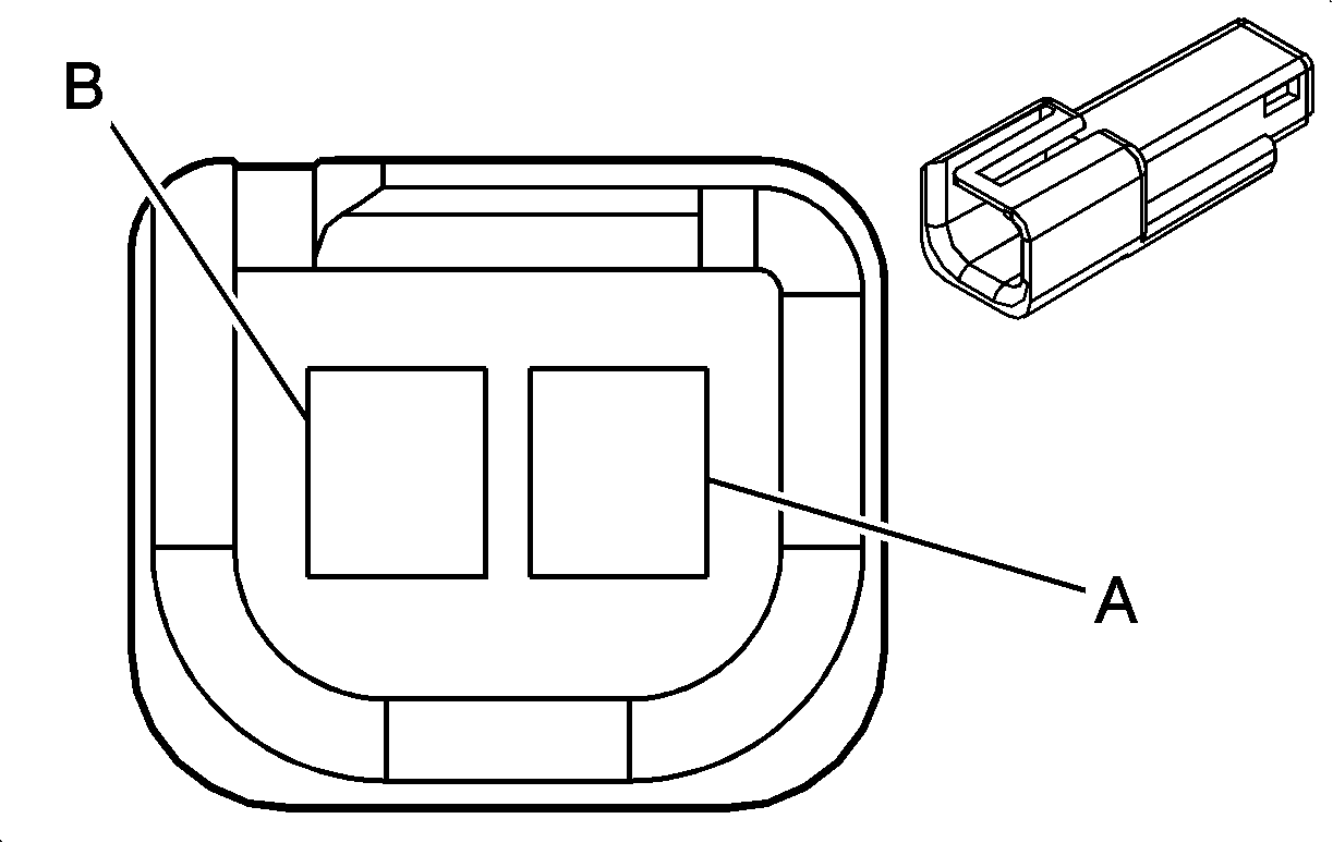
| ||||||||||||||
|---|---|---|---|---|---|---|---|---|---|---|---|---|---|---|---|
Connector Part Information |
| Connector Part Information |
| ||||||||||||
Pin | Wire Color | Circuit No. | Function | Pin | Wire Color | Circuit No. | Function | ||||||||
A | BARE | 514 | Ground | A | BARE | 514 | Ground | ||||||||
B | GY | 655 | Cellular Telephone Microphone Low Reference | B | GY | 655 | Cellular Telephone Microphone Low Reference | ||||||||
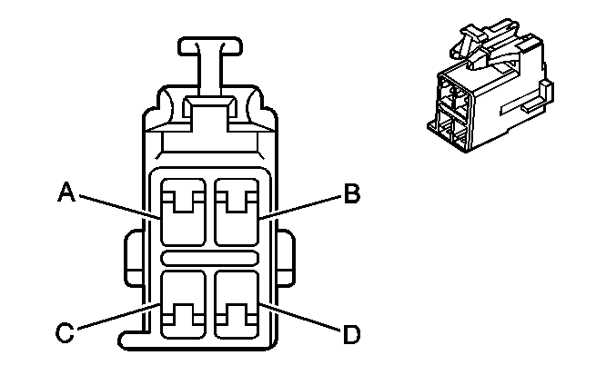
|
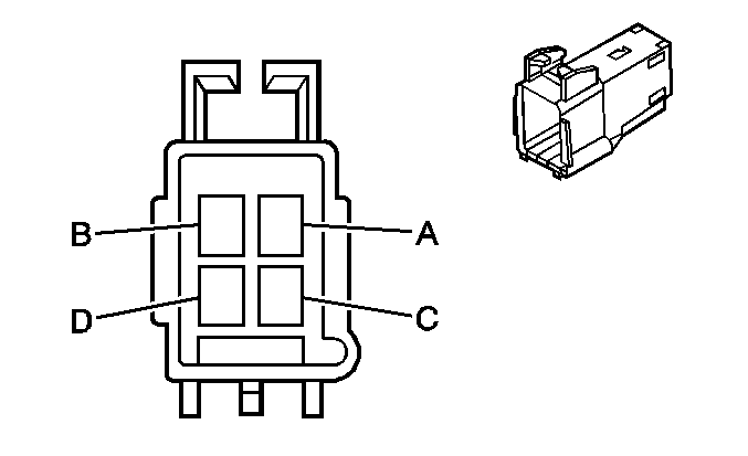
| ||||||||||||||
|---|---|---|---|---|---|---|---|---|---|---|---|---|---|---|---|
Connector Part Information |
| Connector Part Information |
| ||||||||||||
Pin | Wire Color | Circuit No. | Function | Pin | Wire Color | Circuit No. | Function | ||||||||
A | OG | 1040 | Battery Positive Voltage | A | OG | 1040 | Battery Positive Voltage | ||||||||
B | OG | 640 | Battery Positive Voltage | B | OG | 640 | Battery Positive Voltage | ||||||||
C | BK | 1050 | Ground | C | BK | 1050 | Ground | ||||||||
D | -- | -- | Not Used | D | -- | -- | Not Used | ||||||||
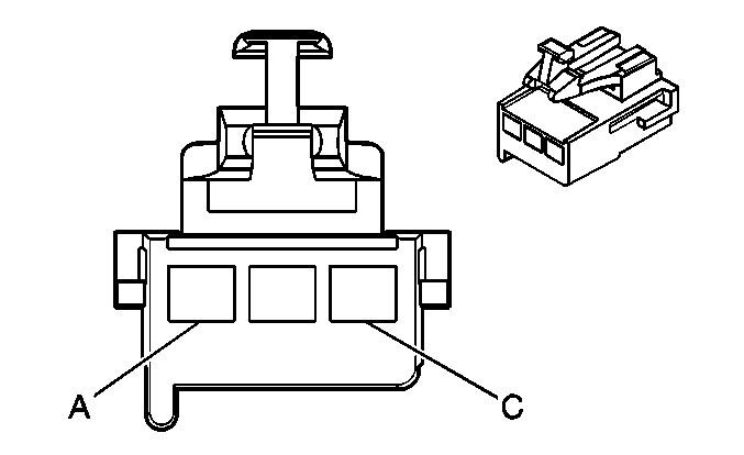
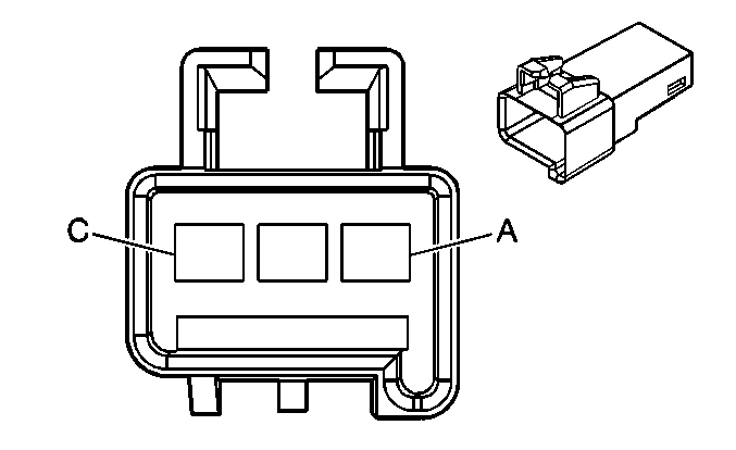
|
| ||||||||||||||
|---|---|---|---|---|---|---|---|---|---|---|---|---|---|---|---|
Connector Part Information |
| Connector Part Information |
| ||||||||||||
Pin | Wire Color | Circuit No. | Function | Pin | Wire Color | Circuit No. | Function | ||||||||
A | OG | 640 | Battery Positive Voltage | A | OG | 640 | Battery Positive Voltage | ||||||||
B | -- | -- | Not Used | B | -- | -- | Not Used | ||||||||
C | BK | 1050 | Ground | C | BK | 1050 | Ground | ||||||||
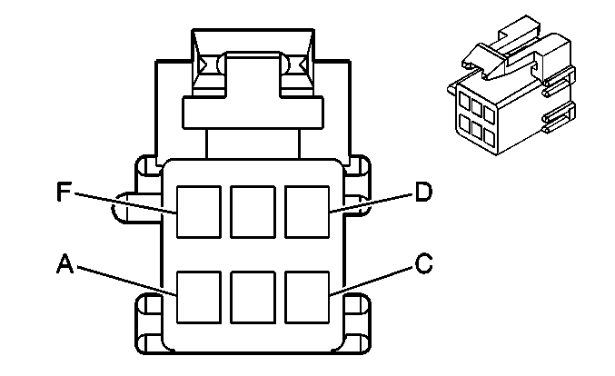
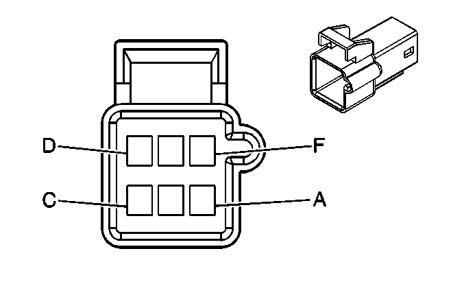
|
| ||||||||||||||
|---|---|---|---|---|---|---|---|---|---|---|---|---|---|---|---|
Connector Part Information |
| Connector Part Information |
| ||||||||||||
Pin | Wire Color | Circuit No. | Function | Pin | Wire Color | Circuit No. | Function | ||||||||
A | -- | -- | Not Used | A | -- | -- | Not Used | ||||||||
B | BK | 1050 | Ground | B | BK | 1050 | Ground | ||||||||
C | TN/WH | 1384 | Selective Ride Control Switch Signal | C | TN/WH | 1384 | Selective Ride Control Switch Signal | ||||||||
D | PU/WH | 1382 | LED Dimming Signal/LED Dimming Supply | D | PU/WH | 1382 | LED Dimming Signal/LED Dimming Supply | ||||||||
E | BN/WH | 230 | Instrument Panel Lamps Dimming Control | E | BN/WH | 230 | Instrument Panel Lamps Dimming Control | ||||||||
F | PK | 739 | Ignition 1 Voltage | F | PK | 739 | Ignition 1 Voltage | ||||||||

|

| ||||||||||||||
|---|---|---|---|---|---|---|---|---|---|---|---|---|---|---|---|
Connector Part Information |
| Connector Part Information |
| ||||||||||||
Pin | Wire Color | Circuit No. | Function | Pin | Wire Color | Circuit No. | Function | ||||||||
A | -- | -- | Not Used | A | -- | -- | Not Used | ||||||||
B | BK | 1050 | Ground | B | BK | 1050 | Ground | ||||||||
C | WH | 111 | Hazard Switch Signal | C | WH | 111 | Hazard Switch Signal | ||||||||
D | PU/WH | 1382 | LED Dimming Signal/LED Dimming Supply | D | PU/WH | 1382 | LED Dimming Signal/LED Dimming Supply | ||||||||
E | BN/WH | 230 | Instrument Panel Lamps Dimming Control | E | BN/WH | 230 | Instrument Panel Lamps Dimming Control | ||||||||
F | OG | 4540 | Battery Positive Voltage | F | OG | 4540 | Battery Positive Voltage | ||||||||
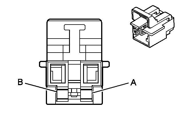
|
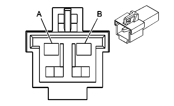
| ||||||||||||||
|---|---|---|---|---|---|---|---|---|---|---|---|---|---|---|---|
Connector Part Information |
| Connector Part Information |
| ||||||||||||
Pin | Wire Color | Circuit No. | Function | Pin | Wire Color | Circuit No. | Function | ||||||||
A | WH | 347 | Steering Wheel Module - High Control | A | BN | 347 | Steering Wheel Module - High Control | ||||||||
B | D-GN | 348 | Steering Wheel Module - Low Control | B | BK | 348 | Steering Wheel Module - Low Control | ||||||||

|

| ||||||||||||||
|---|---|---|---|---|---|---|---|---|---|---|---|---|---|---|---|
Connector Part Information |
| Connector Part Information |
| ||||||||||||
Pin | Wire Color | Circuit No. | Function | Pin | Wire Color | Circuit No. | Function | ||||||||
A1 | TN | 3021 | Steering Wheel Module - Stage 1 - High Control | A1 | TN | 3021 | Steering Wheel Module - Stage 1 - High Control | ||||||||
A2 | BN | 3020 | Steering Wheel Module - Stage 1 - Low Control | A2 | BN | 3020 | Steering Wheel Module - Stage 1 - Low Control | ||||||||
B1 | WH | 3023 | Steering Wheel Module - Stage 2 - High Control | B1 | WH | 3023 | Steering Wheel Module - Stage 2 - High Control | ||||||||
B2 | PK | 3022 | Steering Wheel Module - Stage 2 - Low Control | B2 | PK | 3022 | Steering Wheel Module - Stage 2 - Low Control | ||||||||

|

| ||||||||||||||
|---|---|---|---|---|---|---|---|---|---|---|---|---|---|---|---|
Connector Part Information |
| Connector Part Information |
| ||||||||||||
Pin | Wire Color | Circuit No. | Function | Pin | Wire Color | Circuit No. | Function | ||||||||
A | YE | 1327 | DIC Fuel Signal | A | YE | 1327 | DIC Fuel Signal | ||||||||
B | D-BU | 894 | DIC Toggle Switch Signal | B | D-BU | 894 | DIC Toggle Switch Signal | ||||||||
C | PU | 1358 | DIC Switch Signal | C | D-GN | 1358 | DIC Switch Signal | ||||||||
D | OG/BK | 1816 | DIC Set/Reset Switch Signal | D | OG | 1816 | DIC Set/Reset Switch Signal | ||||||||
E | PK | 1796 | Steering Wheel Controls Signal | E | WH | 2283 | 12-Volt Reference | ||||||||
F | BN/WH | 230 | Instrument Panel Lamps Dimming Control | F | BN | 230 | Instrument Panel Lamps Dimming Control | ||||||||
G | L-GN | 1011 | Remote Radio Control Signal | G | L-GN | 1011 | Remote Radio Control Signal | ||||||||
G | L-GN | 1011 | Remote Radio Control Signal | ||||||||||||
H | BK | 1851 | Ground | H | BK | 2250 | Ground | ||||||||

|

| ||||||||||||||
|---|---|---|---|---|---|---|---|---|---|---|---|---|---|---|---|
Connector Part Information |
| Connector Part Information |
| ||||||||||||
Pin | Wire Color | Circuit No. | Function | Pin | Wire Color | Circuit No. | Function | ||||||||
A | OG | 1440 | Battery Positive Voltage (AG1) | A | OG | 1440 | Battery Positive Voltage (AG1) | ||||||||
B | PK | 2480 | Driver Heated Seat Cushion Element Control (KA1) | B | PK/BK | 2480 | Driver Heated Seat Cushion Element Control (KA1) | ||||||||
C | -- | -- | Not Used | C | -- | -- | Not Used | ||||||||
D | BN/WH | 1048 | Class 2 Serial Data (AN3) | D | BN/WH | 1048 | Class 2 Serial Data (AN3) | ||||||||
E | BK/WH | 238 | Seat Belt Switch - Left | E | BK/WH | 238 | Seat Belt Switch - Left | ||||||||
F | L-GN | 5055 | Seat Position Switch - Left - Signal (AL0) | F | L-GN | 5055 | Seat Position Switch - Left - Signal (AL0) | ||||||||
G | L-BU | 2433 | Driver Heated Seat Back Element Control (KA1) | G | L-BU | 2433 | Driver Heated Seat Back Element Control (KA1) | ||||||||
H | D-BU | 2479 | Driver Heated Seat Element Supply Voltage (KA1) | H | D-BU | 2479 | Driver Heated Seat Element Supply Voltage (KA1) | ||||||||
J | D-BU | 1363 | Seat Belt Switch - Left - Low Reference | J | YE | 234 | Seat Belt Indicator Control | ||||||||
D-BU | 1363 | Seat Belt Switch - Right - Low Reference (AL0) | YE | 234 | Seat Belt Indicator Control (AL0) | ||||||||||
K | D-BU | 5475 | Driver Heated Seat Back Temperature Signal (KA1) | K | D-BU/YE | 5475 | Driver Heated Seat Back Temperature Signal (KA1) | ||||||||
L | L-BU | 2751 | Low Reference | L | L-BU | 2751 | Low Reference | ||||||||
M-N | -- | -- | Not Used | M-N | -- | -- | Not Used | ||||||||
P | WH | 1985 | Not Used (5-Volt Reference) | P | -- | -- | Not Used | ||||||||
R | -- | -- | Not Used | R | -- | -- | Not Used | ||||||||
S | BK | 1150 | Ground | S | BK | 1150 | Ground | ||||||||
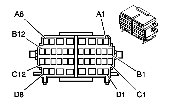
|
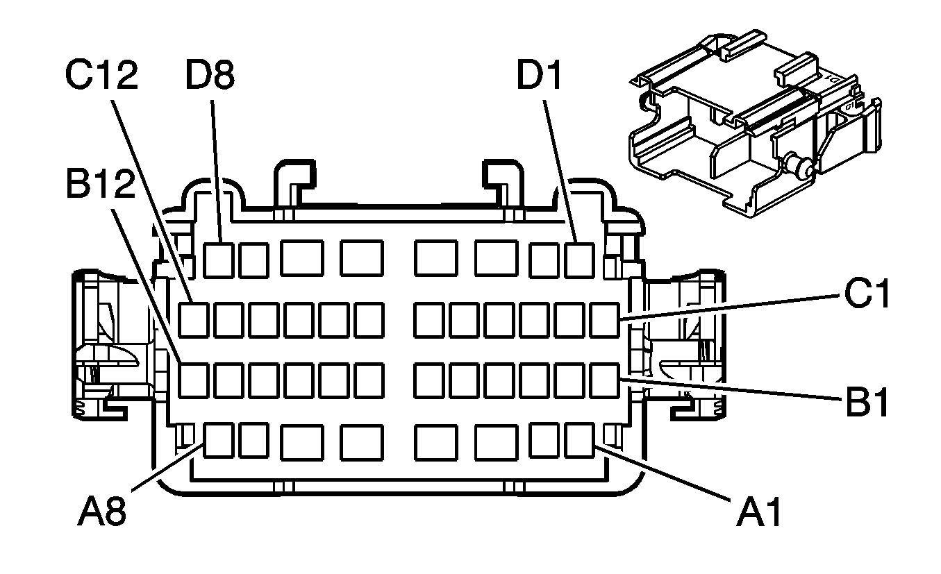
| ||||||||||||||
|---|---|---|---|---|---|---|---|---|---|---|---|---|---|---|---|
Connector Part Information |
| Connector Part Information |
| ||||||||||||
Pin | Wire Color | Circuit No. | Function | Pin | Wire Color | Circuit No. | Function | ||||||||
A1 | BARE | 2011 | Drain Wire (UQ7) | A1 | BARE | 2011 | Drain Wire (UQ7) | ||||||||
A2-A3 | -- | -- | Not Used | A2-A3 | -- | -- | Not Used | ||||||||
A4 | OG | 1040 | Battery Positive Voltage | A4 | OG | 1040 | Battery Positive Voltage | ||||||||
A5 | OG | 3740 | Battery Positive Voltage | A5 | OG | 3740 | Battery Positive Voltage | ||||||||
A6-A8 | -- | -- | Not Used | A6-A8 | -- | -- | Not Used | ||||||||
B1-B2 | -- | -- | Not Used | B1-B2 | -- | -- | Not Used | ||||||||
B3 | L-BU | 2288 | Class 2 Serial Data | B3 | L-BU | 2288 | Class 2 Serial Data | ||||||||
B4 | GY/BK | 2334 | Radio Mute | B4 | GY/BK | 2334 | Radio Mute | ||||||||
B5 | -- | -- | Not Used | B5 | -- | -- | Not Used | ||||||||
B6 | PK | 314 | Radio On Signal | B6 | PK | 314 | Radio On Signal | ||||||||
B7 | -- | -- | Not Used | B7 | -- | -- | Not Used | ||||||||
B8 | BK | 1050 | Ground | B8 | BK | 1050 | Ground | ||||||||
B9 | TN | 201 | Left Front Speaker Output (+) | B9 | TN | 201 | Left Front Speaker Output (+) | ||||||||
B10 | -- | -- | Not Used | B10 | -- | -- | Not Used | ||||||||
B11 | GY | 118 | Left Front Speaker Output (-) | B11 | GY | 118 | Left Front Speaker Output (-) | ||||||||
B12 | PU | 493 | Rear Seat Audio Enable Signal | B12 | PU | 493 | Rear Seat Audio Enable Signal | ||||||||
C1 | BARE | 2099 | Drain Wire | C1 | BARE | 2099 | Drain Wire | ||||||||
C2 | TN | 511 | Left Front Low Level Audio Signal (+) | C2 | TN | 511 | Left Front Low Level Audio Signal (+) | ||||||||
C3 | D-GN | 1947 | Left Front Low Level Audio Signal (-) | C3 | D-GN | 1947 | Left Front Low Level Audio Signal (-) | ||||||||
C4 | L-GN | 512 | Right Front Low Level Audio Signal (+) | C4 | L-GN | 512 | Right Front Low Level Audio Signal (+) | ||||||||
C5 | OG | 640 | Battery Positive Voltage | C5 | OG | 640 | Battery Positive Voltage | ||||||||
C6 | BK | 1946 | Right Rear Low Level Audio Signal (-) | C6 | BK | 1946 | Right Rear Low Level Audio Signal (-) | ||||||||
C7 | OG/BK | 1546 | Front Low Level Audio Signal (-) | C7 | OG/BK | 1546 | Front Low Level Audio Signal (-) | ||||||||
C8 | BN | 599 | Left Rear Low Level Audio Signal (+) | C8 | BN | 599 | Left Rear Low Level Audio Signal (+) | ||||||||
C9 | D-GN/WH | 1547 | Rear Low Level Audio Signal (-) | C9 | D-GN/WH | 1547 | Rear Low Level Audio Signal (-) | ||||||||
C10 | BN | 199 | Left Rear Speaker Output (+) | C10 | BN | 199 | Left Rear Speaker Output (+) | ||||||||
C11 | D-BU | 546 | Right Rear Low Level Audio Signal (+) | C11 | D-BU | 546 | Right Rear Low Level Audio Signal (+) | ||||||||
C12 | L-GN | 200 | Right Front Speaker Output (+) | C12 | L-GN | 200 | Right Front Speaker Output (+) | ||||||||
D1 | D-GN | 117 | Right Front Speaker Output (-) | D1 | D-GN | 117 | Right Front Speaker Output (-) | ||||||||
D2 | YE | 116 | Left Rear Speaker Output (-) | D2 | L-GN | 116 | Left Rear Speaker Output (-) | ||||||||
D3-D4 | -- | -- | Not Used | D3-D4 | -- | -- | Not Used | ||||||||
D5 | BK/WH | 1851 | Ground | D5 | BK/WH | 1851 | Ground | ||||||||
D6 | OG | 340 | Battery Positive Voltage | D6 | OG | 340 | Battery Positive Voltage | ||||||||
D7 | D-BU | 46 | Right Rear Speaker Output (+) | D7 | D-BU | 46 | Right Rear Speaker Output (+) | ||||||||
D8 | L-BU | 115 | Right Rear Speaker Output (-) | D8 | L-BU | 115 | Right Rear Speaker Output (-) | ||||||||

|

| ||||||||||||||
|---|---|---|---|---|---|---|---|---|---|---|---|---|---|---|---|
Connector Part Information |
| Connector Part Information |
| ||||||||||||
Pin | Wire Color | Circuit No. | Function | Pin | Wire Color | Circuit No. | Function | ||||||||
A1 | BN/WH | 230 | Instrument Panel Lamps Dimming Control | A1 | BN/WH | 230 | Instrument Panel Lamps Dimming Control | ||||||||
A2 | -- | -- | Not Used | A2 | -- | -- | Not Used | ||||||||
A3 | BN/WH | 230 | Instrument Panel Lamps Dimming Control (Z75) | A3 | BN/WH | 230 | Instrument Panel Lamps Dimming Control (Z75) | ||||||||
A4 | OG | 1040 | Battery Positive Voltage | A4 | OG | 1040 | Battery Positive Voltage | ||||||||
A5 | OG | 3740 | Battery Positive Voltage | A5 | OG | 3740 | Battery Positive Voltage | ||||||||
A6 | OG | 3240 | Battery Positive Voltage | A6 | OG | 3240 | Battery Positive Voltage | ||||||||
A7 | D-GN/WH | 368 | Right Audio Signal (+) | A7 | D-GN/WH | 368 | Right Audio Signal (+) | ||||||||
A8 | BN/WH | 367 | Left Audio Signal (+) | A8 | BN/WH | 367 | Left Audio Signal (+) | ||||||||
B1 | BK/WH | 372 | Audio Common | B1 | BK/WH | 372 | Audio Common | ||||||||
B2 | -- | -- | Not Used | B2 | -- | -- | Not Used | ||||||||
B3 | L-BU | 2288 | Class 2 Serial Data (UK6) | B3 | L-BU | 2288 | Class 2 Serial Data (UK6) | ||||||||
B4 | -- | -- | Not Used | B4 | -- | -- | Not Used | ||||||||
B5 | TN | 5072 | Remote Playback Device Class 2 Serial Data | B5 | TN | 5072 | Remote Playback Device Class 2 Serial Data | ||||||||
B6 | -- | -- | Not Used | B6 | -- | -- | Not Used | ||||||||
B7 | D-BU | 2272 | Amplifier Class 2 Serial Data | B7 | D-BU | 2272 | Amplifier Class 2 Serial Data | ||||||||
B8 | BK | 1050 | Ground | B8 | BK | 1050 | Ground | ||||||||
B9 | TN | 201 | Left Front Speaker Output (+) | B9 | TN | 201 | Left Front Speaker Output (+) | ||||||||
B10 | BARE | 1573 | Drain Wire | B10 | BARE | 1573 | Drain Wire | ||||||||
B11 | GY | 118 | Left Front Speaker Output (-) | B11 | GY | 118 | Left Front Speaker Output (-) | ||||||||
B12 | -- | -- | Not Used | B12 | -- | -- | Not Used | ||||||||
C1 | -- | -- | Not Used | C1 | -- | -- | Not Used | ||||||||
C2 | TN | 511 | Left Front Low Level Audio Signal (+) | C2 | TN | 511 | Left Front Low Level Audio Signal (+) | ||||||||
C3 | D-GN | 1947 | Left Front Low Level Audio Signal (-) | C3 | D-GN | 1947 | Left Front Low Level Audio Signal (-) | ||||||||
C4 | L-GN | 512 | Right Front Low Level Audio Signal (+) | C4 | L-GN | 512 | Right Front Low Level Audio Signal (+) | ||||||||
C5 | OG | 640 | Battery Positive Voltage | C5 | OG | 640 | Battery Positive Voltage | ||||||||
C6 | BK | 1946 | Right Rear Low Level Audio Signal (-) | C6 | BK | 1946 | Right Rear Low Level Audio Signal (-) | ||||||||
C7 | OG/BK | 1546 | Front Low Level Audio Signal (-) | C7 | OG/BK | 1546 | Front Low Level Audio Signal (-) | ||||||||
C8 | BN | 599 | Left Rear Low Level Audio Signal (+) | C8 | BN | 599 | Left Rear Low Level Audio Signal (+) | ||||||||
C9 | D-GN/WH | 1547 | Rear Low Level Audio Signal (-) | C9 | D-GN/WH | 1547 | Rear Low Level Audio Signal (-) | ||||||||
C10 | BN | 199 | Left Rear Speaker Output (+) | C10 | BN | 199 | Left Rear Speaker Output (+) | ||||||||
C11 | D-BU | 546 | Right Rear Low Level Audio Signal (+) | C11 | D-BU | 546 | Right Rear Low Level Audio Signal (+) | ||||||||
C12 | L-GN | 200 | Right Front Speaker Output (+) | C12 | L-GN | 200 | Right Front Speaker Output (+) | ||||||||
D1 | D-GN | 117 | Right Front Speaker Output (-) | D1 | D-GN | 117 | Right Front Speaker Output (-) | ||||||||
D2 | YE | 116 | Left Rear Speaker Output (-) | D2 | L-GN | 116 | Left Rear Speaker Output (-) | ||||||||
D3 | BN/WH | 230 | Instrument Panel Lamps Dimming Control | D3 | BN/WH | 230 | Instrument Panel Lamps Dimming Control | ||||||||
D4 | BARE | 2011 | Drain Wire | D4 | BARE | 2011 | Drain Wire | ||||||||
D5 | BK/WH | 1851 | Ground | D5 | BK/WH | 1851 | Ground | ||||||||
D6 | OG | 340 | Battery Positive Voltage (UK6) | D6 | OG | 340 | Battery Positive Voltage (UK6) | ||||||||
D7 | D-BU | 46 | Right Rear Speaker Output (+) | D7 | D-BU | 46 | Right Rear Speaker Output (+) | ||||||||
D8 | L-BU | 115 | Right Rear Speaker Output (-) | D8 | L-BU | 115 | Right Rear Speaker Output (-) | ||||||||
|
| ||||||||||||||
|---|---|---|---|---|---|---|---|---|---|---|---|---|---|---|---|
Connector Part Information |
| Connector Part Information |
| ||||||||||||
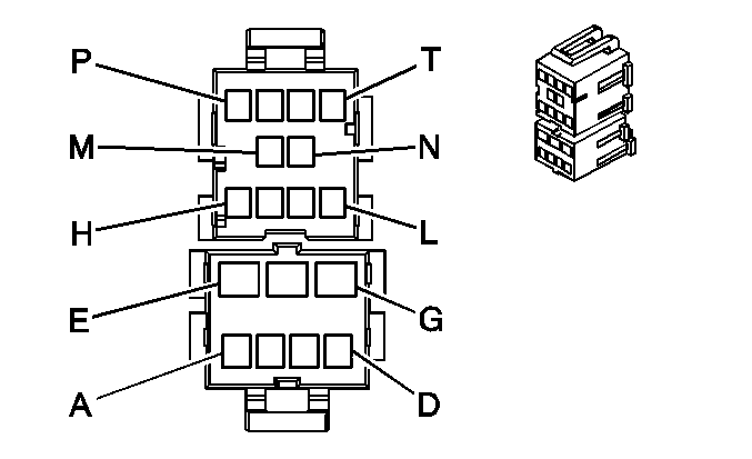
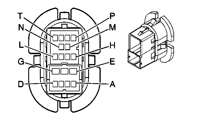
Pin | Wire Color | Circuit No. | Function | Pin | Wire Color | Circuit No. | Function | ||||||||
A | WH | 1185 | Power Window Relay Left Rear Up Control (YE9) | A | WH | 1185 | Power Window Relay Left Rear Up Control (YE9) | ||||||||
B | YE | 1187 | Power Window Relay Left Rear Down Control (YE9) | B | YE | 1187 | Power Window Relay Left Rear Down Control (YE9) | ||||||||
C | L-BU | 2265 | Power Window Lockout Left Rear Control (YE9) | C | L-BU | 2265 | Power Window Lockout Left Rear Control (YE9) | ||||||||
D | -- | -- | Not Used | D | -- | -- | Not Used | ||||||||
E | BN/WH | 230 | Instrument Panel Lamps Dimming Control (YE9) | E | BN/WH | 230 | Instrument Panel Lamps Dimming Control (YE9) | ||||||||
F | BK | 1150 | Ground (YE9) | F | BK | 1150 | Ground (YE9) | ||||||||
G | OG | 1240 | Battery Positive Voltage (YE9) | G | OG | 1240 | Battery Positive Voltage (YE9) | ||||||||
H | L-BU/BK | 747 | Left Rear Door Ajar Switch Signal | H | L-BU/BK | 747 | Left Rear Door Ajar Switch Signal | ||||||||
J | -- | -- | Not Used | J | -- | -- | Not Used | ||||||||
K | YE | 116 | Left Rear Speaker Output (-) | K | YE | 116 | Left Rear Speaker Output (-) | ||||||||
L | BN | 199 | Left Rear Speaker Output (+) | L | BN | 199 | Left Rear Speaker Output (+) | ||||||||
M | BK | 1150 | Ground | M | BK | 1150 | Ground | ||||||||
N | TN | 294 | Door Lock Actuator Unlock Control | N | TN | 294 | Door Lock Actuator Unlock Control | ||||||||
P | GY | 295 | Door Lock Actuator Lock Control | P | GY | 295 | Door Lock Actuator Lock Control | ||||||||
R-T | -- | -- | Not Used | R-T | -- | -- | Not Used | ||||||||
|
| ||||||||||||||
|---|---|---|---|---|---|---|---|---|---|---|---|---|---|---|---|
Connector Part Information |
| Connector Part Information |
| ||||||||||||
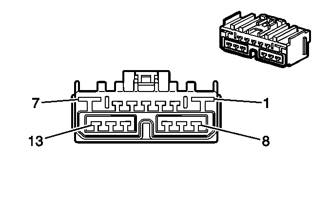
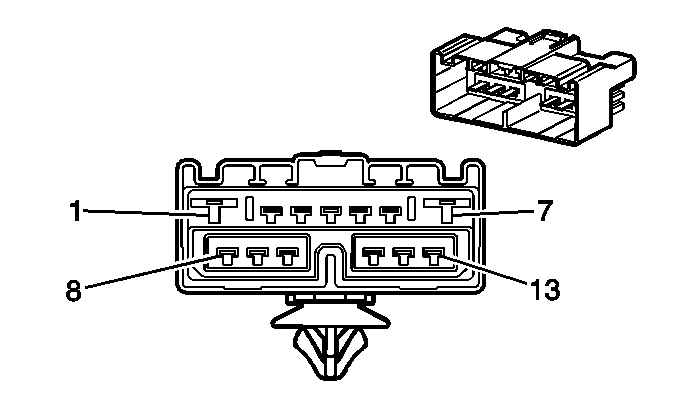
Pin | Wire Color | Wire Color | Function | Pin | Wire Color | Circuit No. | Function | ||||||||
1 | BK | 1150 | Ground | 1 | BK | 1150 | Ground | ||||||||
2 | D-BU | 611 | Drivers Seat Lumbar Motor Forward Control | 2 | D-BU | 611 | Drivers Seat Lumbar Motor Forward Control | ||||||||
3-5 | -- | -- | Not Used | 3-5 | -- | -- | Not Used | ||||||||
6 | D-BU | 2479 | Passenger Heated Seat Element Supply Voltage(KA1) | 6 | D-BU | 2479 | Passenger Heated Seat Element Supply Voltage (KA1) | ||||||||
D-BU | 2479 | Passenger Heated Seat Element Supply Voltage (KA1) | |||||||||||||
7 | OG | 1440 | Battery Positive Voltage | 7 | OG | 1440 | Battery Positive Voltage | ||||||||
8 | PU | 1258 | Driver Seat Torso Bolster Out Control | 8 | PU | 1258 | Driver Seat Torso Bolster Out Control | ||||||||
9 | YE | 1257 | Driver Seat Torso Bolster In Control | 9 | YE | 1257 | Driver Head Rest Motor Up Control | ||||||||
10 | -- | -- | Not Used | 10 | -- | -- | Not Used | ||||||||
11 | PK | 610 | Driver Seat Lumbar Motor Rearward Control | 11 | PK | 610 | Driver Seat Lumbar Motor Rearward Control | ||||||||
12 | PK/BK | 2480 | Passenger Heated Seat Cushion Element Control (KA1) | 12 | PK/BK | 2480 | Passenger Heated Seat Cushion Element Control (KA1) | ||||||||
13 | L-BU | 2433 | Passenger Heated Seat Back Element Control (KA1) | 13 | L-BU | 2433 | Passenger Heated Seat Back Element Control (KA1) | ||||||||
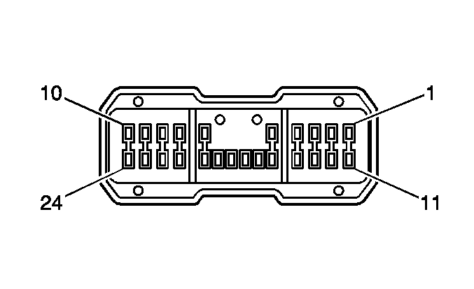
|
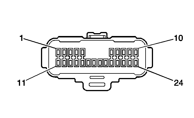
| ||||||||||||||
|---|---|---|---|---|---|---|---|---|---|---|---|---|---|---|---|
Connector Part Information |
| Connector Part Information |
| ||||||||||||
Pin | Wire Color | Circuit No. | Function | Pin | Wire Color | Circuit No. | Function | ||||||||
1 | WH | 940 | 12-Volt Reference | 1 | WH | 940 | 12-Volt Reference | ||||||||
2 | L-BU | 2751 | Low Reference | 2 | L-BU | 2751 | Low Reference | ||||||||
3 | YE/BK | 1063 | Driver Seat Lumbar Horizontal Position Sensor Signal | 3 | YE/BK | 1063 | Driver Seat Lumbar Horizontal Position Sensor Signal | ||||||||
4 | PU | 5700 | Drivers Seat Torso Bolster Position Sensor Signal | 4 | PU | 5700 | Drivers Seat Torso Bolster Position Sensor Signal | ||||||||
5 | -- | -- | Not Used | 5 | -- | -- | Not Used | ||||||||
6 | BN/WH | 718 | Low Reference | 6 | BN/WH | 718 | Low Reference | ||||||||
7 | OG | 1540 | Battery Positive Voltage | 7 | OG | 1540 | Battery Positive Voltage | ||||||||
8 | BN/WH | 1048 | Class 2 Serial Data | 8 | BN/WH | 1048 | Class 2 Serial Data | ||||||||
9 | D-GN | 1518 | Power Seat Front Vertical Up Switch Signal | 9 | D-GN | 1518 | Power Seat Front Vertical Up Switch Signal | ||||||||
10 | D-BU | 1520 | Power Seat Front Vertical Down Switch Signal | 10 | D-BU | 1520 | Power Seat Front Vertical Down Switch Signal | ||||||||
11 | GY/BK | 1269 | Power Seat Recline Forward Switch Signal | 11 | GY/BK | 1269 | Power Seat Recline Forward Switch Signal | ||||||||
12 | D-GN/WH | 1270 | Power Seat Recline Rearward Switch Signal | 12 | D-GN/WH | 1270 | Power Seat Recline Rearward Switch Signal | ||||||||
13 | L-GN | 1523 | Power Seat Horizontal Rearward Switch Signal | 13 | L-GN | 1523 | Power Seat Horizontal Rearward Switch Signal | ||||||||
14 | TN/BK | 1522 | Power Seat Horizontal Forward Switch Signal | 14 | TN | 1522 | Power Seat Horizontal Forward Switch Signal | ||||||||
15 | YE | 2407 | Driver Seat Lumbar Motor Forward Switch Signal | 15 | YE | 2407 | Driver Seat Lumbar Motor Forward Switch Signal | ||||||||
16 | TN | 2408 | Driver Seat Lumbar Rearward Control | 16 | TN | 2408 | Driver Seat Lumbar Rearward Control | ||||||||
17-18 | -- | -- | Not Used | 17-18 | -- | -- | Not Used | ||||||||
19 | L-BU | 1521 | Power Seat Rear Vertical Down Switch Signal | 19 | L-BU | 1521 | Power Seat Rear Vertical Down Switch Signal | ||||||||
20 | YE | 1519 | Power Seat Rear Vertical Up Switch Signal | 20 | YE | 1519 | Power Seat Rear Vertical Up Switch Signal | ||||||||
21 | WH/RD | 5701 | Drivers Seat Torso Bolster In Switch Signal | 21 | WH/RD | 5701 | Drivers Seat Torso Bolster In Switch Signal | ||||||||
22 | GY/RD | 5702 | Drivers Seat Torso Bolster Out Switch Signal | 22 | GY/RD | 5702 | Drivers Seat Torso Bolster Out Switch Signal | ||||||||
23 | D-BU/WH | 5475 | Front Passenger Heated Seat Back Temperature Signal (KA1) | 23 | D-BU/YE | 5475 | Front Passenger Heated Seat Back Temperature Signal (KA1) | ||||||||
24 | WH | 1985 | 5-Volt Reference | 24 | WH | 1985 | 5-Volt Reference | ||||||||
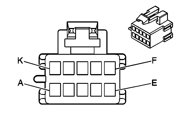
|
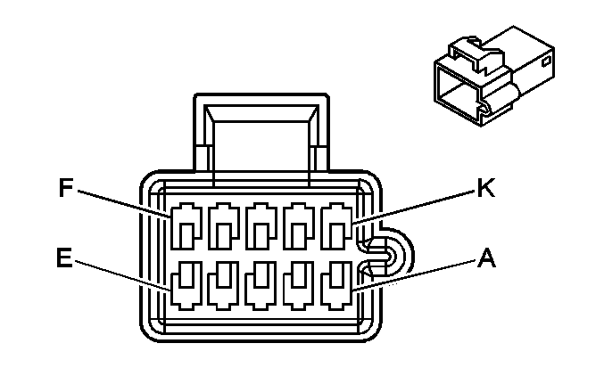
| ||||||||||||||
|---|---|---|---|---|---|---|---|---|---|---|---|---|---|---|---|
Connector Part Information |
| Connector Part Information |
| ||||||||||||
Pin | Wire Color | Circuit No. | Function | Pin | Wire Color | Circuit No. | Function | ||||||||
A | D-BU | 569 | Horizontal Seat Motor Position Sensor Signal | A | D-GN | 569 | Horizontal Seat Motor Position Sensor Signal | ||||||||
B | RD | 940 | 12-Volt Reference | B | WH | 940 | 12-Volt Reference | ||||||||
C | BK | 718 | Low Reference | C | BN/WH | 718 | Low Reference | ||||||||
D | D-BU | 557 | Front Vertical Seat Motor Position Sensor Signal | D | BN/WH | 557 | Front Vertical Seat Motor Position Sensor Signal | ||||||||
E | RD | 940 | 12-Volt Reference | E | WH | 940 | 12-Volt Reference | ||||||||
F | BK | 718 | Low Reference | F | BN/WH | 718 | Low Reference | ||||||||
G | D-BU | 568 | Rear Vertical Seat Motor Position Sensor Signal | G | TN | 568 | Rear Vertical Seat Motor Position Sensor Signal | ||||||||
H | RD | 940 | 12-Volt Reference | H | WH | 940 | 12-Volt Reference | ||||||||
J | BK | 718 | Low Reference | J | BN/WH | 718 | Low Reference | ||||||||
K | -- | -- | Not Used | K | -- | -- | Not Used | ||||||||
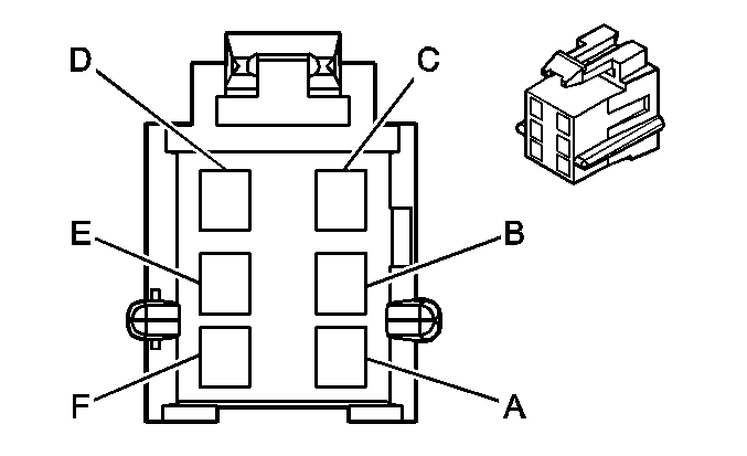
|
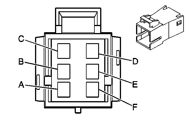
| ||||||||||||||
|---|---|---|---|---|---|---|---|---|---|---|---|---|---|---|---|
Connector Part Information |
| Connector Part Information |
| ||||||||||||
Pin | Wire Color | Circuit No. | Function | Pin | Wire Color | Circuit No. | Function | ||||||||
A | BK | 283 | Driver Seat Rear Vertical Motor Down Control | A | L-BU | 283 | Driver Seat Rear Vertical Motor Down Control | ||||||||
B | RD | 282 | Driver Seat Rear Vertical Motor Up Control | B | YE | 282 | Driver Seat Rear Vertical Motor Up Control | ||||||||
C | BK | 285 | Driver Seat Horizontal Motor Forward Control | C | TN | 285 | Driver Seat Horizontal Motor Forward Control | ||||||||
D | RD | 284 | Driver Seat Horizontal Motor Rearward Control | D | L-GN | 284 | Driver Seat Horizontal Motor Rearward Control | ||||||||
E | BK | 287 | Driver Seat Front Vertical Motor Down Control | E | D-BU | 287 | Driver Seat Front Vertical Motor Down Control | ||||||||
F | RD | 286 | Driver Seat Front Vertical Motor Up Control | F | D-GN | 286 | Driver Seat Front Vertical Motor Up Control | ||||||||
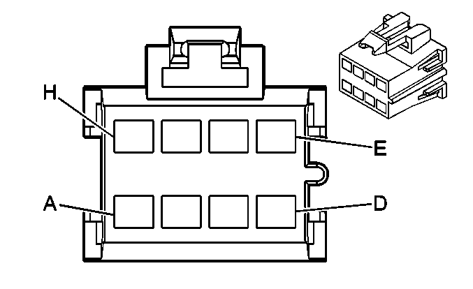
|
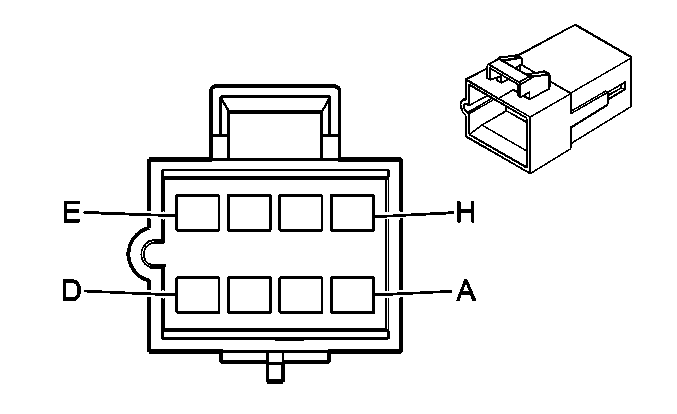
| ||||||||||||||
|---|---|---|---|---|---|---|---|---|---|---|---|---|---|---|---|
Connector Part Information |
| Connector Part Information |
| ||||||||||||
Pin | Wire Color | Circuit No. | Function | Pin | Wire Color | Circuit No. | Function | ||||||||
A | PU/WH | 611 | Driver Seat Lumbar Motor Forward Control | A | D-BU | 611 | Driver Seat Lumbar Motor Forward Control | ||||||||
B | L-BU | 1063 | Driver Seat Lumbar Horizontal Position Sensor Signal | B | YE/BK | 1063 | Driver Seat Lumbar Horizontal Position Sensor Signal | ||||||||
C | BN | 940 | 12-Volt Reference | C | WH | 940 | 12-Volt Reference | ||||||||
C | BN | 940 | 12-Volt Reference | ||||||||||||
D | TN/WH | 1258 | Driver Seat Torso Bolster Out Control | D | PU | 1258 | Driver Seat Torso Bolster Out Control | ||||||||
E | PK/BK | 1257 | Driver Seat Torso Bolster In Control | E | YE | 1257 | Driver Seat Torso Bolster In Control | ||||||||
F | D-BU/WH | 718 | Low Reference | F | BN/WH | 718 | Low Reference | ||||||||
F | D-BU/WH | 718 | Low Reference | ||||||||||||
G | PU/WH | 5700 | Drivers Seat Torso Bolster Position Sensor Signal | G | PU | 5700 | Drivers Seat Torso Bolster Position Sensor Signal | ||||||||
H | D-BU/WH | 610 | Driver Seat Lumbar Motor Rearward Control | H | PK | 610 | Driver Seat Lumbar Motor Rearward Control | ||||||||

|

| ||||||||||||||
|---|---|---|---|---|---|---|---|---|---|---|---|---|---|---|---|
Connector Part Information |
| Connector Part Information |
| ||||||||||||
Pin | Wire Color | Circuit No. | Function | Pin | Wire Color | Circuit No. | Function | ||||||||
A | BN | 2077 | Heated Seat Cushion Element Supply Voltage | A | RD/WH | 2077 | Heated Seat Cushion Element Supply Voltage | ||||||||
B | BK/RD | 2425 | Driver Heated Seat Back Temperature Sensor Signal | B | D-BU | 2425 | Driver Heated Seat Back Temperature Sensor Signal | ||||||||
C | YE | 2432 | Driver Heated Seat Back Element Supply Voltage | C | BN | 2432 | Driver Heated Seat Back Element Supply Voltage | ||||||||
D | BK | 2424 | Driver Heated Seat Back Element Control | D | PU | 2424 | Driver Heated Seat Back Element Control | ||||||||
E | BK/RD | 2426 | Low Reference | E | PK | 2751 | Low Reference | ||||||||
F | BK | 2078 | Heated Seat Cushion Element Control | F | L-GN | 2078 | Heated Seat Cushion Element Control | ||||||||

|

| ||||||||||||||
|---|---|---|---|---|---|---|---|---|---|---|---|---|---|---|---|
Connector Part Information |
| Connector Part Information |
| ||||||||||||
Pin | Wire Color | Circuit No. | Function | Pin | Wire Color | Circuit No. | Function | ||||||||
A | BN | 2479 | Passenger Heated Seat Element Supply Voltage | A | D-BU | 2479 | Passenger Heated Seat Element Supply Voltage | ||||||||
B | BK/RD | 5475 | Front Passenger Heated Seat Back Temperature Signal | B | D-BU | 5475 | Front Passenger Heated Seat Back Temperature Signal | ||||||||
C | YE | 2479 | Passenger Heated Seat Element Supply Voltage | C | D-BU | 2479 | Passenger Heated Seat Element Supply Voltage | ||||||||
D | BK | 2433 | Passenger Heated Seat Back Element Control | D | L-BU | 2433 | Passenger Heated Seat Back Element Control | ||||||||
E | BK/RD | 5476 | Low Reference | E | L-BU | 5476 | Low Reference | ||||||||
F | BK | 2480 | Passenger Heated Seat Cushion Element Control | F | PK | 2480 | Passenger Heated Seat Cushion Element Control | ||||||||

|

| ||||||||||||||
|---|---|---|---|---|---|---|---|---|---|---|---|---|---|---|---|
Connector Part Information |
| Connector Part Information |
| ||||||||||||
Pin | Wire Color | Circuit No. | Function | Pin | Wire Color | Circuit No. | Function | ||||||||
A | D-BU | 211 | Passenger Seat Lumbar Motor Forward Control | A | D-BU | 211 | Passenger Seat Lumbar Motor Forward Control | ||||||||
B | WH | 210 | Passenger Seat Lumbar Motor Rearward Control | B | WH | 210 | Passenger Seat Lumbar Motor Rearward Control | ||||||||
C | OG | 2462 | Passenger Torso Bolster Out Control | C | D-BU | 2462 | Passenger Torso Bolster Out Control | ||||||||
D | PK | 2427 | Passenger Torso Bolster In Control | D | L-BU | 2427 | Passenger Torso Bolster In Control | ||||||||
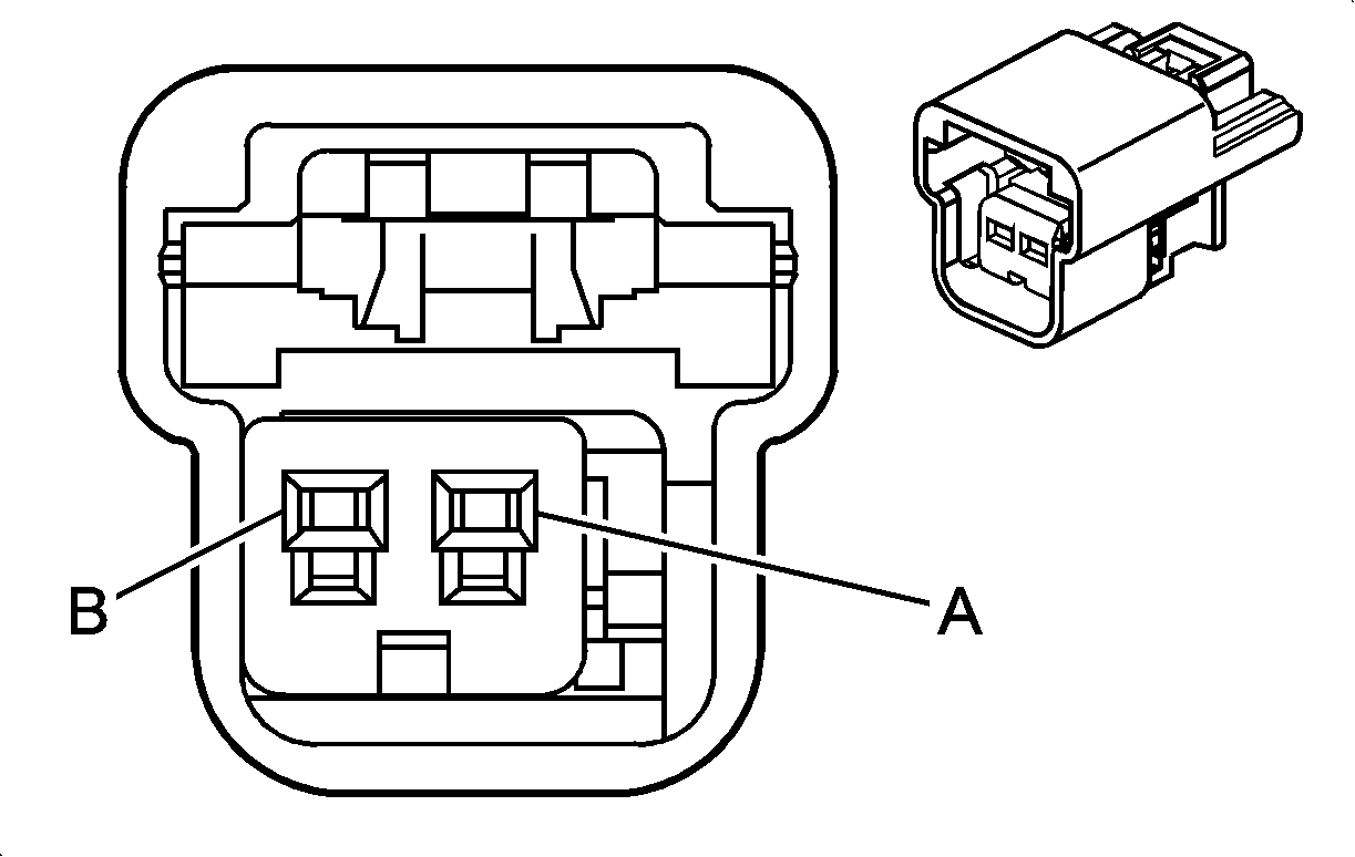
|
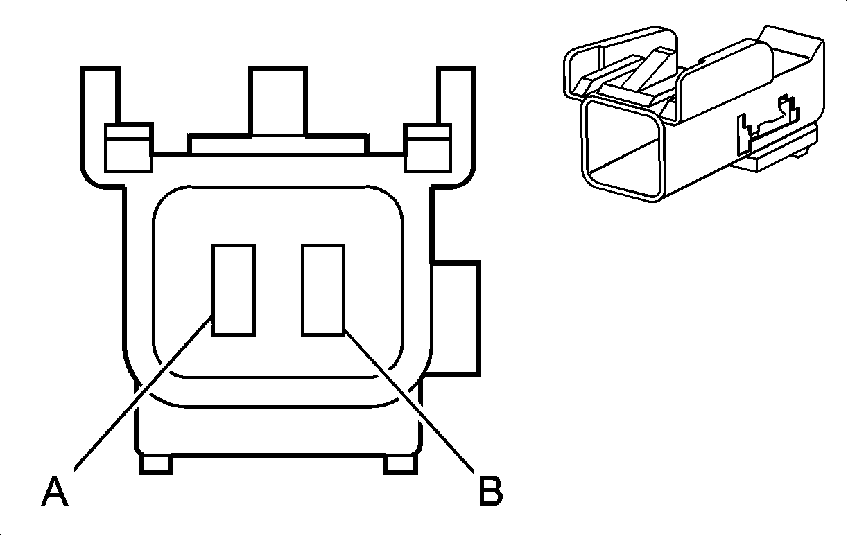
| ||||||||||||||
|---|---|---|---|---|---|---|---|---|---|---|---|---|---|---|---|
Connector Part Information |
| Connector Part Information |
| ||||||||||||
Pin | Wire Color | Circuit No. | Function | Pin | Wire Color | Circuit No. | Function | ||||||||
A | TN/BK | 371 | I/P Module Disable Switch - Signal | A | TN/BK | 371 | I/P Module Disable Switch - Signal | ||||||||
B | PK | 353 | I/P Module Suppression Indicator Control | B | PK | 353 | I/P Module Suppression Indicator Control | ||||||||
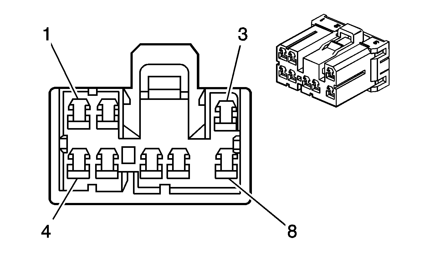
|
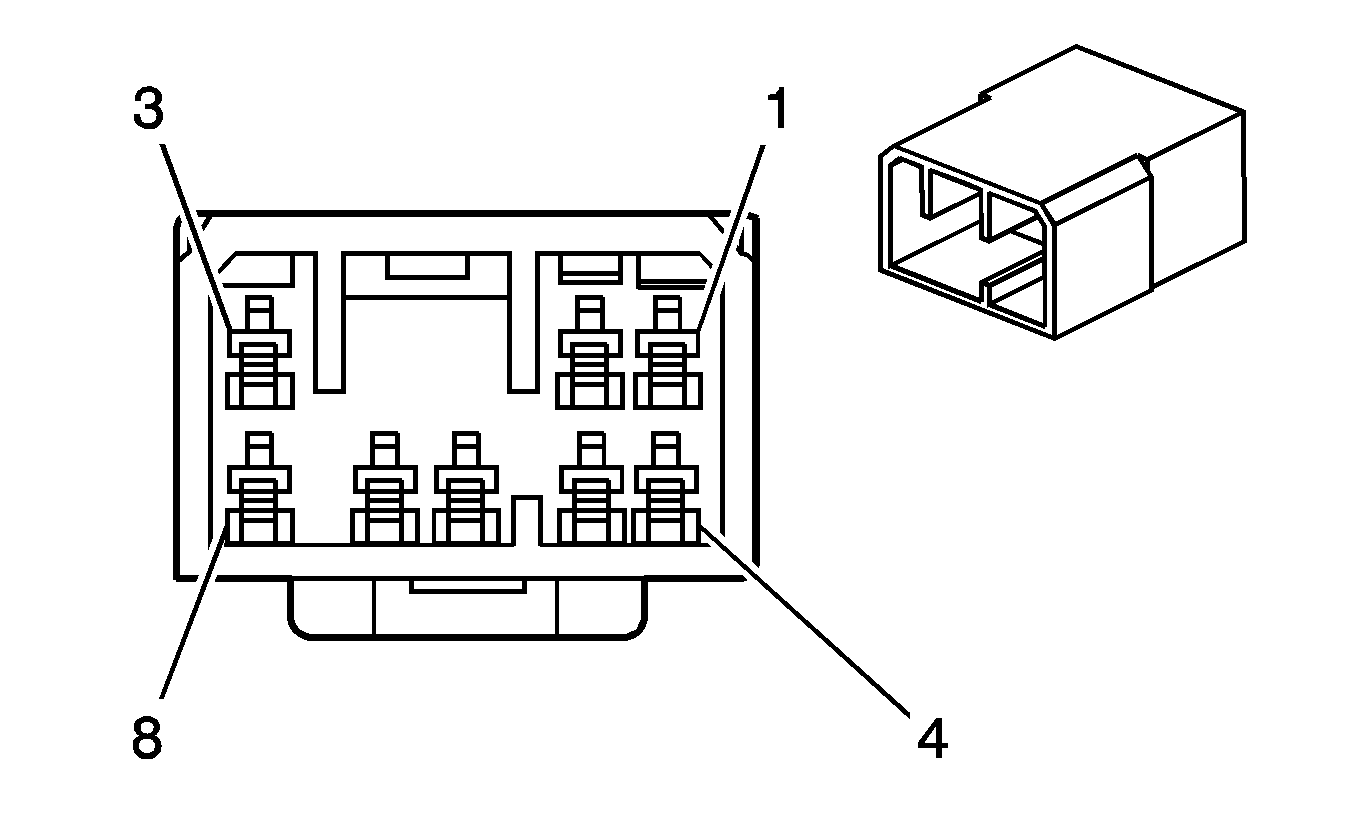
| ||||||||||||||
|---|---|---|---|---|---|---|---|---|---|---|---|---|---|---|---|
Connector Part Information |
| Connector Part Information |
| ||||||||||||
Pin | Wire Color | Circuit No. | Function | Pin | Wire Color | Circuit No. | Function | ||||||||
1 | TN/WH | 2500 | High Speed GMLAN Serial Data Bus+ | 1 | WH | 2500 | High Speed GMLAN Serial Data Bus+ | ||||||||
2 | TN | 2501 | High Speed GMLAN Serial Data Bus- | 2 | WH | 2501 | High Speed GMLAN Serial Data Bus- | ||||||||
3 | OG | 2740 | Battery Positive Voltage | 3 | WH | 2740 | Battery Positive Voltage | ||||||||
4-6 | -- | -- | Not Used | 4-6 | -- | -- | Not Used | ||||||||
7 | PK | 1939 | Ignition 1 Voltage | 7 | WH | 1939 | Ignition 1 Voltage | ||||||||
8 | PK | 1020 | Ignition 0 Voltage | 8 | WH | 1020 | Ignition 0 Voltage | ||||||||
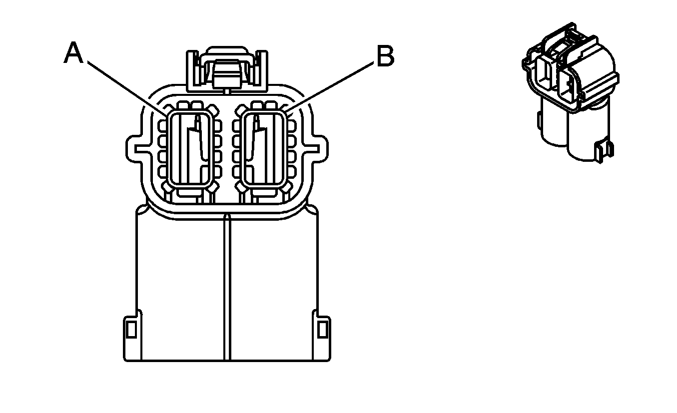
|
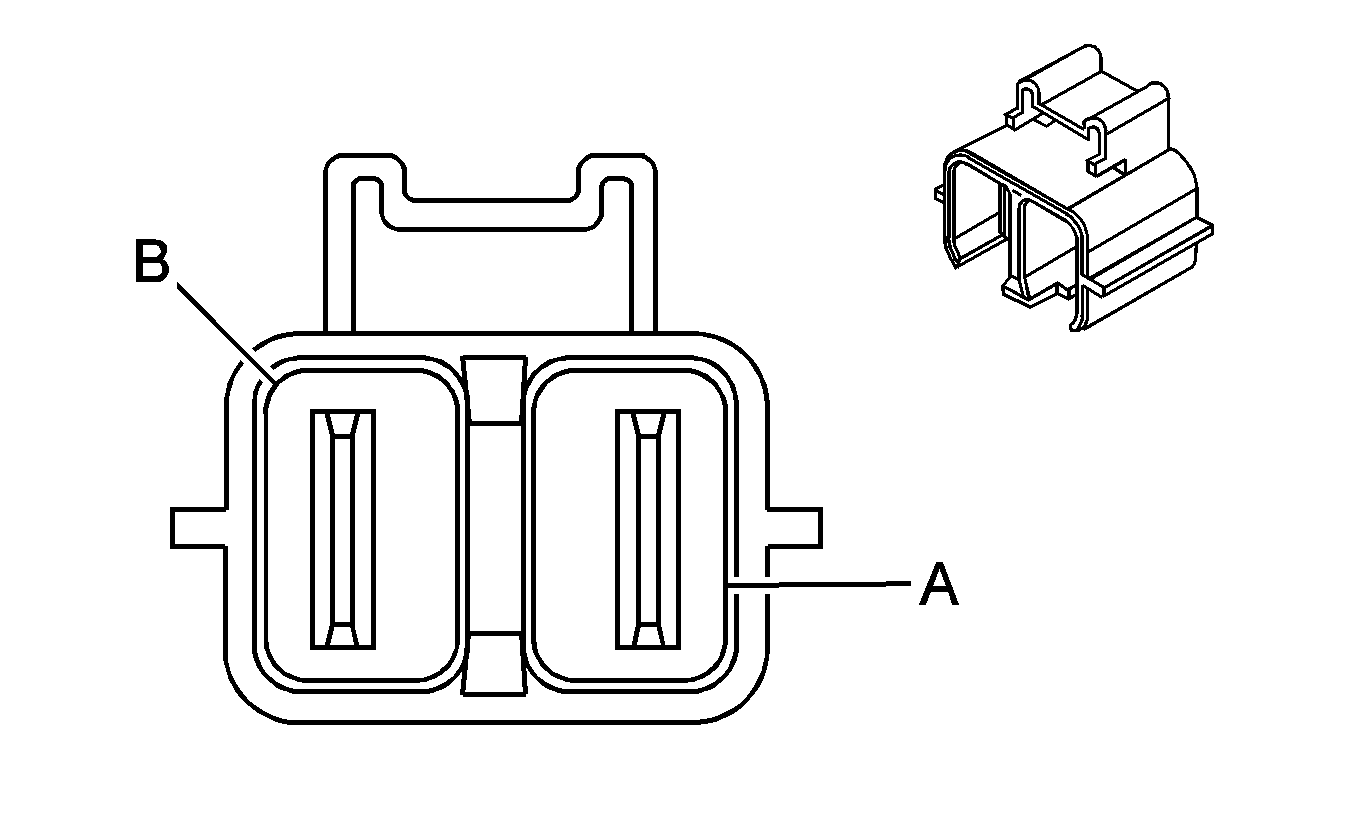
| ||||||||||||||
|---|---|---|---|---|---|---|---|---|---|---|---|---|---|---|---|
Connector Part Information |
| Connector Part Information |
| ||||||||||||
Pin | Wire Color | Circuit No. | Function | Pin | Wire Color | Circuit No. | Function | ||||||||
A | RD | 5084 | High Voltage Battery (+) | A | BK | 5084 | High Voltage Battery (+) | ||||||||
B | BK | 5691 | High Voltage Battery (-) | B | BK | 5691 | High Voltage Battery (-) | ||||||||
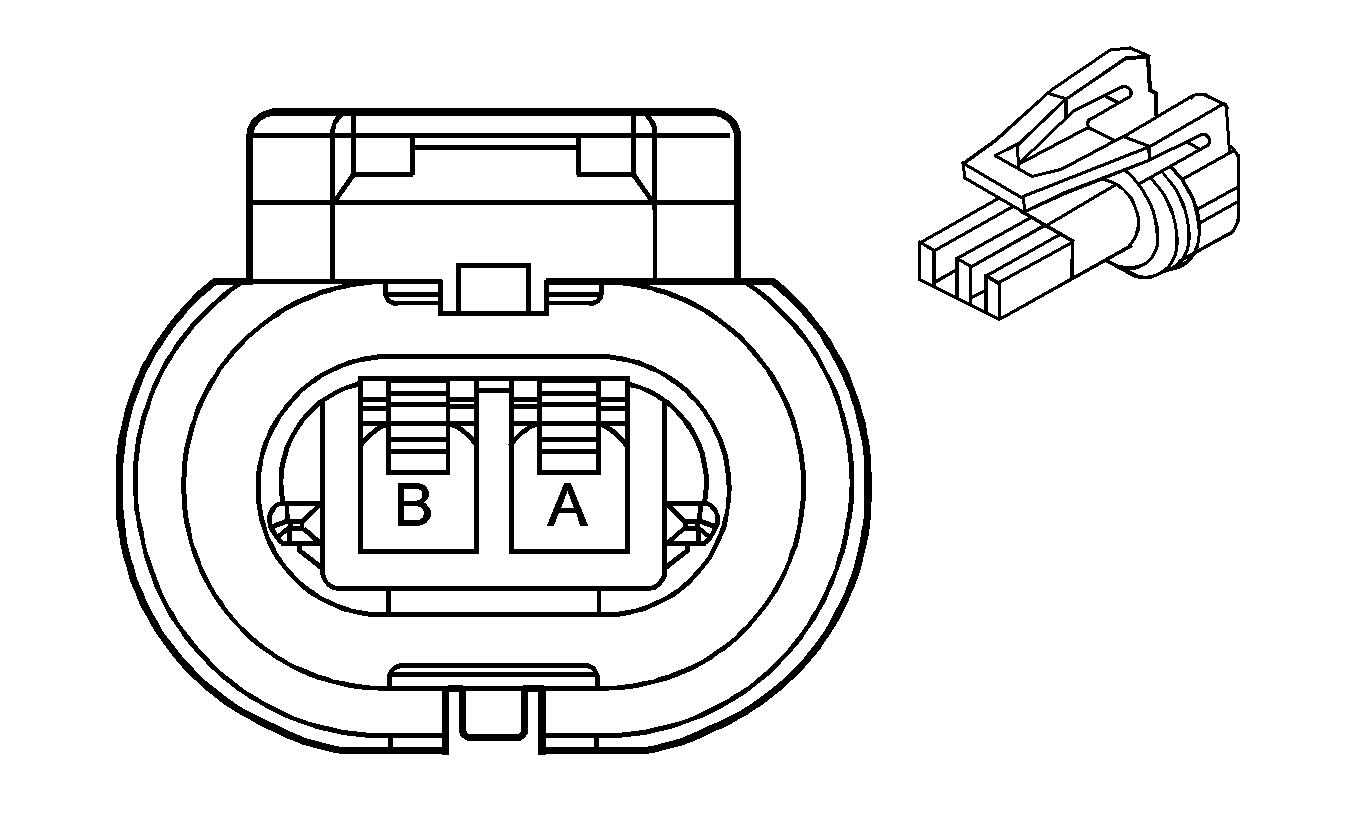
|
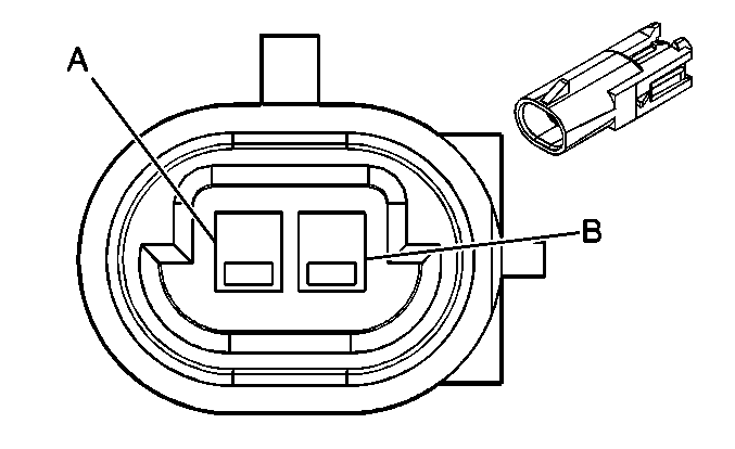
| ||||||||||||||
|---|---|---|---|---|---|---|---|---|---|---|---|---|---|---|---|
Connector Part Information |
| Connector Part Information |
| ||||||||||||
Pin | Wire Color | Circuit No. | Function | Pin | Wire Color | Circuit No. | Function | ||||||||
A | PU/WH | 821 | VSS High Signal | A | PU/WH | 821 | VSS High Signal | ||||||||
B | L-GN/BK | 822 | VSS Low Signal | B | L-GN/BK | 822 | VSS Low Signal | ||||||||
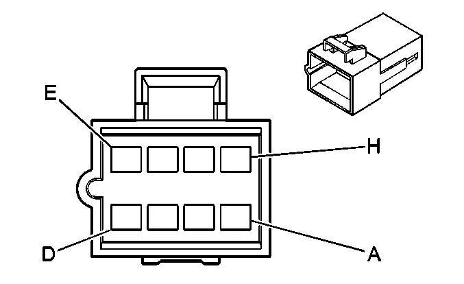
|

| ||||||||||||||
|---|---|---|---|---|---|---|---|---|---|---|---|---|---|---|---|
Connector Part Information |
| Connector Part Information |
| ||||||||||||
Pin | Wire Color | Circuit No. | Function | Pin | Wire Color | Circuit No. | Function | ||||||||
A | D-BU | 1353 | RAP Supply Voltage | A | D-BU | 1353 | RAP Supply Voltage | ||||||||
B | BK | 1050 | Ground | B | BK | 1050 | Ground | ||||||||
C | OG | 3840 | Battery Positive Voltage | C | OG | 3840 | Battery Positive Voltage | ||||||||
D | BN/WH | 230 | Instrument Panel Lamps Dimming Conrol | D | BN/WH | 230 | Instrument Panel Lamps Dimming Conrol | ||||||||
E-H | -- | -- | Not Used | E-H | -- | -- | Not Used | ||||||||
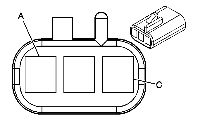
|
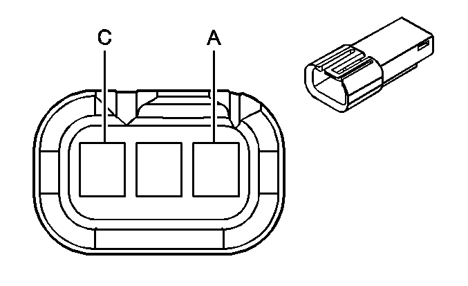
| ||||||||||||||
|---|---|---|---|---|---|---|---|---|---|---|---|---|---|---|---|
Connector Part Information |
| Connector Part Information |
| ||||||||||||
Pin | Wire Color | Circuit No. | Function | Pin | Wire Color | Circuit No. | Function | ||||||||
A | OG | 1732 | Inadvertent Power Supply Voltage | A | OG | -- | Inadvertent Power Supply Voltage | ||||||||
B | BK | 1050 | Ground | B | BK | -- | Ground | ||||||||
C | GY/BK | 690 | Courtesy Lamp Supply Voltage | C | GY | -- | Courtesy Lamp Supply Voltage | ||||||||

|

| ||||||||||||||
|---|---|---|---|---|---|---|---|---|---|---|---|---|---|---|---|
Connector Part Information |
| Connector Part Information |
| ||||||||||||
Pin | Wire Color | Circuit No. | Function | Pin | Wire Color | Circuit No. | Function | ||||||||
A | OG | 1732 | Inadvertent Power Supply Voltage | A | OG | -- | Inadvertent Power Supply Voltage | ||||||||
B | BK | 1050 | Ground | B | BK | -- | Ground | ||||||||
C | GY/BK | 690 | Courtesy Lamp Supply Voltage | C | GY | -- | Courtesy Lamp Supply Voltage | ||||||||
D | BN/WH | 230 | Instrument Panel Lamps Dimming Control | D | WH | -- | Instrument Panel Lamps Dimming Control | ||||||||
E | OG | 4540 | Battery Positive Voltage | E | OG | -- | Battery Positive Voltage | ||||||||
F | -- | -- | Not Used | F | -- | -- | Not Used | ||||||||

|

| ||||||||||||||
|---|---|---|---|---|---|---|---|---|---|---|---|---|---|---|---|
Connector Part Information |
| Connector Part Information |
| ||||||||||||
Pin | Wire Color | Circuit No. | Function | Pin | Wire Color | Circuit No. | Function | ||||||||
A | BK | 289 | Passenger Seat Rear Vertical Motor Down Control | A | L-BU | 289 | Passenger Seat Rear Vertical Motor Down Control | ||||||||
B | RD | 288 | Passenger Seat Rear Vertical Motor Up Control | B | YE | 288 | Passenger Seat Rear Vertical Motor Up Control | ||||||||
C | BK | 290 | Passenger Seat Horizontal Motor Rearward Control | C | L-GN | 290 | Passenger Seat Horizontal Motor Rearward Control | ||||||||
D | RD | 296 | Passenger Seat Horizontal Motor Forward Control | D | TN | 296 | Passenger Seat Horizontal Motor Forward Control | ||||||||
E | BK | 298 | Passenger Seat Front Vertical Motor Down Control | E | D-BU | 298 | Passenger Seat Front Vertical Motor Down Control | ||||||||
F | RD | 297 | Passenger Seat Front Vertical Motor Up Control | F | D-GN | 297 | Passenger Seat Front Vertical Motor Up Control | ||||||||

|

| ||||||||||||||
|---|---|---|---|---|---|---|---|---|---|---|---|---|---|---|---|
Connector Part Information |
| Connector Part Information |
| ||||||||||||
Pin | Wire Color | Circuit No. | Function | Pin | Wire Color | Circuit No. | Function | ||||||||
A | GY/BK | 1186 | Power Window Relay Right Rear Up Control (YE9) | A | WH | 1185 | Power Window Relay Right Rear Up Control (YE9) | ||||||||
B | D-GN | 1188 | Power Window Relay Left Rear Up Control (YE9) | B | YE | 1187 | Power Window Relay Left Rear Up Control (YE9) | ||||||||
C | L-GN | 2266 | Power Window Lockout Right Rear Control (YE9) | C | L-BU | 2265 | Power Window Lockout Right Rear Control (YE9) | ||||||||
D | -- | -- | Not Used | D | -- | -- | Not Used | ||||||||
E | BN/WH | 230 | Instrument Panel Lamps Dimming Control (YE9) | E | BN/WH | 230 | Instrument Panel Lamps Dimming Control (YE9) | ||||||||
F | BK | 1250 | Ground (YE9) | F | BK | 1150 | Ground (YE9) | ||||||||
G | OG | 1340 | Battery Positive Voltage (YE9) | G | OG | 1240 | Battery Positive Voltage (YE9) | ||||||||
H | L-GN/BK | 748 | Right Rear Door Ajar Switch Signal | H | L-BU/BK | 747 | Right Rear Door Ajar Switch Signal | ||||||||
J | -- | -- | Not Used | J | -- | -- | Not Used | ||||||||
K | L-BU | 115 | Right Rear Speaker Output (-) | K | YE | 116 | Right Rear Speaker Output (-) | ||||||||
L | D-BU | 46 | Right Rear Speaker Output (+) | L | BN | 199 | Right Rear Speaker Output (+) | ||||||||
M | BK | 1250 | Ground | M | BK | 1150 | Ground | ||||||||
N | TN | 294 | Door Lock Actuator Unlock Control | N | TN | 294 | Door Lock Actuator Unlock Control | ||||||||
P | GY | 295 | Door Lock Actuator Lock Control | P | GY | 295 | Door Lock Actuator Lock Control | ||||||||
R-T | -- | -- | Not Used | R-T | -- | -- | Not Used | ||||||||

|

| ||||||||||||||
|---|---|---|---|---|---|---|---|---|---|---|---|---|---|---|---|
Connector Part Information |
| Connector Part Information |
| ||||||||||||
Pin | Wire Color | Circuit No. | Function | Pin | Wire Color | Circuit No. | Function | ||||||||
A | OG | 1440 | Battery Positive Voltage (AG2) | A | OG | 1440 | Battery Positive Voltage (AG2) | ||||||||
B | PK | 2480 | Passenger Heated Seat Cushion Element Control (KA1) | B | PK | 2480 | Passenger Heated Seat Cushion Element Control (KA1) | ||||||||
C | L-BU | 2433 | Passenger Heated Seat Back Element Control (KA1) | C | L-BU | 2433 | Passenger Heated Seat Back Element Control (KA1) | ||||||||
D | -- | -- | Not Used | D | -- | -- | Not Used | ||||||||
E | RD | 1362 | Seat Belt Switch - Right - Signal (AL0) | E | OG | 1362 | Seat Belt Switch - Right - Signal (AL0) | ||||||||
F | L-BU | 5056 | Seat Position Switch - Right - Signal (AL0) | F | L-BU | 5056 | Seat Position Switch - Right - Signal (AL0) | ||||||||
G | D-BU | 5475 | Front Passenger Heated Seat Back Element Control (KA1) | G | D-BU | 5475 | Front Passenger Heated Seat Back Element Control (KA1) | ||||||||
H | D-BU | 2479 | Passenger Seat Heater Element Supply Voltage (KA1) | H | D-BU | 2479 | Passenger Seat Heater Element Supply Voltage (KA1) | ||||||||
H | D-BU | 2479 | Passenger Seat Heater Element Supply Voltage (KA1) | ||||||||||||
J | D-BU | 1363 | Seat Belt Indicator Control (w/o AL0) | J | YE | 234 | Seat Belt Indicator Control (AL0) | ||||||||
J | YE | 234 | Seat Belt Indicator Control (AL0) | ||||||||||||
K | PK | 2306 | Serial Data (AL0) | K | PK | 2306 | Serial Data (AL0) | ||||||||
L | D-BU | 2307 | Passenger Air Bag On Indicator Control (AL0) | L | D-BU | 2307 | Passenger Air Bag On Indicator Control (AL0) | ||||||||
M | D-GN | 2308 | Passenger Air Bag Off Indicator Control (AL0) | M | D-GN | 2308 | Passenger Air Bag Off Indicator Control (AL0) | ||||||||
N | YE | 1139 | Ignition 1 Voltage (AL0) | N | YE | 1139 | Ignition 1 Voltage (AL0) | ||||||||
P | BK | 2351 | Ground (AL0) | P | BK | 2351 | Ground (AL0) | ||||||||
R | L-BU | 5476 | Low Reference (KA1) | R | L-BU | 5476 | Low Reference (KA1) | ||||||||
S | BK | 1250 | Ground (KA1) | S | BK | 1250 | Ground (KA1) | ||||||||

|

| ||||||||||||||
|---|---|---|---|---|---|---|---|---|---|---|---|---|---|---|---|
Connector Part Information |
| Connector Part Information |
| ||||||||||||
Pin | Wire Color | Circuit No. | Function | Pin | Wire Color | Circuit No. | Function | ||||||||
A | BN/WH | 2609 | Park Lamps Supply Voltage | A | BN/WH | 2609 | Park Lamps Supply Voltage | ||||||||
B | BK | 1750 | Ground | B | BK | 1750 | Ground | ||||||||

|

| ||||||||||||||
|---|---|---|---|---|---|---|---|---|---|---|---|---|---|---|---|
Connector Part Information |
| Connector Part Information |
| ||||||||||||
Pin | Wire Color | Circuit No. | Function | Pin | Wire Color | Circuit No. | Function | ||||||||
A | BN | 2509 | Park Lamps Supply Voltage | A | BN | 2509 | Park Lamps Supply Voltage | ||||||||
B | BK | 1750 | Ground | B | BK | 1750 | Ground | ||||||||
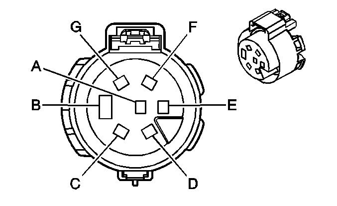
|
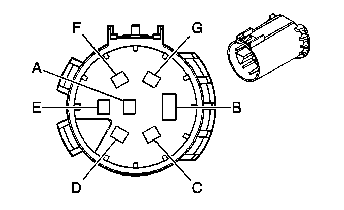
| ||||||||||||||
|---|---|---|---|---|---|---|---|---|---|---|---|---|---|---|---|
Connector Part Information |
| Connector Part Information |
| ||||||||||||
Pin | Wire Color | Circuit No. | Function | Pin | Wire Color | Circuit No. | Function | ||||||||
A | L-GN | 1624 | Trailer Backup Lamps Supply Voltage | A | L-GN | 1624 | Trailer Backup Lamps Supply Voltage | ||||||||
B | BK | 1550 | Ground (30 Series Except Chassis Cab) | B | WH | 22 | Ground | ||||||||
BK | 1650 | Ground (30 Series Chassis Cab) | |||||||||||||
C | D-BU | 47 | Trailer Auxiliary Supply Voltage | C | D-BU | 47 | Trailer Auxiliary Supply Voltage | ||||||||
D | D-GN | 1619 | Trailer Right Rear Turn/Stop Lamps Supply Voltage | D | D-GN | 1619 | Trailer Right Rear Turn/Stop Lamps Supply Voltage | ||||||||
E | RD | 742 | Battery Positive Voltage | E | RD | 742 | Battery Positive Voltage | ||||||||
F | BN | 2109 | Trailer Park Lamps Supply Voltage | F | BN | 2109 | Trailer Park Lamps Supply Voltage | ||||||||
G | YE | 1618 | Trailer Left Rear Turn/Stop Lamps Supply Voltage | G | YE | 1618 | Trailer Left Rear Turn/Stop Lamps Supply Voltage | ||||||||

|

| ||||||||||||||
|---|---|---|---|---|---|---|---|---|---|---|---|---|---|---|---|
Connector Part Information |
| Connector Part Information |
| ||||||||||||
Pin | Wire Color | Circuit No. | Function | Pin | Wire Color | Circuit No. | Function | ||||||||
A | L-BU | 1620 | Stop Lamp Switch Signals | A | L-BU | 1620 | Stop Lamp Switch Signals | ||||||||

|
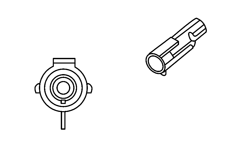
| ||||||||||||||
|---|---|---|---|---|---|---|---|---|---|---|---|---|---|---|---|
Connector Part Information |
| Connector Part Information |
| ||||||||||||
Pin | Wire Color | Circuit No. | Function | Pin | Wire Color | Circuit No. | Function | ||||||||
A | BN/WH | 900 | Blackout (B/O) Marker Lamp (RF) Supply Voltage | A | BK | -- | Blackout (B/O) Marker Lamp (RF) Supply Voltage | ||||||||

|

| ||||||||||||||
|---|---|---|---|---|---|---|---|---|---|---|---|---|---|---|---|
Connector Part Information |
| Connector Part Information |
| ||||||||||||
Pin | Wire Color | Circuit No. | Function | Pin | Wire Color | Circuit No. | Function | ||||||||
A | BN/WH | 900 | Blackout (B/O) Marker Lamp (LF) Supply Voltage | A | BK | -- | Blackout (B/O) Marker Lamp (LF) Supply Voltage | ||||||||

|

| ||||||||||||||
|---|---|---|---|---|---|---|---|---|---|---|---|---|---|---|---|
Connector Part Information |
| Connector Part Information |
| ||||||||||||
Pin | Wire Color | Circuit No. | Function | Pin | Wire Color | Circuit No. | Function | ||||||||
A | BK | -- | Blackout (B/O) Headlamp Supply Voltage | A | TN/WH | 901 | Blackout (B/O) Headlamp Supply Voltage | ||||||||

|

| ||||||||||||||
|---|---|---|---|---|---|---|---|---|---|---|---|---|---|---|---|
Connector Part Information |
| Connector Part Information |
| ||||||||||||
Pin | Wire Color | Circuit No. | Function | Pin | Wire Color | Circuit No. | Function | ||||||||
A | TN/WH | 901 | Blackout (B/O) Head Lamp Supply Voltage | A | TNWH | 901 | Blackout (B/O) Head Lamp Supply Voltage | ||||||||
B | BN/WH | 900 | Blackout (B/O) Marker Lamps Supply Voltage | B | BN/WH | 900 | Blackout (B/O) Marker Lamps Supply Voltage | ||||||||

| |||||||||||||||
|---|---|---|---|---|---|---|---|---|---|---|---|---|---|---|---|
Connector Part Information |
| Connector Part Information |
| ||||||||||||
Pin | Wire Color | Circuit No. | Function | Pin | Wire Color | Circuit No. | Function | ||||||||
A | WH | 1080 | Park Lamps Supply Voltage | A | WH | 1080 | Park Lamps Supply Voltage | ||||||||
B | BK/WH | 1969 | Head Lamps (Hi Beam) Supply Voltage | B | BK/WH | 1969 | Head Lamps (Hi Beam) Supply Voltage | ||||||||
C | PK/WH | 1970 | Head Lamp (Low Beam) Supply Voltage | C | PK/WH | 1970 | Head Lamp (Low Beam) Supply Voltage | ||||||||
D | PK | 639 | Turn Signals Supply Voltage | D | PK | 639 | Turn Signals Supply Voltage | ||||||||

| |||||||||||||||
|---|---|---|---|---|---|---|---|---|---|---|---|---|---|---|---|
Connector Part Information |
| Connector Part Information |
| ||||||||||||
Pin | Wire Color | Circuit No. | Function | Pin | Wire Color | Circuit No. | Function | ||||||||
A | L GN/BK | 592 | DRL Supply Voltage | A | L GN/BK | 592 | DRL Supply Voltage | ||||||||
B | DK GN | 1329 | Horn Supply Voltage | B | D GN | 1329 | Horn Supply Voltage | ||||||||
C | OG | 304 | Radio Supply Voltage | C | OG | 304 | Radio Supply Voltage | ||||||||

|

| ||||||||||||||
|---|---|---|---|---|---|---|---|---|---|---|---|---|---|---|---|
Connector Part Information |
| Connector Part Information |
| ||||||||||||
Pin | Wire Color | Circuit No. | Function | Pin | Wire Color | Circuit No. | Function | ||||||||
A | OG | 912 | Supply Voltage to Relay Module | A | OG | 912 | Supply Voltage to Relay Module | ||||||||

| |||||||||||||||
|---|---|---|---|---|---|---|---|---|---|---|---|---|---|---|---|
Connector Part Information |
| Connector Part Information |
| ||||||||||||
Pin | Wire Color | Circuit No. | Function | Pin | Wire Color | Circuit No. | Function | ||||||||
A | BN/WH | 900 | Rear Marker Lamp Supply Voltage | A | BN/WH | 900 | Rear Marker Lamp Supply Voltage | ||||||||
B | D GN/WH | 902 | Rear Stoplamp Supply Voltage | B | D GN/WH | 902 | Rear Stoplamp Supply Voltage | ||||||||

|

| ||||||||||||||
|---|---|---|---|---|---|---|---|---|---|---|---|---|---|---|---|
Connector Part Information |
| Connector Part Information |
| ||||||||||||
Pin | Wire Color | Circuit No. | Function | Pin | Wire Color | Circuit No. | Function | ||||||||
A | BN | 9 | Supply Voltage to TPMS Gage Dimming | A | BN | 9 | Supply Voltage to TPMS Gage Dimming | ||||||||

|

| ||||||||||||||
|---|---|---|---|---|---|---|---|---|---|---|---|---|---|---|---|
Connector Part Information |
| Connector Part Information |
| ||||||||||||
Pin | Wire Color | Circuit No. | Function | Pin | Wire Color | Circuit No. | Function | ||||||||
A | BN/WH | 803 | To Rear Topper Dome Switch | A | BN | 800 | From Front Topper Dome Switch | ||||||||
B | BN | 800 | To Rear Topper Dome Switch | B | BN/WH | 803 | From Front Topper Dome Switch | ||||||||

|

| ||||||||||||||
|---|---|---|---|---|---|---|---|---|---|---|---|---|---|---|---|
Connector Part Information |
| Connector Part Information |
| ||||||||||||
Pin | Wire Color | Circuit No. | Function | Pin | Wire Color | Circuit No. | Function | ||||||||
A | WH | 17 | Brake Light Switch | A | WH | 17 | Blackout (B/O) Service Switch | ||||||||
B | -- | -- | Not Used | B | -- | -- | Not Used | ||||||||
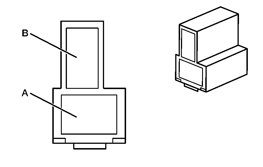
|
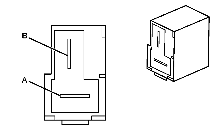
| ||||||||||||||
|---|---|---|---|---|---|---|---|---|---|---|---|---|---|---|---|
Connector Part Information |
| Connector Part Information |
| ||||||||||||
Pin | Wire Color | Circuit No. | Function | Pin | Wire Color | Circuit No. | Function | ||||||||
A | BN | 8008 | Volt Gage Supply Voltage | A | BN | 8008 | Volt Gage Supply Voltage | ||||||||
B | BK | 150 | Ground | B | BK | 150 | Ground | ||||||||

|

| ||||||||||||||
|---|---|---|---|---|---|---|---|---|---|---|---|---|---|---|---|
Connector Part Information |
| Connector Part Information |
| ||||||||||||
Pin | Wire Color | Circuit No. | Function | Pin | Wire Color | Circuit No. | Function | ||||||||
A | GY/BK | 690 | CTSY Supply Voltage | A | GY/BK | 690 | CTRY Supply Voltage | ||||||||
B | OG/BK | 1732 | Inadvertent Power Supply Voltage | B | OG/BK | 1732 | Inadvertent Power Supply Voltage | ||||||||
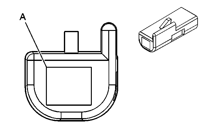
|
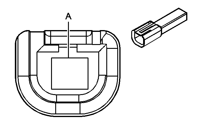
| ||||||||||||||
|---|---|---|---|---|---|---|---|---|---|---|---|---|---|---|---|
Connector Part Information |
| Connector Part Information |
| ||||||||||||
Pin | Wire Color | Circuit No. | Function | Pin | Wire Color | Circuit No. | Function | ||||||||
A | GN | 24 | Backup Lamp Supply Voltage | A | L GY/BK | 24 | Backup Lamp Supply Voltage | ||||||||
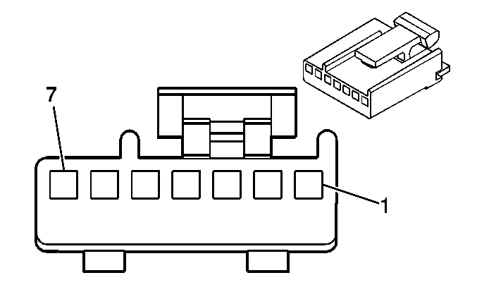
|
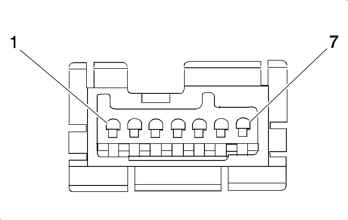
| ||||||||||||||
|---|---|---|---|---|---|---|---|---|---|---|---|---|---|---|---|
Connector Part Information |
| Connector Part Information |
| ||||||||||||
Pin | Wire Color | Circuit No. | Function | Pin | Wire Color | Circuit No. | Function | ||||||||
1 | GY | 1056 | Dimmer Switch 5V Reference Voltage from Dimming Relay | 1 | GY | 1056 | Dimmer Switch 5V Reference Voltage from Dimming Relay | ||||||||
2 | OG/BK | 2090 | Dimmer Switch Signal from Dimming Relay | 2 | OG/WH | 2090 | Dimmer Switch Signal from Dimming Relay | ||||||||
3 | GY/BK | 2226 | Dimmer Switch Low Reference from Dimming Relay | 3 | GY/BK | 2226 | Dimmer Switch Low Reference from Dimming Relay | ||||||||
4 | -- | -- | Not Used | 4 | -- | -- | Not Used | ||||||||
5 | GY | 1056 | Dimmer Switch 5V Reference Voltage from BCM | 5 | GY | 1056 | Dimmer Switch 5V Reference Voltage from BCM | ||||||||
6 | YE/BK | 2090 | Dimmer Switch Signal from BCM | 6 | YE/BK | 2090 | Dimmer Switch Signal from BCM | ||||||||
7 | GY/BK | 2226 | Dimmer Switch Signal from BCM | 7 | GY/BK | 2226 | Dimmer Switch Signal from BCM | ||||||||

|

| ||||||||||||||
|---|---|---|---|---|---|---|---|---|---|---|---|---|---|---|---|
Connector Part Information |
| Connector Part Information |
| ||||||||||||
Pin | Wire Color | Circuit No. | Function | Pin | Wire Color | Circuit No. | Function | ||||||||
A | OG | 912 | Blackout (B/O) Service Switch Voltage | A | OG | 912 | Blackout (B/O) Service Switch Voltage | ||||||||
B | BK | 150 | Ground | B | BK | 150 | Ground | ||||||||

|

| ||||||||||||||
|---|---|---|---|---|---|---|---|---|---|---|---|---|---|---|---|
Connector Part Information |
| Connector Part Information |
| ||||||||||||
Pin | Wire Color | Circuit No. | Function | Pin | Wire Color | Circuit No. | Function | ||||||||
A | OG | 912 | Supply Voltage to Relay Module | A | OG | 912 | Supply Voltage to Relay Module | ||||||||
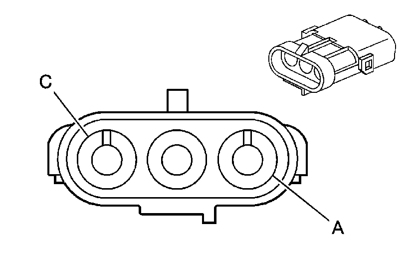
|
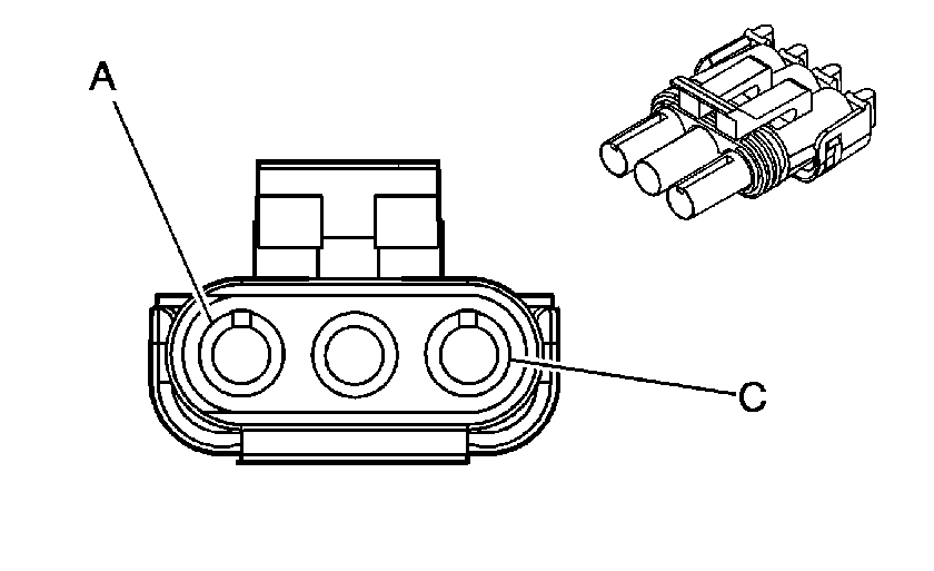
| ||||||||||||||
|---|---|---|---|---|---|---|---|---|---|---|---|---|---|---|---|
Connector Part Information |
| Connector Part Information |
| ||||||||||||
Pin | Wire Color | Circuit No. | Function | Pin | Wire Color | Circuit No. | Function | ||||||||
A | BN | 30 | Blackout (B/O) Marker Lamps | A | BN | 30 | Blackout (B/O) Marker Lamps | ||||||||
B | YE | 18 | S/T Lamp Feed (Left) | B | YE | 18 | S/T Lamp Feed (Left) | ||||||||
C | BK | 150 | Ground | C | BK | 150 | Ground | ||||||||

|

| ||||||||||||||
|---|---|---|---|---|---|---|---|---|---|---|---|---|---|---|---|
Connector Part Information |
| Connector Part Information |
| ||||||||||||
Pin | Wire Color | Circuit No. | Function | Pin | Wire Color | Circuit No. | Function | ||||||||
A | BN | 9 | Park Lamp Feed | A | BN | 9 | Park Lamp Feed | ||||||||
B | GN | 30 | Blackout (B/O) Stoplamps | B | D GN | 30 | Blackout (B/O) Stoplamps | ||||||||
C | D GN | 19 | S/T Lamps (Right) | C | D GN | 19 | S/T Lamps (Right) | ||||||||
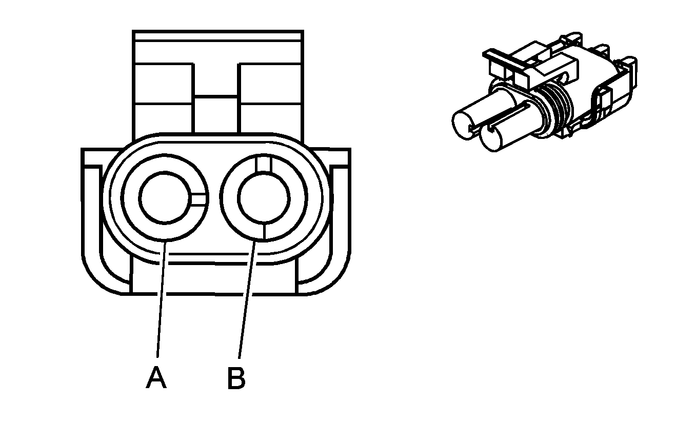
|
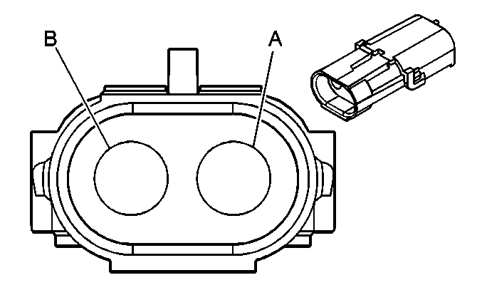
| ||||||||||||||
|---|---|---|---|---|---|---|---|---|---|---|---|---|---|---|---|
Connector Part Information |
| Connector Part Information |
| ||||||||||||
Pin | Wire Color | Circuit No. | Function | Pin | Wire Color | Circuit No. | Function | ||||||||
A | GN/WH | 902 | Right Rear Blackout (B/O) Stoplamps | A | GN/WH | 902 | Right Rear Blackout (B/O) Stoplamps | ||||||||
B | BN/WH | 900 | Right Rear Blackout (B/O) Marker Lamps | B | BN/WH | 900 | Right Rear Blackout (B/O) Marker Lamps | ||||||||

|

| ||||||||||||||
|---|---|---|---|---|---|---|---|---|---|---|---|---|---|---|---|
Connector Part Information |
| Connector Part Information |
| ||||||||||||
Pin | Wire Color | Circuit No. | Function | Pin | Wire Color | Circuit No. | Function | ||||||||
A | GN/WH | 902 | Left Rear Blackout (B/O) Stoplamps | A | GN/WH | 902 | Left Rear Blackout (B/O) Stoplamps | ||||||||
B | BN/WH | 900 | Left Rear Blackout (B/O) Marker Lamps | B | BN/WH | 900 | Left Rear Blackout (B/O) Marker Lamps | ||||||||

|

| ||||||||||||||
|---|---|---|---|---|---|---|---|---|---|---|---|---|---|---|---|
Connector Part Information |
| Connector Part Information |
| ||||||||||||
Pin | Wire Color | Circuit No. | Function | Pin | Wire Color | Circuit No. | Function | ||||||||
A | BK | 1050 | CHML Supply Voltage | A | RD | 1620 | CHML Supply Voltage | ||||||||
B | BU | 1050 | Ground | B | BK | 1050 | Ground | ||||||||

| |||||||||||||||
|---|---|---|---|---|---|---|---|---|---|---|---|---|---|---|---|
Connector Part Information |
| Connector Part Information |
| ||||||||||||
Pin | Wire Color | Circuit No. | Function | Pin | Wire Color | Circuit No. | Function | ||||||||
A | BN/WH | 900 | Rear Marker Lamp Supply Voltage | A | BN/WH | 900 | Rear Marker Lamp Supply Voltage | ||||||||
B | D GN/WH | 902 | Rear Stoplamp Supply Voltage | B | D GN/WH | 902 | Rear Stoplamp Supply Voltage | ||||||||

|

| ||||||||||||||
|---|---|---|---|---|---|---|---|---|---|---|---|---|---|---|---|
Connector Part Information |
| Connector Part Information |
| ||||||||||||
Pin | Wire Color | Circuit No. | Function | Pin | Wire Color | Circuit No. | Function | ||||||||
A | L GN | 1624 | Trailer Backup Lamps Supply Voltage | A | L GN | 1624 | Trailer Backup Lamps Supply Voltage | ||||||||
B | BK | 1750 | Ground | B | BK | 1750 | Ground | ||||||||
C | BU | 47 | Trailer Auxiliary Supply Voltage | C | BU | 47 | Trailer Auxiliary Supply Voltage | ||||||||
D | D GN | 1619 | S/T Lamps (Right) | D | D GN | 1619 | S/T Lamps (Right) | ||||||||
E | RD | 742 | Battery Positive Voltage | E | RD | 742 | Battery Positive Voltage | ||||||||
F | BN | 915 | Park Lamps | F | BN | 915 | Park Lamps | ||||||||
G | YE | 1618 | S/T Lamps (Left) | G | YE | 1618 | S/T Lamps (Left) | ||||||||

|

| ||||||||||||||
|---|---|---|---|---|---|---|---|---|---|---|---|---|---|---|---|
Connector Part Information |
| Connector Part Information |
| ||||||||||||
Pin | Wire Color | Circuit No. | Function | Pin | Wire Color | Circuit No. | Function | ||||||||
A | L GN | 1624 | Trailer Backup Lamps Supply Voltage | A | L GN | 1624 | Trailer Backup Lamps Supply Voltage | ||||||||
B | BK | 1750 | Ground | B | BK | 1750 | Ground | ||||||||
C | BU | 47 | Trailer Auxiliary Supply Voltage | C | BU | 47 | Trailer Auxiliary Supply Voltage | ||||||||
D | D GN | 1619 | S/T Lamps (Right) | D | D GN | 1619 | S/T Lamps (Right) | ||||||||
E | RD | 742 | Battery Positive Voltage | E | RD | 742 | Battery Positive Voltage | ||||||||
F | BN | 915 | Park Lamps | F | BN | 915 | Park Lamps | ||||||||
G | YE | 1618 | S/T Lamps (Left) | G | YE | 1618 | S/T Lamps (Left) | ||||||||

|

| ||||||||||||||
|---|---|---|---|---|---|---|---|---|---|---|---|---|---|---|---|
Connector Part Information |
| Connector Part Information |
| ||||||||||||
Pin | Wire Color | Circuit No. | Function | Pin | Wire Color | Circuit No. | Function | ||||||||
A | RD | 87 | Power to Trailer Relays | A | RD | 802 | Power to Trailer Relays | ||||||||
