For 1990-2009 cars only
Removal Procedure
- Raise the vehicle. Refer to Lifting and Jacking the Vehicle in General Information in 2005 C/K Truck Service Manual.
- Remove the tire and wheel. Refer to Tire and Wheel Removal and Installation in Tires and Wheels in 2005 C/K Truck Service Manual.
- Remove the jounce shock absorber. Refer to Jounce Shock Absorber Replacement .
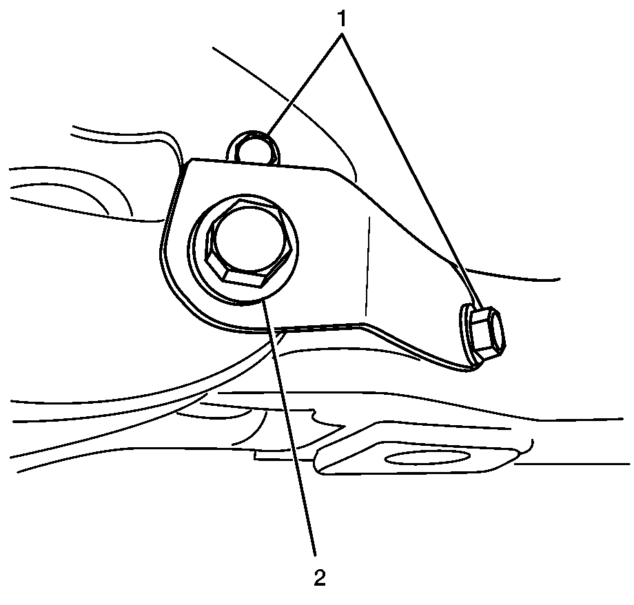
- Remove the 2 control arm brace bolts (1).
- Remove the control arm pivot bolt (2) and washer.
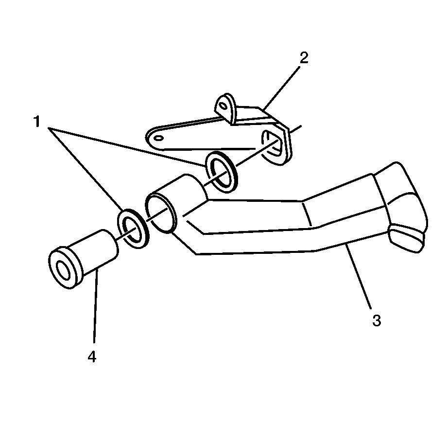
- Remove the control arm brace (2).
- Remove the outer shim (1).
- Remove the control arm (3).
- Inspect both shims (1) and pivot nut (4). Replace if worn.
Caution: Refer to Vehicle Lifting Caution in the Preface section.


Installation Procedure
- Install the inner shim (1) and control arm (3) onto the pivot nut (4).
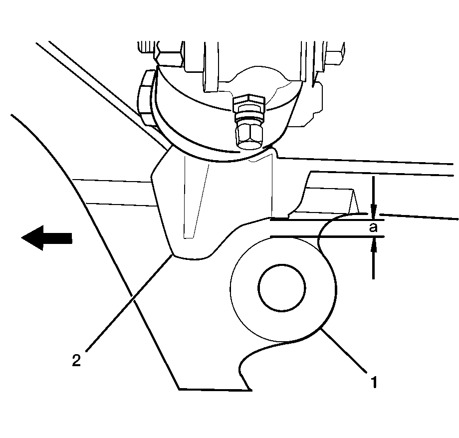
- Verify that the alignment of the jounce lower control arm (2) and stabilizer bushing link (1) of the factory control arm are within the specification. Add shims until the specification is correct.
- Install the outer shim and control arm brace, ensure that the pivot nut and brace slots are aligned.
- Install the 2 brace bolts (1) and tighten.
- Install the washer and pivot bolt (2).
- Verify the control arm pivots freely and that the final alignment is correct.
- Install the jounce shock absorber. Refer to Jounce Shock Absorber Replacement .
- Install the tire and wheel. Refer to Tire and Wheel Removal and Installation in Tires and Wheels in 2005 C/K Truck Service Manual.
- Lower the vehicle. Refer to Lifting and Jacking the Vehicle in General Information in 2005 C/K Truck Service Manual.


Specification A
5 mm ± 3.5 mm (0.20 in ±0.14 in).

Notice: Refer to Fastener Notice in the Preface section.
Tighten
Tighten bolts to 72 N·m (53 lb ft).
Tighten
Tighten bolt to 244 N·m (180 lb ft).
