For 1990-2009 cars only
Removal Procedure
- Raise the vehicle. Refer to Lifting and Jacking the Vehicle in General Information in 2005 C/K Truck Service Manual.
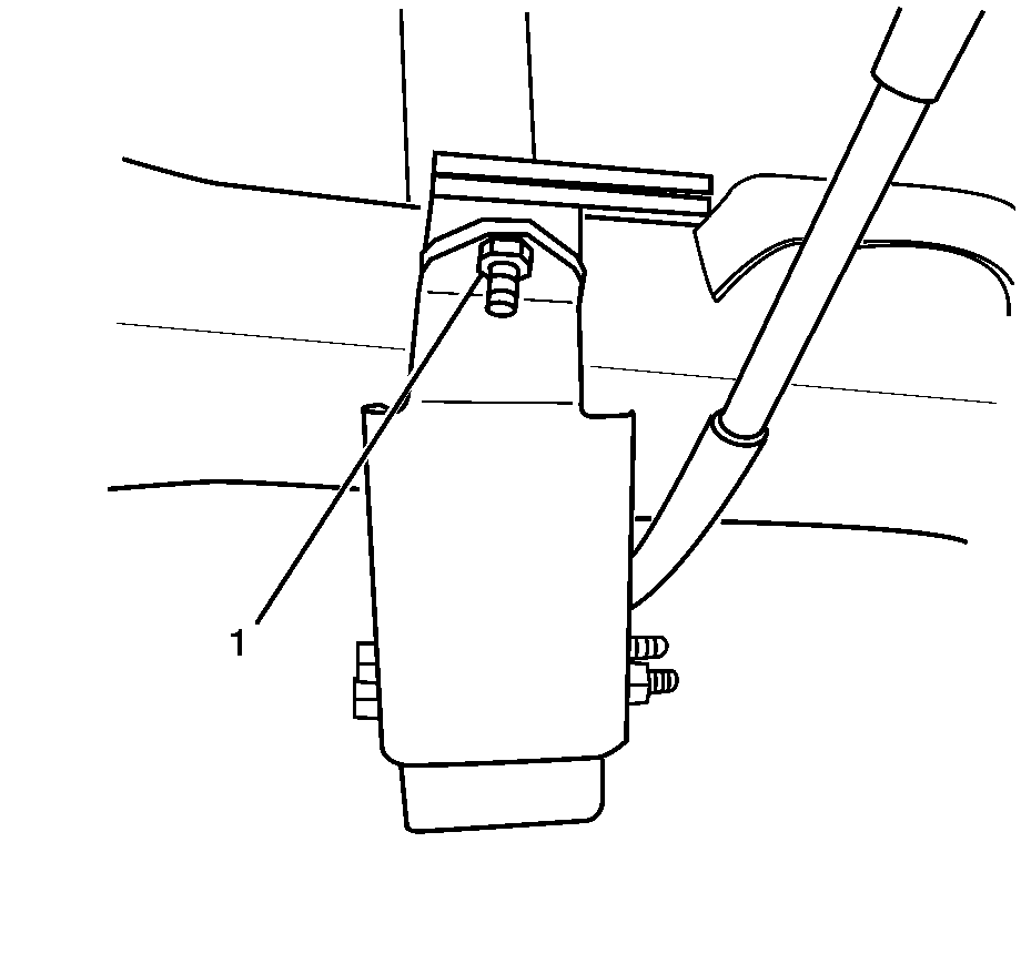
- Remove the top cover bolt (1).
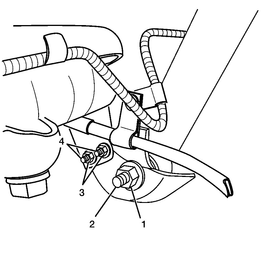
- Remove shock cover nuts (3) and bolts (4).
- Remove the lower shock nut (1) and bolt (2).
- Remove the shock cover pieces from the axle.
Caution: Refer to Vehicle Lifting Caution in the Preface section.
Installation Procedure
- Install the shock cover pieces on the axle. Ensure that the tab on the upper cover is in the slot of the lower cover.
- Install the lower shock bolt (2) and nut (1).
- Install bolts (4) and nuts (3) into the shock cover.
- Install the top shock cover bolt (1).
- Ensure that the contact pad of the jounce shock is aligned with the jounce shock.
- Lower the vehicle. Refer to Lifting and Jacking the Vehicle in General Information in 2005 C/K Truck Service Manual.
Notice: Refer to Fastener Notice in the Preface section.
Tighten
| • | Tighten lower shock bolt to 90 N·m (65 lb ft). |
| • | Tighten shock cover bolts to 35 N·m (26 lb ft). |
