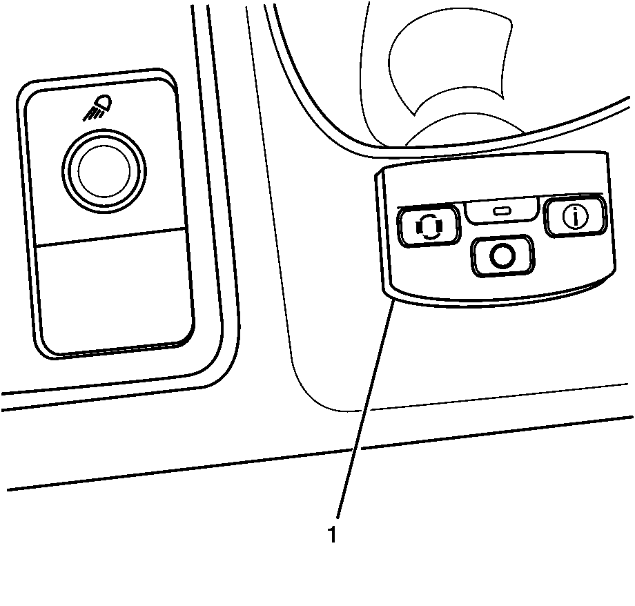
For 1990-2009 cars only
- Remove the I/P knee bolster panel. Refer to Knee Bolster Replacement in Instrument Panel, Gages and Console in 2005 C/K Truck Service Manual.
- Disconnect the switch panel cable from the receiver.
- Remove any wiring harness straps securing the cable to the vehicle.
- Pull the switch Panel off of the instrument panel cluster (IPC) trim plate bezel.
- Remove the switch panel (1), routing panel cable through the hole in the IPC bezel.

Note position of straps for reinstallation.
Note cable routing position for reinstallation.
Installation Procedure
- Apply Velcro strip to the back of the new switch panel.
- Install the switch panel (1), routing panel cable through the hole in the IPC bezel in the same locations as removed.
- Press the switch panel in place on the instrument panel cluster (IPC) trim plate bezel.
- Connect the switch panel cable to the receiver and secure with wiring harness straps in the same locations as removed.
- Install the I/P knee bolster panel. Refer to Knee Bolster Replacement in Instrument Panel, Gages and Console in 2005 C/K Truck Service Manual.
- Verify correct operation of the Tire Pressure Monitoring System.

