For 1990-2009 cars only
Removal Procedure
- Disconnect the battery cables. Refer to Battery Cable Disconnect and Connection in Engine Electrical.
- Remove the left fender upper brace.
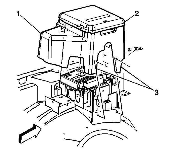
- Remove top cover (2).
- Remove the electrical center cover assembly (1) by lifting the cover outwards to clear the tabs (3).
- Remove the vehicle load disconnect switch (if equipped). Refer to Vehicle Load Disconnect Switch Replacement in Engine Electrical.
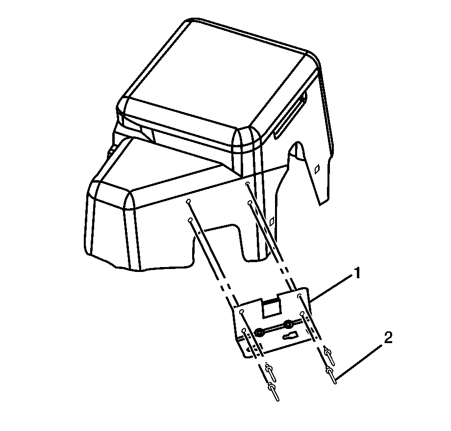
- Drill out the rivets (2) and remove bracket (1).
Caution: Refer to Battery Disconnect Caution in the Preface section.


Caution: Approved safety glasses and gloves should be worn when performing this procedure to reduce the chance of personal injury.
Installation Procedure
- Rivet the bracket (1) to the electrical center cover.
- Install the vehicle load disconnect switch (if equipped). Refer to Vehicle Load Disconnect Switch Replacement in Engine Electrical.
- Set the electrical center block in its resting position until the tabs (3) lock into place.
- Install the electrical center cover assembly (1).
- Install the top cover (2).
- Install the fender upper brace.
- Install the upper brace fasteners.
- Connect the battery cables. Refer to Battery Cable Disconnect and Connection in Engine Electrical.


Notice: Refer to Fastener Notice in the Preface section.
Tighten
Tighten the fasteners to 25 N·m (18 lb ft).
