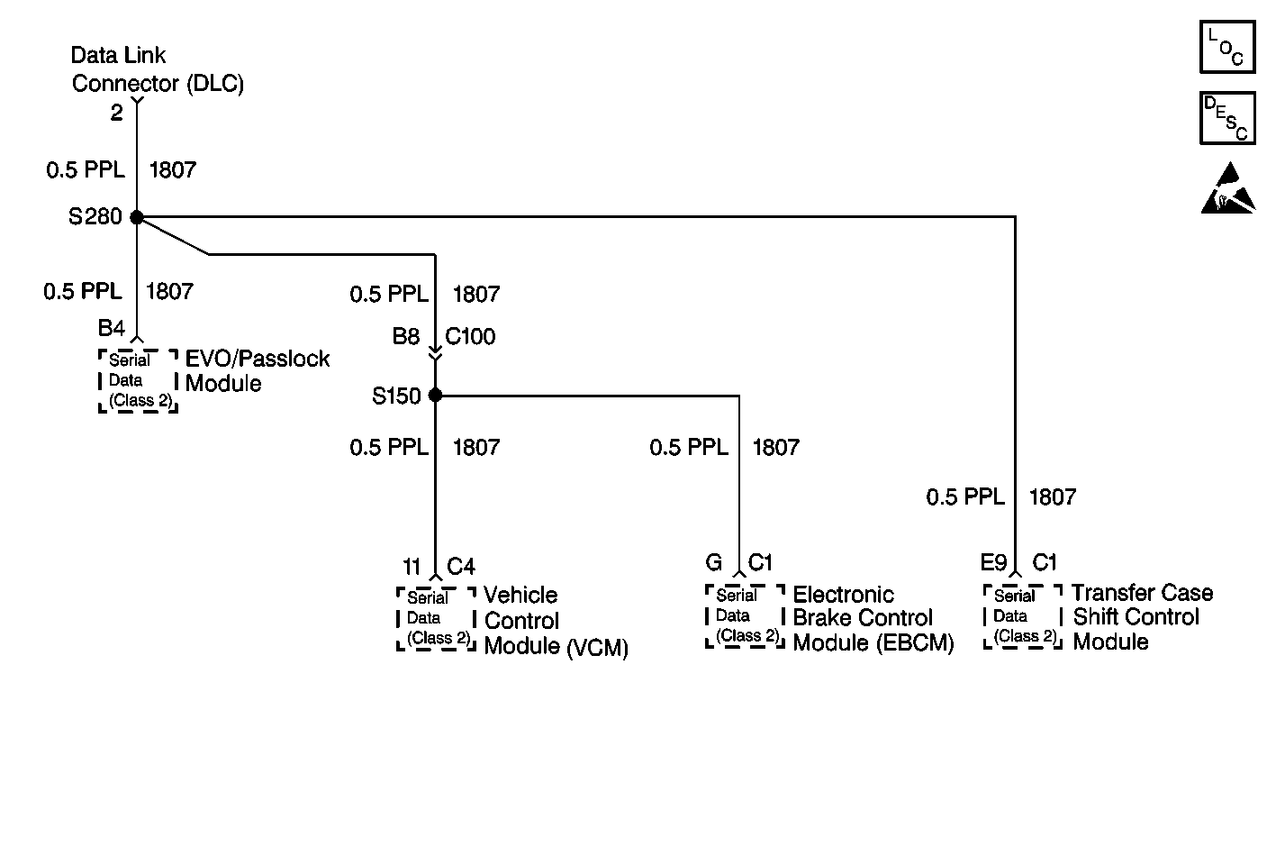
Circuit Description
The Class II Serial Data Circuit is used communicate between systems. Each system connected to the Class II Serial Data line is assigned its ownrecognition code (address). This code is used to identify which module or systems are communicating. The Node Alive or State of Health (SOH)messages are broadcast on the bus every 2 seconds. If a moduleis monitoring Node Alive messages for that module, it will reset its 5 secondtimer for that particular module. Any system that communicate properlywill also store the appropriate communication Diagnostic Trouble Codes(DTCs) thatare assigned to the system(s) it could not communicate with.
Conditions for Setting the DTC
All of the following conditions must be met:
| • | Ignition is active. |
| • | Communication between the Passlock™ Module and the VCM was present for at least 1 second, then lost for more than 5 seconds (usually due to intermittent connection). |
| • | The VCM has not received a valid state of health message from the Passlock™ Module. |
Action Taken When the DTC Sets
| • | Stores Diagnostic Trouble Code (DTC) U1016 in the Passlock™ Module memory. |
| • | If the ignition was OFF at the time, the vehicle will not start. |
| • | If the engine was running at the time, the vehicle will start again but the SECURITY indicator will remain illuminated.. |
Conditions for Clearing the MIL/DTC
| • | The Passlock™ Module continuously monitors the signal and moves the DTC from the current to history on the next ignition cycle when the condition causing the fault no longer exists. |
| • | All of the Passlock™ Module history codes will be cleared after 100 ignition cycles (from OFF to RUN) with no current codes active during the 100 ignition cycles. |
| • | Using a scan tool. |
Diagnostic Aids
| • | When the diagnostics direct you to take electrical measurement at the Wiring Harness Junction Blocks, refer to Wiring Systems for terminal assignments of the Wiring Harness Junction Blocks. |
| • | If the DTC is a history DTC, the problem may be intermittent. Try performing the tests shown while wiggling wiring and connectors, thiscan often cause the malfunction to appear. |
Test Description
-
The Data Link Communications System Check should be performed before any diagnostics are performed on the system.
-
This step is to determine if communications through CKT 1807 (PPL) are good.
-
This step is to determine if CKT 1807 (PPL) is at fault or if the problem is within theVehicle Control Module (VCM).
-
This step is to check CKT 1807 (PPL) and the Transfer Case Shift Control Module for circuit connections.
-
This step is to check CKT 1807 (PPL) and the EVO/Passlock™Module for circuit connections.
-
This step is to determine if CKT 1807 (PPL) is at fault or if the problem is within the Transfer Case Shift Control Module.
-
This step is to determine if CKT 1807 (PPL) is at fault or if the problem is within the EVO/Passlock™ Module.
Step | Action | Value(s) | Yes | No |
|---|---|---|---|---|
Was the Data Link Communications System Check performed? | -- | Go to Step 2 | ||
Establish communications with the Vehicle Control Module (VCM). Can communications be established? | -- | Go to Step 6 | Go to Step 3 | |
Is continuity present? | -- | Go to Step 4 | Go to Step 5 | |
4 | Replace the VCM. Refer to VCM Replacement/Programming (5.0L/5.7L) Is the repair complete? | -- | -- | |
5 | Locate and repair the open in CKT 1807 (PPL) between the VCM and the DLC. Refer to Wiring Repairs in Wiring Systems. Is the repair complete? | -- | -- | |
Establish communications with the Transfer Case Shift Control Module. Can communications be established? | -- | Go to Step 7 | Go to Step 8 | |
Establish communications with the EVO/Passlock™ Module. Can communications be established? | -- | Go to Step 11 | ||
Is continuity present? | -- | Go to Step 9 | Go to Step 10 | |
9 | Replace the Transfer Case Shift Control Module. Is the repair complete? | -- | -- | |
10 | Locate and repair the open or cause of resistance in CKT 1807 (PPL) between the Transfer CaseShift Control Module and splice S280.Refer to Wiring Repairs inWiring Systems. Is the repair complete? | -- | -- | |
Is continuity present? | -- | Go to Step 12 | Go to Step 13 | |
12 | Replace the EVO/Passlock™ Module. Is the repair complete? | -- | -- | |
13 | Locate and repair the open or cause of resistance in CKT 1807 (PPL) between the EVO/Passlock™ Module and splice S280. Refer to Wiring Repairs in Wiring Systems. Is the repair complete? | -- | -- |
