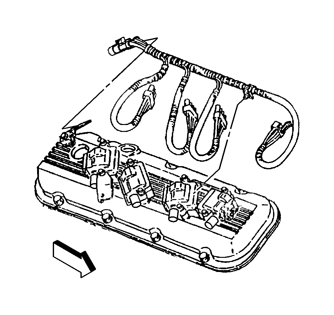
Valve Rocker Arm Cover Installation Left
- Install the ignition coils and ignition coils bolts to the valve rocker arm cover.
- If valve rocker arm cover gasket was removed from the valve rocker arm cover, install a NEW valve rocker arm cover gasket.
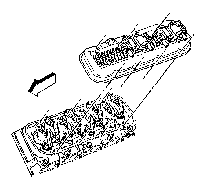
- Install the valve rocker arm cover with gasket.
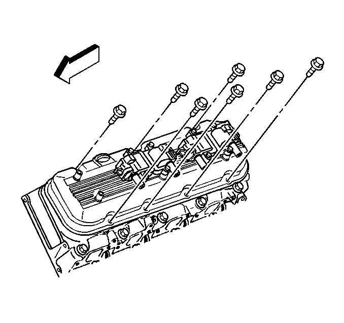
- Install the valve rocker arm cover bolts.
- Install the ignition coil wiring harness to the ignition coils.
- Install the ignition coil wiring harness to the valve rocker arm cover.
- Install the ignition coil wiring harness mounting bolts to the valve rocker arm cover.
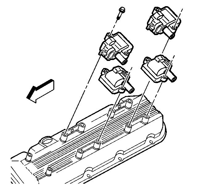
Notice: This bolt is a self-tapping bolt. If installing this bolt into a new component, installation of the bolt may be difficult. Ensure that the bolt is not over-torqued during the initial installation (thread cutting). Failure to limit torque can lead to bolt failure.
Notice: Use the correct fastener in the correct location. Replacement fasteners must be the correct part number for that application. Fasteners requiring replacement or fasteners requiring the use of thread locking compound or sealant are identified in the service procedure. Do not use paints, lubricants, or corrosion inhibitors on fasteners or fastener joint surfaces unless specified. These coatings affect fastener torque and joint clamping force and may damage the fastener. Use the correct tightening sequence and specifications when installing fasteners in order to avoid damage to parts and systems.
Tighten
Tighten the ignition coil bolts to 12 N·m (106 lb in).
Tighten
Tighten the valve rocker arm cover bolts to 12 N·m (106 lb in).
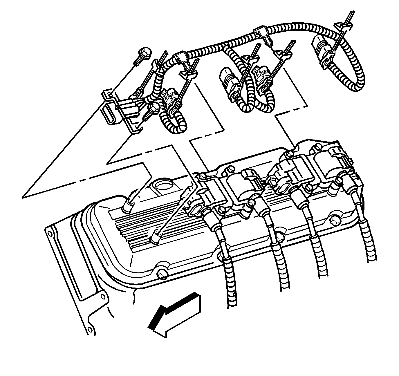
Notice: This bolt is a self-tapping bolt. If installing this bolt into a new component, installation of the bolt may be difficult. Ensure that the bolt is not over-torqued during the initial installation (thread cutting). Failure to limit torque can lead to bolt failure.
Tighten
Tighten the ignition coil wiring harness mounting bolts to 12 N·m
(106 lb in).
Valve Rocker Arm Cover Installation Right
- Install the ignition coils and ignition coils bolts (except the rear lower ignition coil bolt) to the valve rocker arm cover, if removed.
- Install the engine coolant temperature (ECT) sensor harness bracket and the ECT sensor harness bracket bolt to the valve rocker arm cover.
- Install the engine coolant temperature (ECT) sensor harness bracket bolt to the valve rocker arm cover.
- If valve rocker arm cover gasket was removed from the valve rocker arm cover, install a NEW valve rocker arm cover gasket.
- Install the valve rocker arm cover with gasket.
- Install the valve rocker arm cover bolts.
- Install the ECT sensor into the cylinder head.
- Connect the ECT sensor harness retainer into the ECT sensor harness bracket.
- Install the ignition coil wiring harness bracket to the valve rocker arm cover.
- Install the ignition coil wiring harness bracket bolt to the valve rocker arm cover.
- Install the ignition coil wiring harness to the ignition coils.
- Install the ignition coil wiring harness to the valve rocker arm cover.
- Install the ignition coil wiring harness to the ignition coil wiring harness bracket.
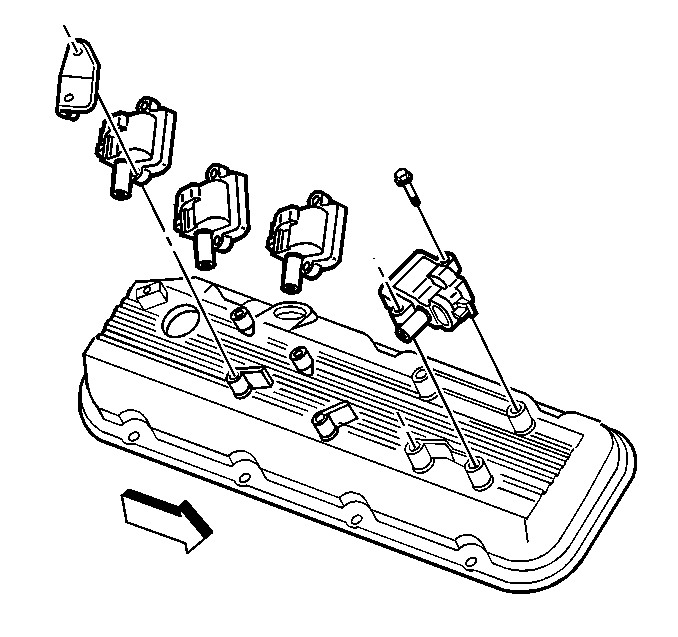
Notice: This bolt is a self-tapping bolt. If installing this bolt into a new component, installation of the bolt may be difficult. Ensure that the bolt is not over-torqued during the initial installation (thread cutting). Failure to limit torque can lead to bolt failure.
Notice: Use the correct fastener in the correct location. Replacement fasteners must be the correct part number for that application. Fasteners requiring replacement or fasteners requiring the use of thread locking compound or sealant are identified in the service procedure. Do not use paints, lubricants, or corrosion inhibitors on fasteners or fastener joint surfaces unless specified. These coatings affect fastener torque and joint clamping force and may damage the fastener. Use the correct tightening sequence and specifications when installing fasteners in order to avoid damage to parts and systems.
Tighten
Tighten the ignition coil bolts to 12 N·m (106 lb in).
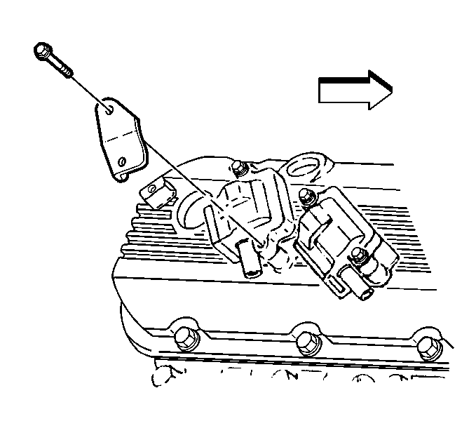
Notice: This bolt is a self-tapping bolt. If installing this bolt into a new component, installation of the bolt may be difficult. Ensure that the bolt is not over-torqued during the initial installation (thread cutting). Failure to limit torque can lead to bolt failure.
Important: Ensure the engine coolant temperature (ECT) sensor harness bracket is positioned away from the ignition coil. Incorrect positioning will prevent installation of the the spark plug wire onto the ignition coil.
Tighten
Tighten the ECT sensor harness bracket bolt to 12 N·m (106 lb in).
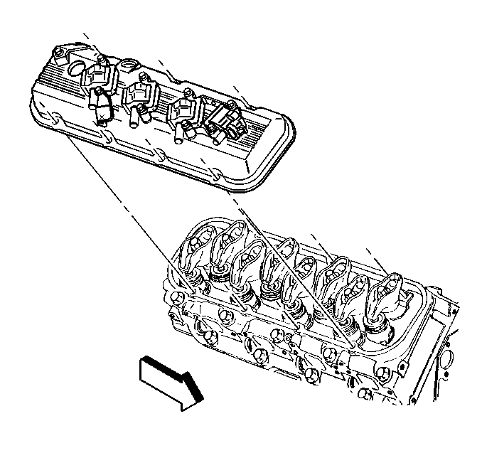
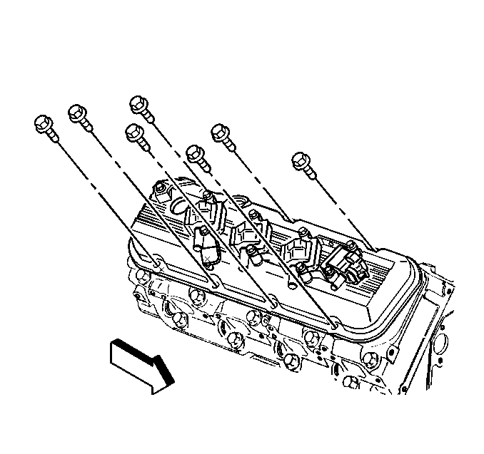
Tighten
Tighten the valve rocker arm cover bolts to 12 N·m (106 lb in).
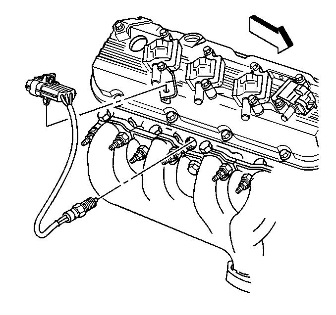
Tighten
Tighten the ECT sensor to 20 N·m (15 lb ft).
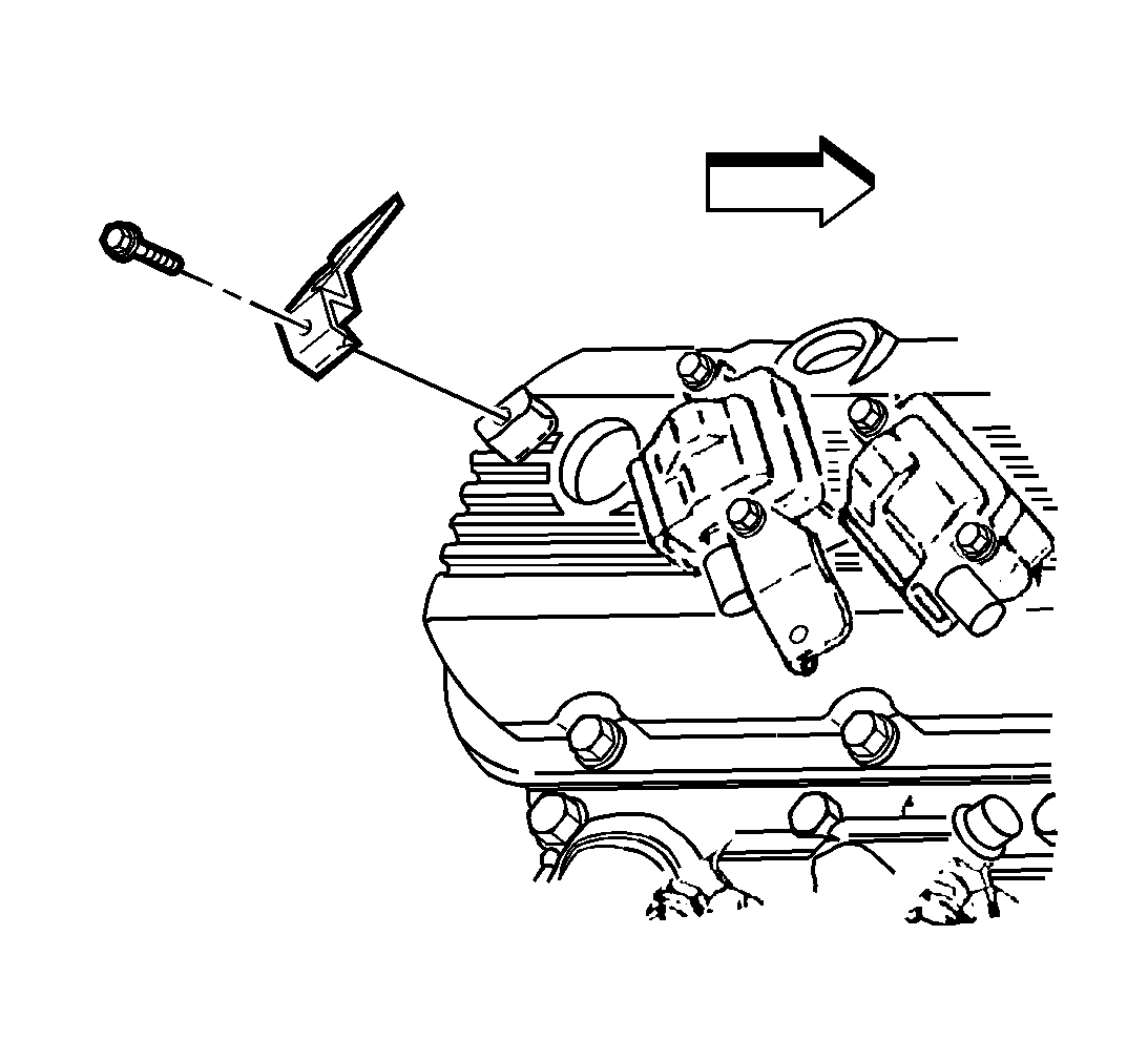
Notice: This bolt is a self-tapping bolt. If installing this bolt into a new component, installation of the bolt may be difficult. Ensure that the bolt is not over-torqued during the initial installation (thread cutting). Failure to limit torque can lead to bolt failure.
Tighten
Tighten the ignition coil wiring harness bracket bolt to 12 N·m
(106 lb in).
