Tools Required
| • | J 22102 Front Cover Oil Seal Installer |
| • | J 7872 Magnetic Base Dial Indicator Set |
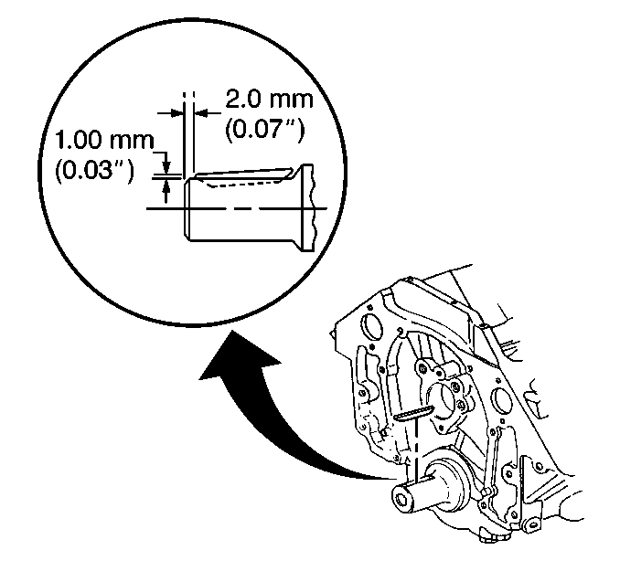
- Properly install the crankshaft key into the crankshaft keyway, if removed.
- Install and align the keyway of the crankshaft sprocket with the crankshaft key.
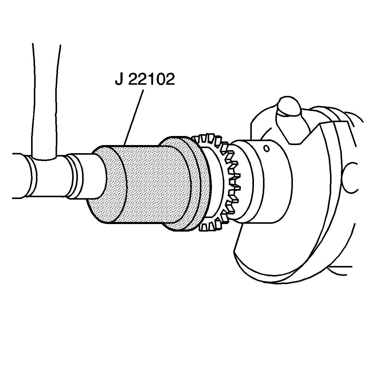
- Install the crankshaft sprocket using the J 22102 .
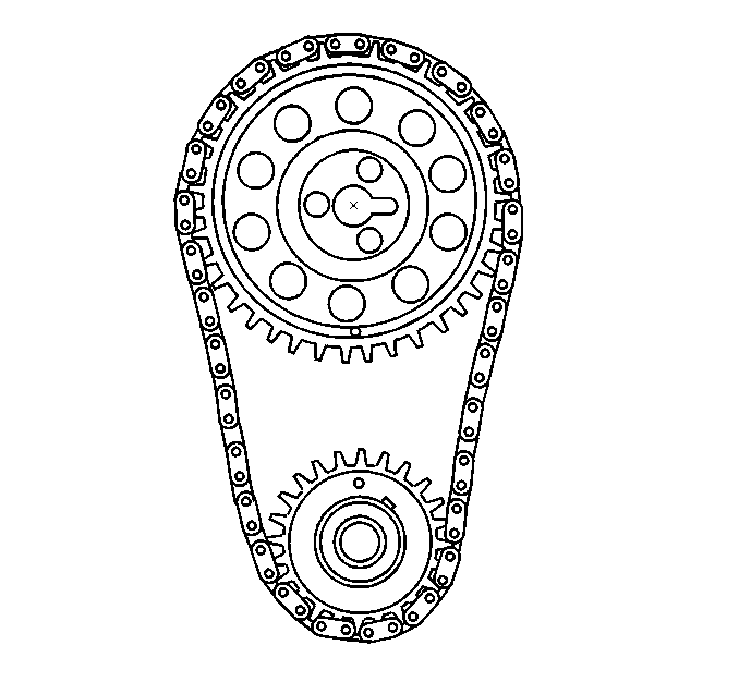
- Rotate the crankshaft until the crankshaft sprocket alignment mark is in the 12 o'clock position.
- Rotate the camshaft until the camshaft alignment pin is in the 3 o'clock position.
- Install the camshaft sprocket and timing chain.
- Look to ensure that the crankshaft sprocket mark is aligned at the 12 o'clock position and the camshaft sprocket mark is aligned at the 6 o'clock position.
- Install camshaft sprocket bolts.
- Inspect the camshaft sprocket-to-camshaft retainer clearance to ensure that there is no binding condition using the J 7872 . The end play should measure 0.050-0.275 mm (0.002-0.011 in).
- Install and align the keyway of the crankshaft position reluctor ring with the crankshaft key.
- Use the J 22102 in order to install the crankshaft position reluctor ring onto the crankshaft until the ring is completely seated against the crankshaft sprocket.
Important: If the sprocket(s) are being replaced, replace both sprockets to ensure that timing chain centerline alignment is maintained.
Important: The crankshaft sprocket is installed with the timing mark visible from the front and the chamfer on the crankshaft sprocket bore installed towards the crankshaft/engine block.
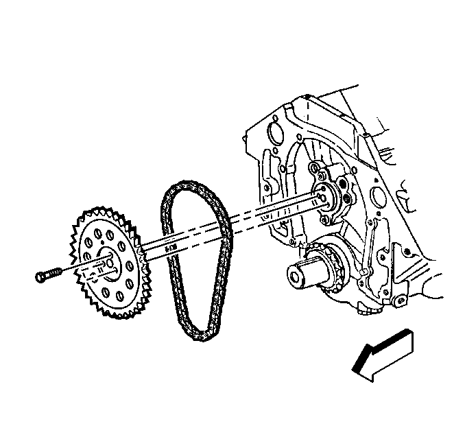
Notice: The sprocket teeth must mesh with the timing chain in order to prevent damage to the camshaft retainer.
Notice: Do not hammer the camshaft sprocket onto the camshaft. To do so may dislodge the rear camshaft plug and damage the camshaft.
Important: Ensure the camshaft alignment pin is engaged with the camshaft sprocket slot.
Important: Install the camshaft sprocket with the alignment mark in the 6 o'clock position.
Notice: Use the correct fastener in the correct location. Replacement fasteners must be the correct part number for that application. Fasteners requiring replacement or fasteners requiring the use of thread locking compound or sealant are identified in the service procedure. Do not use paints, lubricants, or corrosion inhibitors on fasteners or fastener joint surfaces unless specified. These coatings affect fastener torque and joint clamping force and may damage the fastener. Use the correct tightening sequence and specifications when installing fasteners in order to avoid damage to parts and systems.
Tighten
Tighten the camshaft sprocket bolts to 30 N·m (22 lb ft).
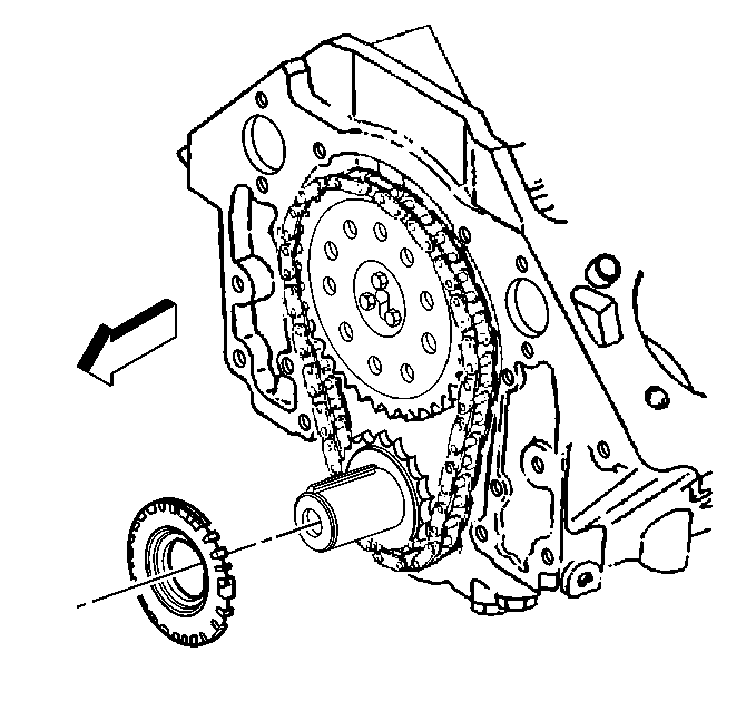
Important: If the crankshaft sensor reluctor ring has been removed from the crankshaft, a new crankshaft sensor reluctor ring must be installed.
Important: Ensure the J 22102 contacts the crankshaft balancer contact area of the crankshaft position reluctor ring in order to prevent bending or damage to the crankshaft position reluctor ring teeth.
Important: It should be necessary to apply only light force in order to install the crankshaft position reluctor ring with the J 22102 .
