- Align the timing mark on the front cover with the TDC mark on the balancer.
- Align the spot mark on the camshaft position sensor gear with the paint mark on the camshaft position sensor lower base.
- Remove the cover from the camshaft position sensor.
- Use a long flat blade screwdriver to rotate the oil pump driveshaft to engage the tang of the camshaft position sensor drive gear.
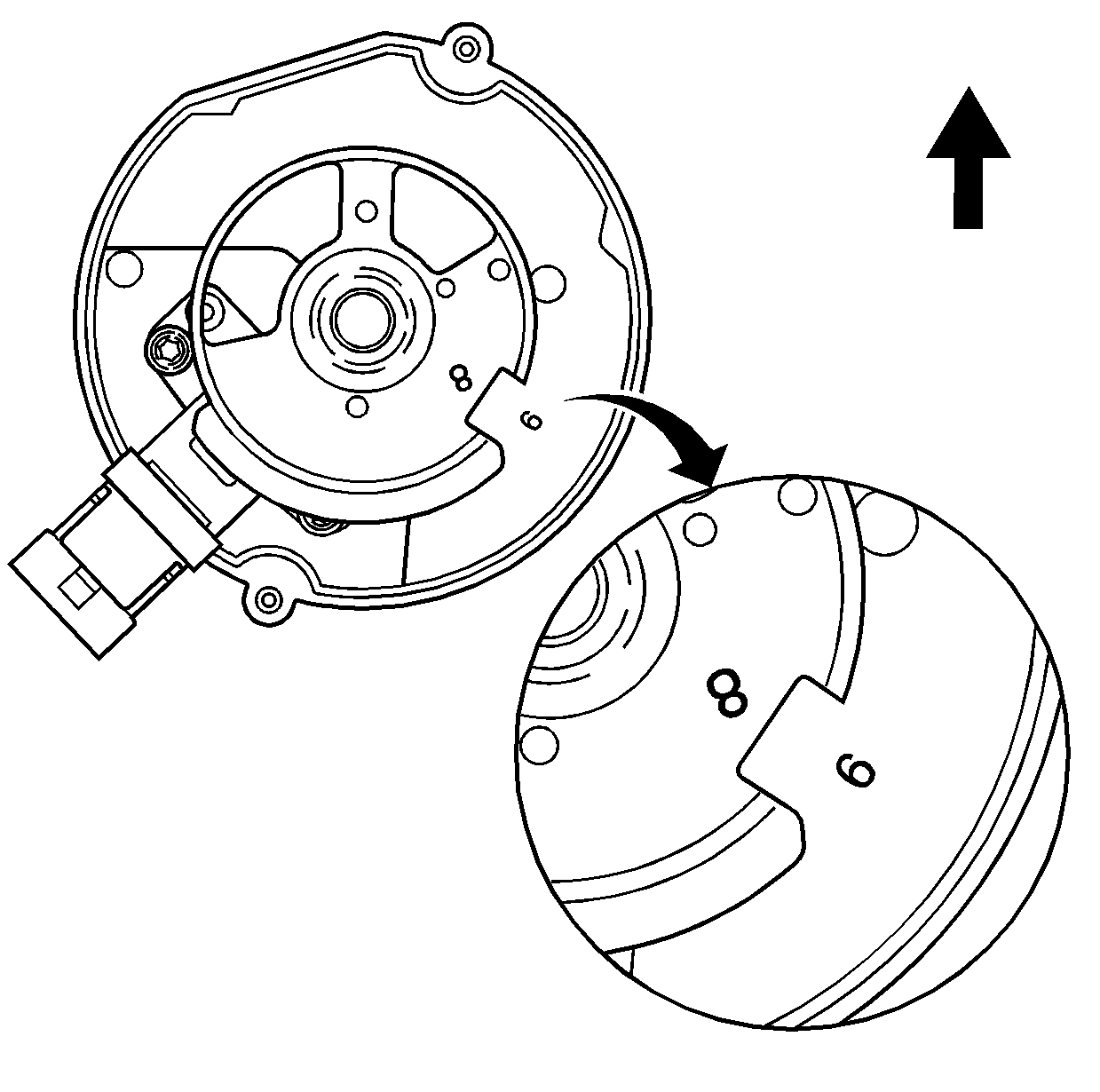
- With the camshaft position sensor in proper alignment, the reluctor wheel cutout should line up with the pointer on the camshaft position sensor housing.
- Without holding the reluctor wheel, guide the camshaft position sensor into the hole in the intake manifold until the camshaft position sensor is seated. The reluctor wheel will turn clockwise as the camshaft position sensor is lowered into the engine.
- When properly installed, the reluctor wheel cutout should be in approximately the four o'clock position and should line up with the stamped number "9" on the camshaft position sensor housing.
- Install the camshaft position sensor hold down clamp and bolt.
- Install the camshaft position sensor cover and screws. Do not overtighten.
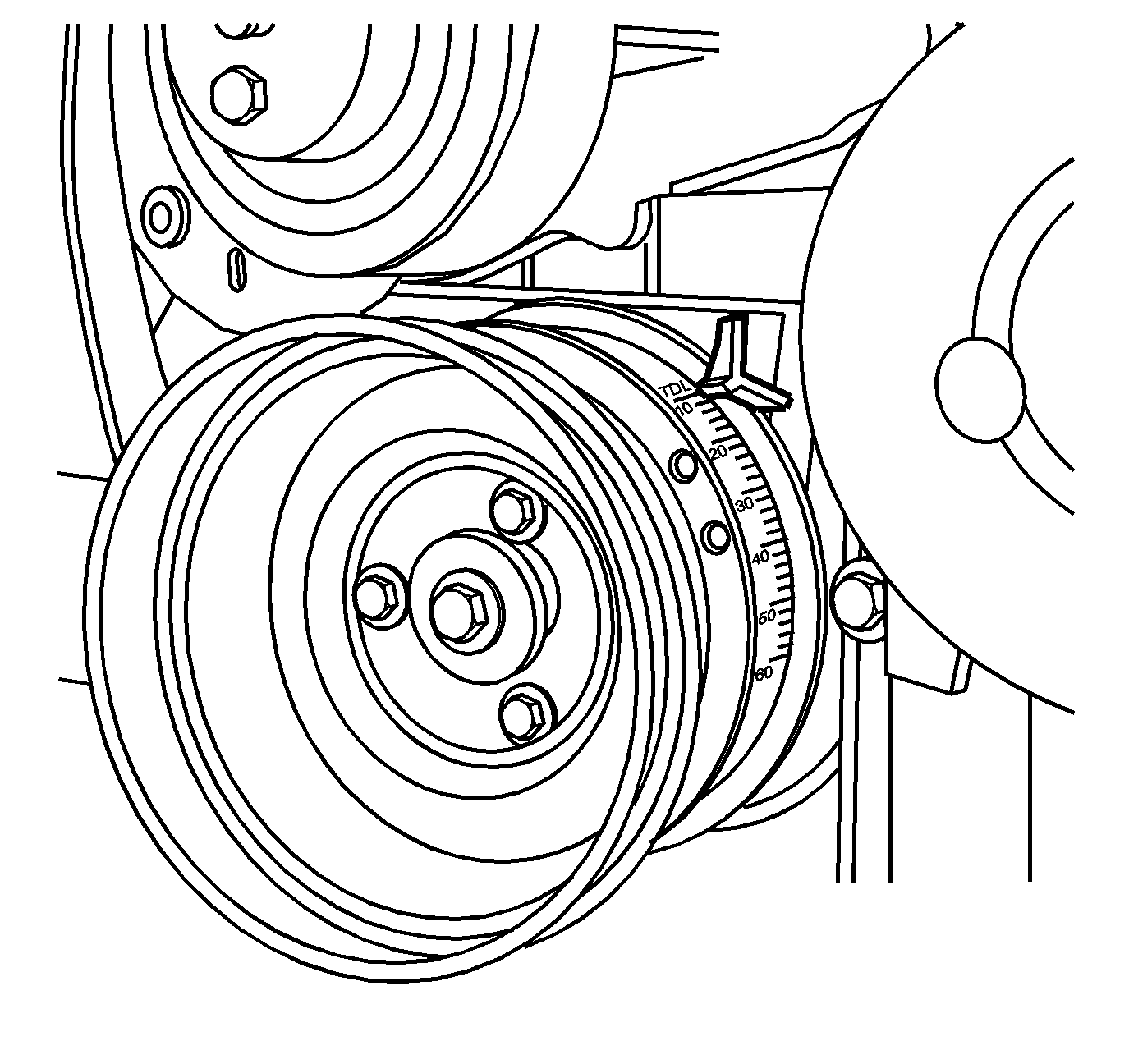
Important: The number one cylinder intake and exhaust valves must be in the closed position.
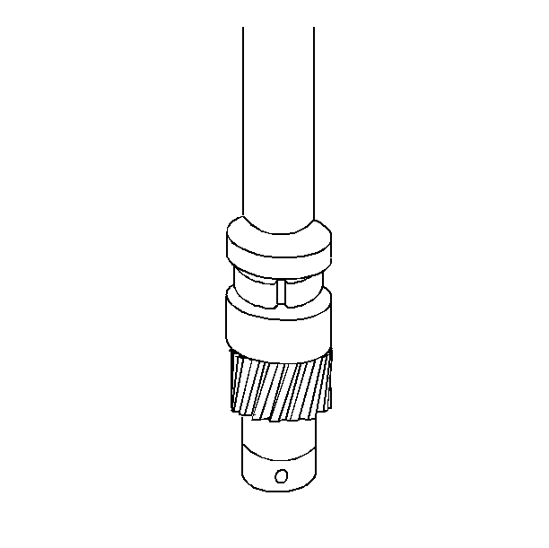
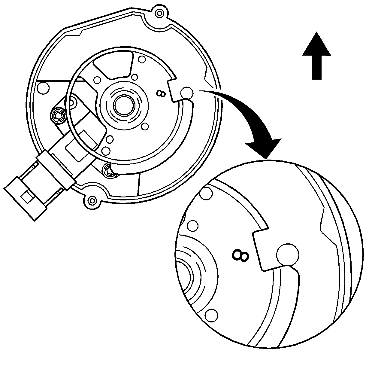
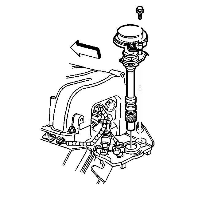
Important: The camshaft position sensor must be completely seated to allow proper engagement of the camshaft position sensor drive gear tang to the oil pump driveshaft. Repeat the installation procedure if the proper alignment is not obtained.
Notice: Use the correct fastener in the correct location. Replacement fasteners must be the correct part number for that application. Fasteners requiring replacement or fasteners requiring the use of thread locking compound or sealant are identified in the service procedure. Do not use paints, lubricants, or corrosion inhibitors on fasteners or fastener joint surfaces unless specified. These coatings affect fastener torque and joint clamping force and may damage the fastener. Use the correct tightening sequence and specifications when installing fasteners in order to avoid damage to parts and systems.
Important: The camshaft position sensor hold down clamp must properly align with the mounting hole in the intake manifold. Repeat the installation procedure if the proper alignment is not obtained.
Tighten
Tighten the bolt to 33 N·m (24 lb ft).
Tighten
Tighten the screws to 5 N·m (40 lb in).
