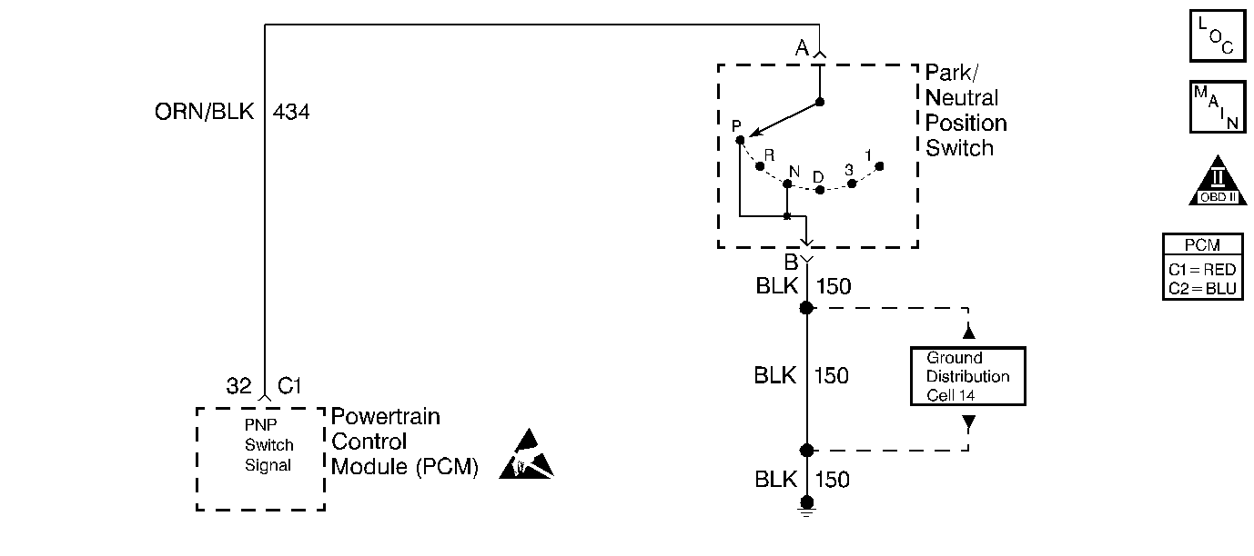
Circuit Description
The Park Neutral Position (PNP) switch contacts are closed to ground when the transmission gear selector is placed in the Park and the Neutral positions, and open in Reverse and the Drive positions.
The Powertrain Control Module (PCM) supplies ignition voltage, through a current limiting resistor, to the Park/Neutral signal circuit and senses a closed PNP switch when the voltage on the Park/Neutral signal circuit drops to less than 1 volt.
The PCM uses this signal as one of the inputs in order to control the following:
| • | Throttle angle at idle. |
| • | Fuel delivery at idle. |
| • | Inhibit the starter relay operation when the transmission is in gear(neutral start). |
Diagnostic Aids
Important: The PCM will not energize the starter relay if the park/neutral signal circuit to the PCM is open or if the PNP switch is disconnected.
When the ignition switch is turned to the START(crank) position and the Park/Neutral signal circuit indicates Park/Neutral (grounded), the PCM will energize the starter relay even if the transmission gear selector is in a Drive or Reverse range.If the neutral signal circuit indicates neutral (grounded), while in drive range, the EGR would be inoperative, resulting in possible detonation.
If the neutral signal circuit always indicates Reverse/Drive (open), a drop in the idle may exist when the gear selector is moved into Drive or Reverse range.
Test Description
The number(s) below refer to the step number(s) on the diagnostic table.
-
Checks for a closed switch to ground in the Park and the Neutral position.
-
Be sure scan indicates both positions, even while wiggling shifter in order to test for an intermittent switch in the Reverse and all of the Drive positions of the transmission gear selector.
-
This step determines if the problem is in the switch or the circuits.
Step | Action | Value(s) | Yes | No |
|---|---|---|---|---|
1 | Did you perform the Powertrain On-Board Diagnostic (OBD) System Check? | -- | ||
Does the scan tool indicate the transmission is in P/N? | -- | |||
Does the scan tool indicate the transmission is in Reverse/Drive? | -- | System OK | ||
4 | Disconnect the PNP switch electrical connector. Refer to Transmission/Automatic Transmission-Allison/ Neutral Start Switch Replacement Does the scan tool indicate Reverse/Drive? | -- | ||
Does the scan tool indicate the transmission is in neutral? | -- | |||
6 |
Was a problem found and repaired? | -- | ||
7 | Replace the Park/Neutral switch.Refer to Transmission/Automatic Transmission-Allison/ Neutral Start Switch Replacement Is the action complete? | -- | -- | |
8 | Jumper the Park/Neutral signal circuit at the harness connector terminal to battery ground. Does the scan tool indicate the transmission is in Park/Neutral? | -- | ||
9 | Repair the open ground circuit. Is the action complete? | -- | -- | |
10 |
Was a problem found? | -- | ||
11 | Check for poor connection/terminal tension at the PCM harness connector. Refer toBody and accessories/Wiring Systems for the proper procedure. Was a problem found and repaired? | -- | ||
12 |
Was a problem found And repaired? | -- | ||
13 | Replace the PCM. Refer to Powertrain Control Module Replacement Is the action complete? | -- | -- | |
14 | Operate the vehicle within the conditions under which the original symptom was noted. Does the system now operate properly? | -- | System OK | Refer to Diagnostic Aids |
