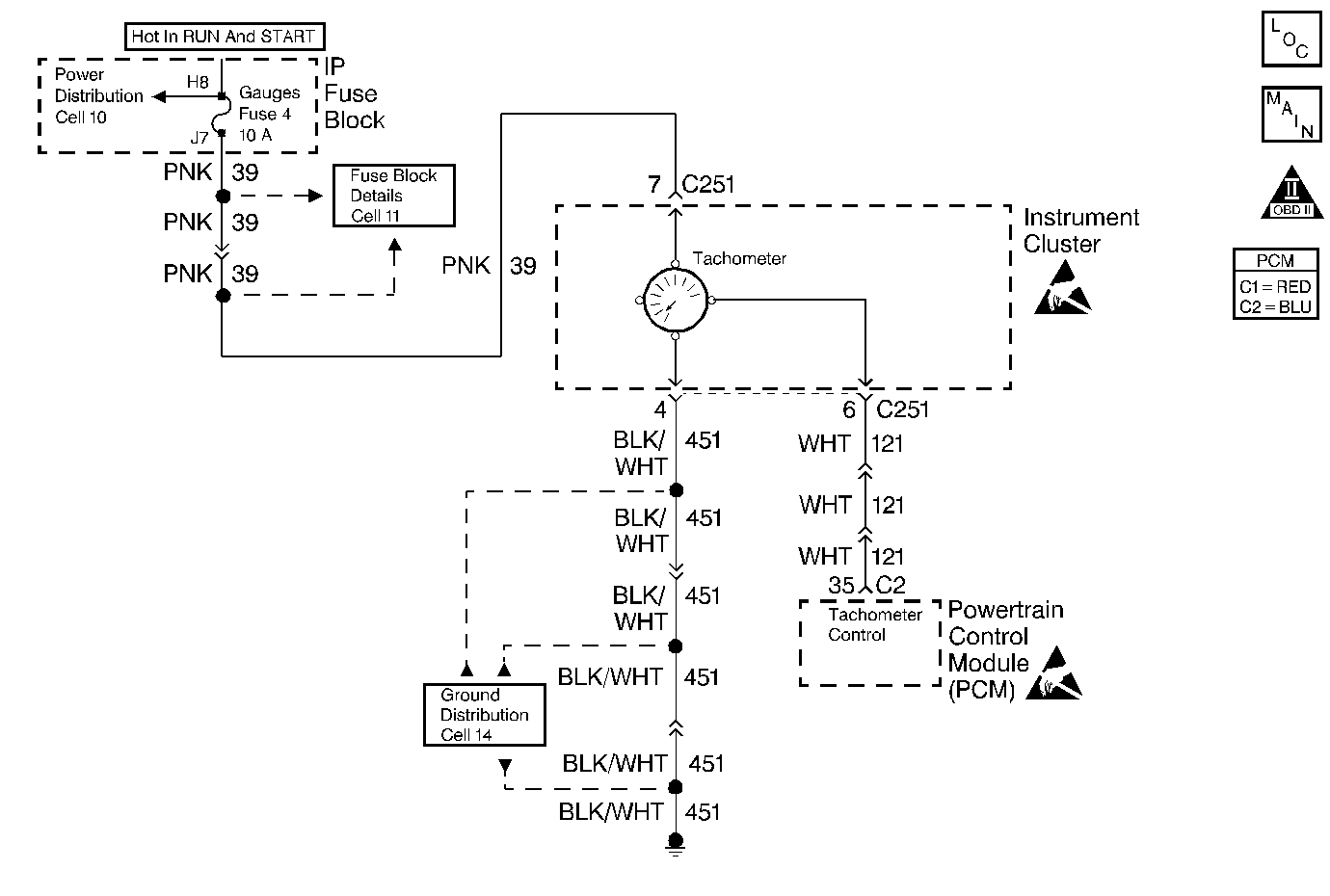
Circuit Description
The tachometer supplies ignition positive voltage to the PCM by way of the tachometer control circuit. The Crankshaft Position (CKP) sensor signal indicates to the PCM that the crankshaft is rotating. The PCM controls the tachometer by momentarily grounding the tachometer control circuit and causing the voltage to pulse at the rate of two times per crank shaft revolution. The solid state circuits of the tachometer convert the voltage pulses in order to drive the tachometer pointer and display engine speed in RPM.
Diagnostic Aids
Check for the following conditions:
| • | Poor connection at the PCM or instrument cluster. Inspect harness connectors for backed out terminals, improper mating, broken locks, improperly formed or damaged terminals, and poor terminal to wire connection. |
| • | Damaged harness. Inspect the wiring harness for damage. If the harness appears to be OK, disconnect the PCM, turn the ignition ON and observe a voltmeter connected to the tachometer control circuit at the PCM harness connector while moving connectors and wiring harnesses related to the tachometer control circuit. A change in voltage will indicate the location of the fault. |
Test Description
Number(s) below refer to the step number(s) on the diagnostic table.
-
The tachometer diagnosic table will direct you back to this diagnostic table if a problem is not found elsewhere in the tachometer circuitry.
-
This test may help identify a Crankshaft Position (CKP) sensor problem by indicating a CKP DTC.
-
Normally, ignition positive voltage is present on the tachometer control circuit with the PCM disconnected and the ignition turned ON.
Step | Action | Value(s) | Yes | No |
|---|---|---|---|---|
1 | Did you perform the tachometer diagnosis.? | -- | Go to Tachometer Inaccurate | |
2 | Did you perform the Powertrain On-Board Diagnostic (OBD) System Check? | -- | ||
3 |
Important: Reconnect any components that where disconnected in any previous diagnostic procedures.
Is the test lamp ON? | Go to step 5 | Go to step 4 | |
4 |
Was a problem found and repaired? | -- | ||
5 |
| -- | ||
6 | Replace the PCM. Important: Replacement PCM must be programmed. Refer to Powertrain Control Module Replacement Is the action complete? | -- | -- | |
7 |
Does the tachometer operate properly? | -- | System OK | Go to Tachometer Inaccurate |
