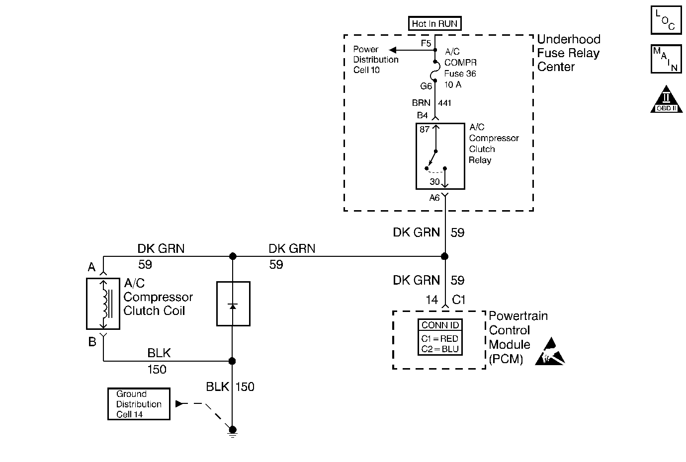
Circuit Description

When the A/C control switch is turned ON and the A/C compressor relay is energized, voltage should be present at both the A/C compressor clutch and the A/C clutch status circuit at the PCM. The PCM does not control the A/C compressor clutch.The PCM monitors the operation of the A/C compressor clutch through the A/C Status circuit. The PCM uses this information in order to compensate for the engine load changes, caused by the A/C system, by adjusting the ignition timing and the throttle angle.
Test Description
The numbers below refer to the step numbers on the diagnostic table.
Important: In order to properly diagnose the A/C system, the outside temperature must be above 16°C (60°F).
-
This step checks the operation of the A/C compressor clutch.
-
This verifies that the A/C Status circuit has been repaired and that the PCM has the ability to determine that the A/C compressor clutch is ingaged.
Step | Action | Value(s) | Yes | No |
|---|---|---|---|---|
1 | Did you perform the Powertrain On-Board Diagnostic (OBD) System Check? | -- | ||
Perform the A/C Functional Check. Refer to HVAC/HVAC Systems with A/C- Manual Does the A/C clutch operate properly? | -- | Go to HVAC/HVAC Systems with A/C- Manual | ||
3 |
Does the scan tool indicate A/C Status as ON? | System OK | ||
4 |
Does the test lamp illuminate? | |||
5 | Check for poor connection/terminal tension at the PCM connector. Refer to Body and Accessories/Wiring Systems for the proper procedure. Was a problem found and repaired? | |||
6 | Repair the open A/C clutch status circuit from the splice to the PCM. Is the action complete? | -- | -- | |
7 |
Important:: Program the replacement PCM. Refer to Powertrain Control Module Replacement . Replace the PCM. Is the action complete? | -- | -- | |
Does the scan tool indicate A/C Status as ON? | System OK |
