Power Steering Fluid Reservoir Replacement - Off Vehicle Remote
Removal Procedure
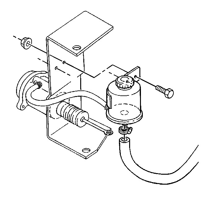
- Place a container under the power steering reservoir hoses.
- Clean the surfaces of the power steering reservoir hoses.
- Disconnect the power steering reservoir hoses.
- Allow the reservoir to drain.
- Remove the reservoir.
Notice: Avoid contaminating the power steering system. Cap open hoses and ports to prevent dirt and debris from entering system. Contaminated power steering fluid and dirt can cause early parts failure.
Important: Cap the hoses to prevent dirt from entering the system.
Installation Procedure
- Position the reservoir on the vehicle dash and toe panel.
- Install the following components:
- Fill the system with new power steering fluid.
- Bleed the system. Refer to Power Steering System Bleeding .

Notice: Use the correct fastener in the correct location. Replacement fasteners must be the correct part number for that application. Fasteners requiring replacement or fasteners requiring the use of thread locking compound or sealant are identified in the service procedure. Do not use paints, lubricants, or corrosion inhibitors on fasteners or fastener joint surfaces unless specified. These coatings affect fastener torque and joint clamping force and may damage the fastener. Use the correct tightening sequence and specifications when installing fasteners in order to avoid damage to parts and systems.
| • | The bracket bolts |
| • | The hose clamps |
| • | The hose sleeve |
| • | The hoses |
Tighten
| • | Tighten the reservoir mounting nut to 27 N·m (20 lb ft). |
| • | Tighten the hose clamp to 3 N·m (27 lb in). |
Power Steering Fluid Reservoir Replacement - Off Vehicle Pump
Disassembly Procedure
- Drain the power steering fluid from the power steering pump.
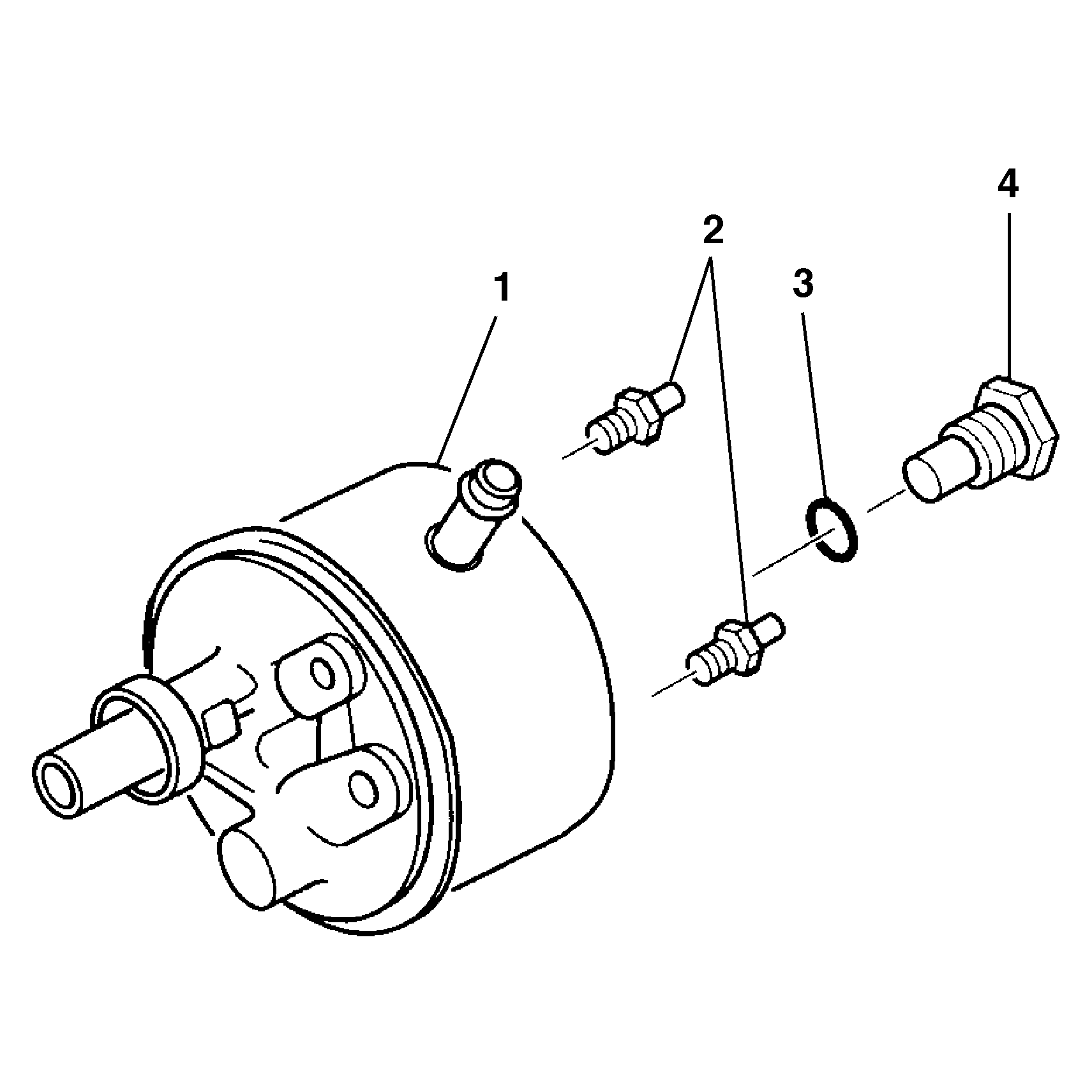
- Remove the pump mounting studs (2).
- Remove the connector and fitting assembly (4).
- Remove the O-ring seal (3).
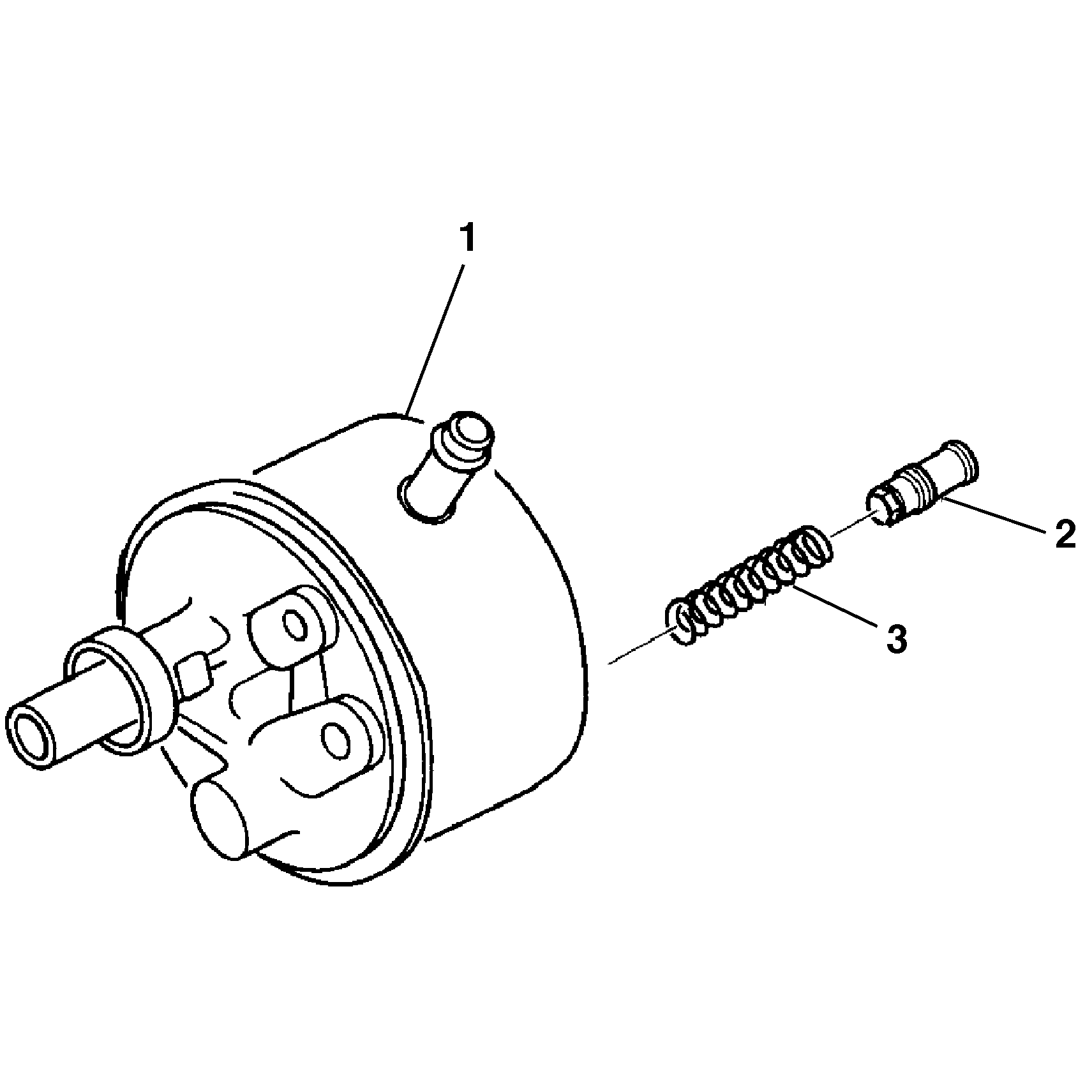
- If replacement is required, remove the control valve assembly (2) and the flow control spring (3) from the pump housing assembly (1).
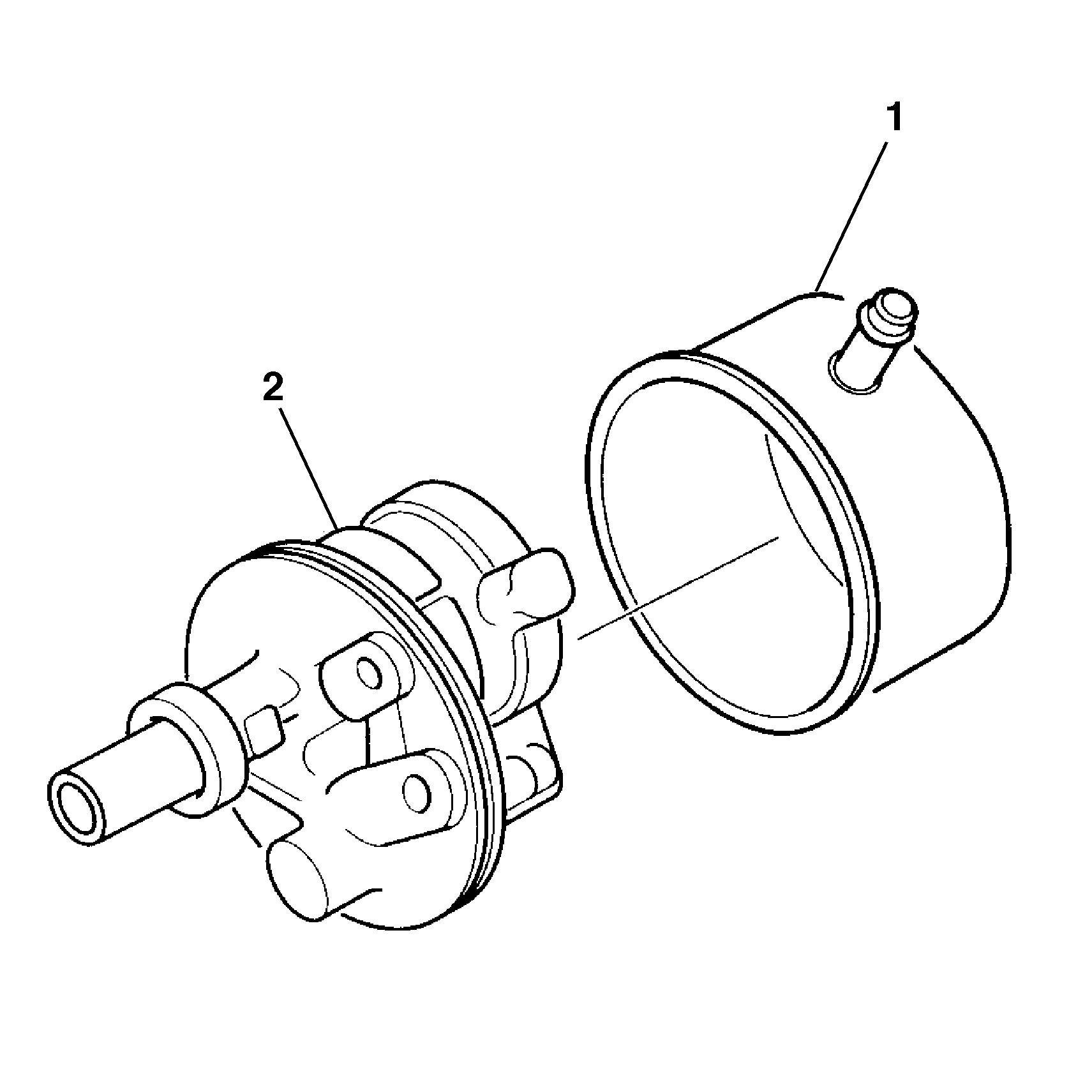
- Remove the reservoir assembly (1) from the pump housing assembly (2).
- Remove the O-ring seals (1) (7) (8).
- Remove the magnet (3).
- Clean the magnet (3).
- Inspect the welch plug in the power steering pump housing (2). Do not remove. If the welch plug is deformed or dislodged, replace the power steering pump housing (2).
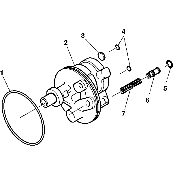
Assembly Procedure
- Lubricate the O-ring seals (1) (7) (8) with power steering fluid.
- Install the flow control spring (4) to the pump housing assembly (2).
- Install the control valve assembly (9) to the flow control spring (4).
- Install the O-ring seals (1) (7) (8) to the pump housing assembly.
- Install the magnet (3) to the pump housing assembly (2).
- Connect the reservoir assembly (1) to the pump housing assembly (2).
- Install the O-ring seal.
- Install the connector and fitting assembly (4) to the pump housing (1).
- See
Notice: Use the correct fastener in the correct location. Replacement fasteners must be the correct part number for that application. Fasteners requiring replacement or fasteners requiring the use of thread locking compound or sealant are identified in the service procedure. Do not use paints, lubricants, or corrosion inhibitors on fasteners or fastener joint surfaces unless specified. These coatings affect fastener torque and joint clamping force and may damage the fastener. Use the correct tightening sequence and specifications when installing fasteners in order to avoid damage to parts and systems.
- Install the pump mounting studs (2) to the pump housing (1).

Important: Use new O-ring seals when assembling the power steering pump assembly.


Tighten
Tighten the pump mounting studs (2) to 35-80 N·m
(29-59 lb ft).
Tighten
Tighten the connector and fitting assembly (4) to 75 N·m
(55 lb ft).
