Steering Column Replacement Process
Removal Procedure
Notice: Once the steering column is removed from the vehicle, the column is
extremely susceptible to damage. Dropping the column assembly on the end could
collapse the steering shaft or loosen the plastic injections, which maintain
column rigidity. Leaning on the column assembly could cause the jacket to
bend or deform. Any of the above damage could impair the columns collapsible
design. Do NOT hammer on the end of the shaft, because hammering could loosen
the plastic injections, which maintain column rigidity. If you need to remove
the steering wheel, refer to the Steering Wheel Replacement procedure in this
section.
Important: The front wheels of the vehicle must be maintained in the straight ahead
position and the steering column must be in the LOCK position before disconnecting
the steering column or intermediate shaft. Failure to follow these
procedures will cause improper alignment of some components during
installation.
- Remove the steering wheel. Refer to
Steering Wheel Replacement
.
- Remove the ignition lock cylinder. Refer toIgnition and Key Alarm Switch Assembly - Disassemble - Off Vehicle
.
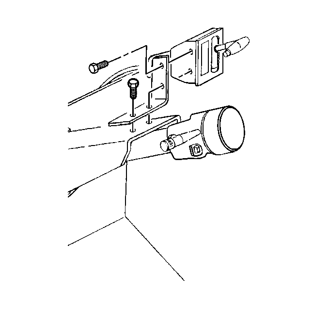
- Disconnect the transmission
control/range selector assembly bracket from the top of the upper steering
column support.
- Remove the parking brake auto apply switch connector, if damaged
or malfunctioning. Refer to
Park Brake Pull Switch Replacement
in Park Brake.
- Remove the parking brake pull button switch connector from its
bracket on the upper steering column support. Refer to
Park Brake Pull Switch Replacement
in Park Brake.
- Remove the steering wheel. Refer to
Steering Wheel Replacement
.
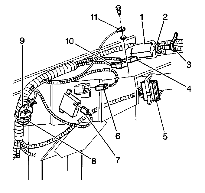
- Remove the instrument
panel harness connectors and the ground wire, including:
| • | the strap (3) and the tape (2). |
| • | the instrument panel wiring harness extension connector (4). |
| • | the steering column harness connector (5). |
| • | the daytime running lamp connector (6). |
| • | the calibrator connector (7). |
| • | the DRL module connector (8) and bag (9). |
| • | the extension wiring harness connector (10). |
| • | the ground harness terminal (11). |
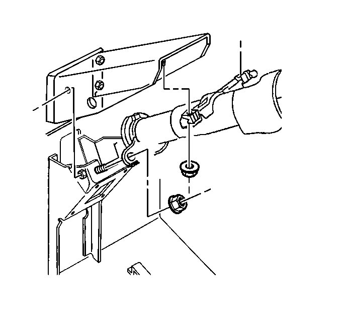
- Remove the steering column
mounting bracket nuts to the upper steering support studs.
- Remove the steering column mounting bracket nuts to the floor
and dash support panel assembly studs.
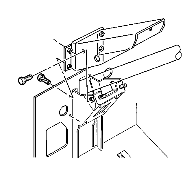
- Remove the upper steering
column support bolts.
- Remove the upper steering column support.
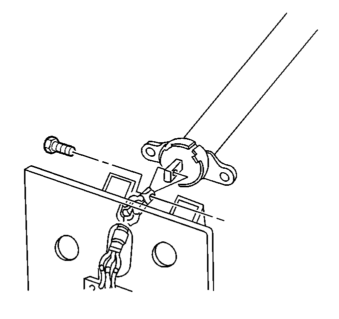
- Remove the coupler bolt
from the upper shaft assembly to the steering column shaft connection.
- Remove the steering column.
Installation Procedure

- Install the steering column
while carefully aligning into the lower steering coupler.
Notice: Use the correct fastener in the correct location. Replacement fasteners
must be the correct part number for that application. Fasteners requiring
replacement or fasteners requiring the use of thread locking compound or sealant
are identified in the service procedure. Do not use paints, lubricants, or
corrosion inhibitors on fasteners or fastener joint surfaces unless specified.
These coatings affect fastener torque and joint clamping force and may damage
the fastener. Use the correct tightening sequence and specifications when
installing fasteners in order to avoid damage to parts and systems.
Tighten
Tighten the coupler bolt of the upper shaft assembly to the steering
column shaft connection to 61 N·m (45 lb ft).

- Handstart the following
components:
| • | The upper support bracket side bolts. |
| • | The upper support bracket rear bolts. |

- Handstart the following
components:
| • | The steering column mounting nuts to the upper steering column
support studs. |
| • | The steering column mounting bracket nuts to the floor and dash
panel assembly studs. |

- Tighten the rear and side
steering column upper support bracket bolts.
Tighten
Tighten the bolts to 50 N·m (37 lb ft).
- Tighten the steering column mounting bracket nuts to the upper
support studs and the floor and dash panel assembly studs.
Tighten
Tighten the steering column mounting bracket nuts to 30 N·m
(22 lb ft).

- Install the electrical
connectors and the ground wire as follows:
| • | the strap (3) and the tape (2) to secure the fuse block |
| • | the instrument panel wiring harness extension connector (4) |
| • | the steering column harness connector (5) |
| • | the calibrator connector (7) |
| • | the DRL module connector (8) with bag (9) and secure with tape |
| • | the extension wiring harness connector (10) |
| • | the ground harness terminal (11) |
- Loosely attach the ground wire terminal bolt and washer.
Tighten
Tighten the ground wire terminal bolt and washer to 5 N·m
(44 lb in).
- Install the pull button switch connector. Refer to
Park Brake Pull Switch Replacement
in Park Brake.

- Install the park brake
auto apply switch, if damaged or malfunctioning. Refer to
Park Brake Pull Switch Replacement
in Park Brake.
- Install the transmission control/range selector assembly.
Tighten
Tighten the transmission control assembly bracket bolts to 5 N·m
(44 lb in).
- Install the ignition lock cylinder. Refer to Ignition and Key Alarm Switch Assembly - Assemble - Off Vehicle
.
- Install the parking brake pull button switch. Refer to
Park Brake Pull Switch Replacement
.
- Install the steering wheel. Refer to
Steering Wheel Replacement
.
Steering Column Replacement Column Coupling Replacement
Removal Procedure
Important: The following procedure should be not only be used when replacing worn
or damaged upper and lower steering gear shaft components, but should also
be used as a steering wheel alignment procedure.
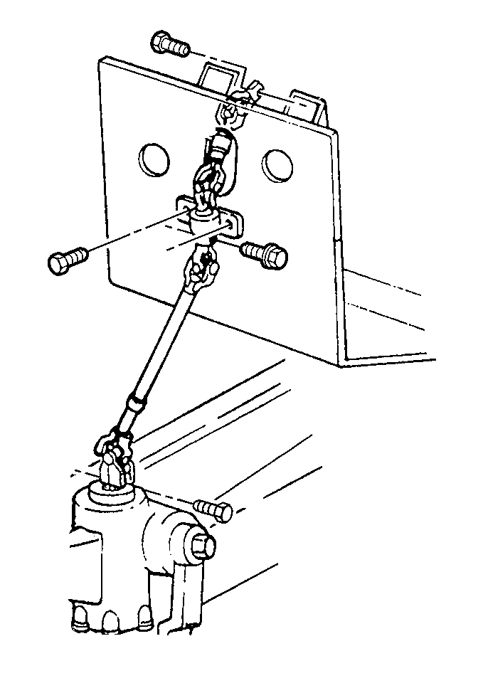
- Set the front wheels in
the straight-ahead position and the steering wheel in the LOCKED position.
- Mark the relationship of the upper steering gear coupling shaft
to the steering shaft, the lower steering gear coupling shaft to the upper
steering gear coupling shaft , and the cardan joint yoke to the steering
gear input shaft to be sure of proper installation.
- Remove the coupler bolt from the upper steering gear shaft assembly
to the steering column shaft connection.
- Remove the upper steering gear shaft boot.
- Remove the upper steering gear shaft bracket.
- Remove the upper-to-lower steering gear shaft coupler bolt.
- Remove the upper steering gear shaft assembly.
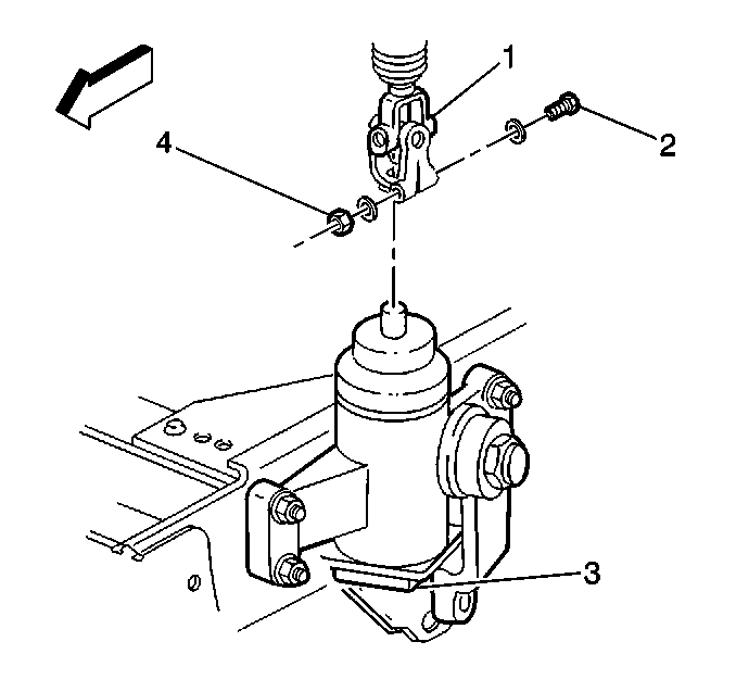
- Remove the cardan joint
nut (1) and the washer.
- Remove the cardan joint bolt (2) and the washer.
- Gently pry the cardan joint from the steering gear (3) input shaft.
A slight tapping of the yoke may be required.
Installation Procedure

Notice: Use the correct fastener in the correct location. Replacement fasteners
must be the correct part number for that application. Fasteners requiring
replacement or fasteners requiring the use of thread locking compound or sealant
are identified in the service procedure. Do not use paints, lubricants, or
corrosion inhibitors on fasteners or fastener joint surfaces unless specified.
These coatings affect fastener torque and joint clamping force and may damage
the fastener. Use the correct tightening sequence and specifications when
installing fasteners in order to avoid damage to parts and systems.
- Make a cardan joint
notch correction(s) at this time if the steering column was determined to
be misaligned (more than 5 degrees) from the steering wheel centerline.
- Otherwise follow the alignment marks on the cardan joint (1) and
the steering gear input shaft.
- Position the cardan joint on to the steering gear.
- Install the cardan joint washer and the bolt (2).
Tighten
Tighten the cardan nut to 61N·m (45 lb ft).

- Install the coupler bolt
connecting the lower steering gear shaft assembly with the upper steering
gear shaft assembly following the alignment marks.
Tighten
Tighten the bolt to 61 N·m (45 lb ft).
- Secure the upper shaft assembly to steering support.
Tighten
Tighten the bolts to 50 N·m (37 lb ft).
- Install the boot.
Tighten
Tighten the bolts to 9 N·m (80 lb in).
- Attach the upper steering shaft assembly bolt to the steering
column shaft connection following alignment marks.
Tighten
Tighten the bolt to 61 N·m (45 lb ft).


