GM Service Manual Online
For 1990-2009 cars only

Removal Procedure


    Object Number: 247483  Size: SH
  1. Set the parking brake.
  2. Block the front wheels.
  3. Raise and support the vehicle using a suitable lifting device in order to remove the weight from the spring assembly. Refer to Lifting and Jacking the Vehicle in General Information.
  4. Place the jack stands under the rear axle in order to support the axle weight.
  5. Remove the rear wheel assembly, if necessary. Refer to Wheel Removal in Tires and Wheels.
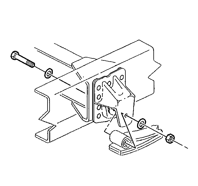
  6. Remove the following rear spring hanger components:
  7. • The eyebolt nut
    • The washers
    • The bolt

    Object Number: 247482  Size: SH
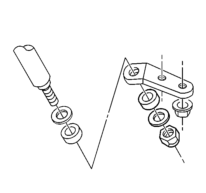
  8. Remove the following components:
  9. • The shock absorber nut
    • The washer
    • The insulator
    • The shock

    Object Number: 247484  Size: SH
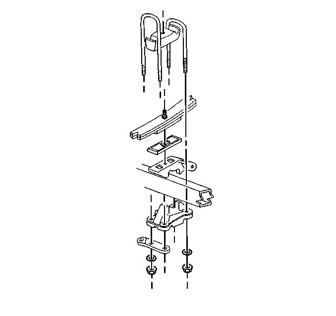
  10. Remove the U-bolt nuts and the washers.
  11. Remove the following components:
  12. • The U-bolt anchor plate
    • The seat
    • The shock absorber bracket
  13. Remove the U-bolts.
  14. Lower the axle slightly.

  15. Object Number: 247485  Size: SH
  16. Remove the following components:
  17. • The front eye bolt nut
    • The washers
    • The front eye bolt
  18. Raise and support the frame using a suitable lifting device in order to provide clearance between the spring assembly and the hanger bracket.
  19. Remove the spring assembly using a suitable hoist.
  20. Remove the following components:
  21. • The auxiliary spring
    • The bolt
    • The spacers

Installation Procedure


    Object Number: 247484  Size: SH
  1. Install the following components:
  2. • The auxiliary spring
    • The spacers
    • The bolt
  3. Install the spring assembly onto the axle pad.
  4. Install the U-bolt spacer over the center bolt.
  5. Install the U-bolts into the spacer grooves.
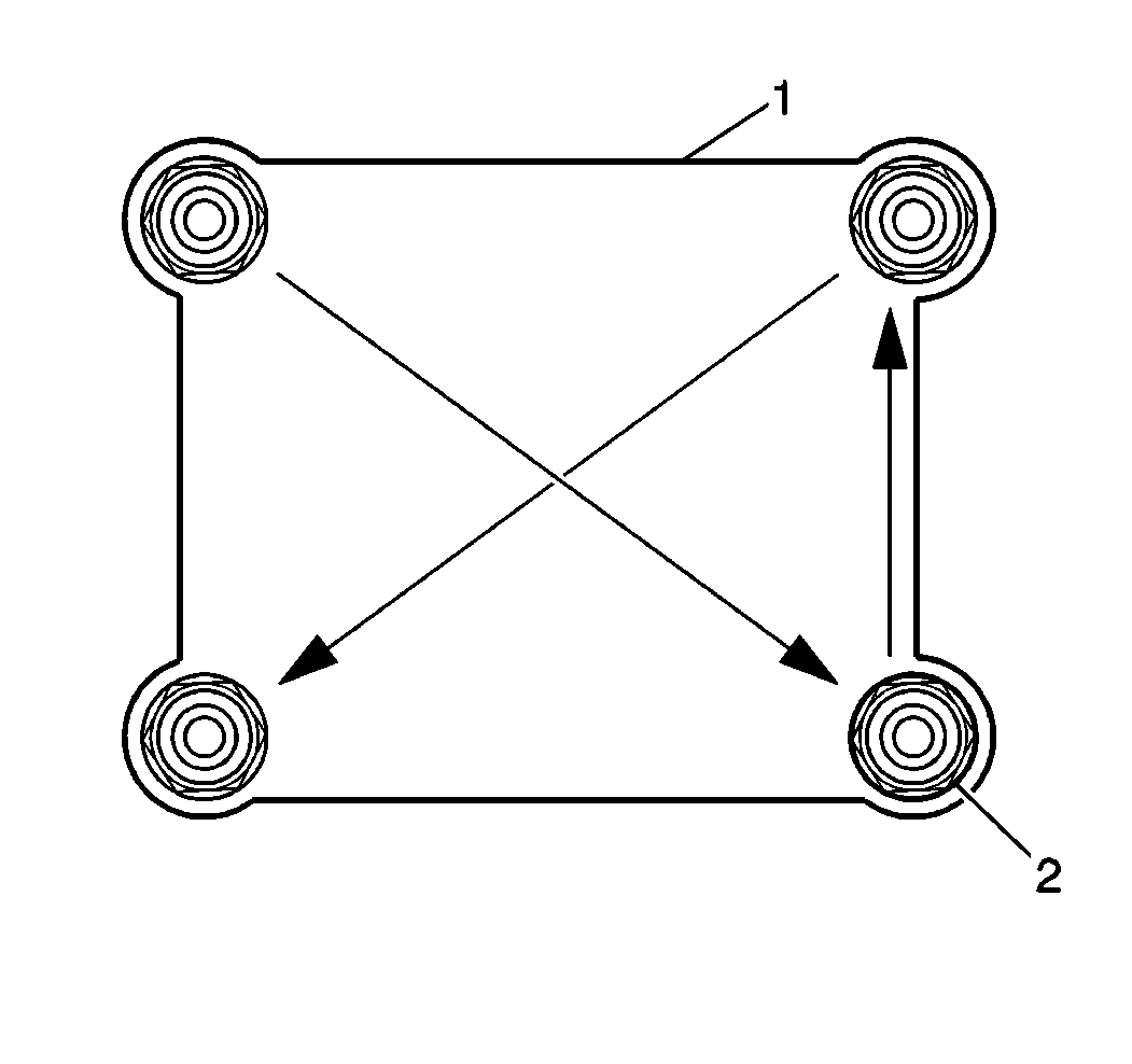
  6. Object Number: 202329  Size: SH
  7. Install the U-bolt anchor plate (1) and the seat.
  8. Install the shock absorber bracket.
  9. Notice: Use the correct fastener in the correct location. Replacement fasteners must be the correct part number for that application. Fasteners requiring replacement or fasteners requiring the use of thread locking compound or sealant are identified in the service procedure. Do not use paints, lubricants, or corrosion inhibitors on fasteners or fastener joint surfaces unless specified. These coatings affect fastener torque and joint clamping force and may damage the fastener. Use the correct tightening sequence and specifications when installing fasteners in order to avoid damage to parts and systems.

    Important: In order to properly tighten the U-bolt nuts, torque them progressively as described in the next steps.

  10. Install the U-bolt nuts and the washers (2).
  11. Tighten

    • Tighten the U-bolt nut to 100 N·m (74 lb ft), in sequence.
    • Tighten the U-bolt nut to 250 N·m (184 lb ft) in sequence.
    • Tighten the U-bolt nut to 325-350 N·m (240-259 lb ft) in sequence.

    Object Number: 247485  Size: SH
  12. Install the following components:
  13. • The front eye bolt
    • The washers
    • The front eye bolt nut

    Tighten
    Tighten the eye bolt to 415 N·m (305 lb ft).

    Object Number: 247482  Size: SH
  14. Install the following components:
  15. • The shock
    • The insulator
    • The washer
    • The nut

    Tighten
    Tighten the lower shock absorber nut to 84 N·m (62 lb ft).
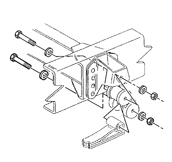

    Object Number: 247483  Size: SH
  16. Lower the frame until the hangers touch the surface of the spring eye.
  17. Install the following rear spring hanger components:
  18. • The bolt
    • The washers
    • The eye bolt nut

    Tighten
    Tighten the eye bolt to 415 N·m (305 lb ft).

  19. Install the rear wheel assembly, if necessary. Refer to Wheel Installation in Tires and Wheels.
  20. Raise the vehicle.
  21. Remove the jack stands.
  22. Lower the vehicle.
  23. Remove the blocks from the front wheels.