Removal Procedure
- Block the front wheels.
- Raise the rear axle and place the jack stands under the frame
rails. Ensure that the vehicle rear wheels are off the floor.
- Release the parking brake.
- Remove the axle shafts. Refer to
Axle Shaft Replacement
.

- Use a pry bar in order to move the tire assembly
up and down. Observe the following:
| • | If the rear wheel bearings are properly adjusted, the rear wheel
bearing end play should be 0.025-0.178 mm (0.001-0.007 in). |
| • | The movement of the rear wheel hub in relation to the backing
plate will be barely noticeable and the rear wheel will turn freely. |
| • | If the adjustment is within specification, go to steps 4 and 5
of the installation procedure. |
| • | If the movement is excessive, adjust the rear wheel bearings.
Complete all of the following steps. |
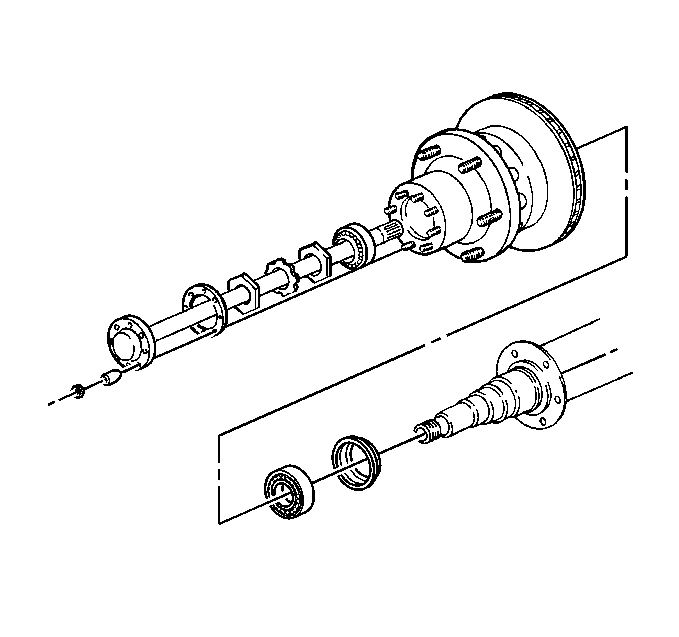
- Remove the following rear wheel bearing components:
- Loosen the inner nut.
Notice: Use the correct fastener in the correct location. Replacement fasteners
must be the correct part number for that application. Fasteners requiring
replacement or fasteners requiring the use of thread locking compound or sealant
are identified in the service procedure. Do not use paints, lubricants, or
corrosion inhibitors on fasteners or fastener joint surfaces unless specified.
These coatings affect fastener torque and joint clamping force and may damage
the fastener. Use the correct tightening sequence and specifications when
installing fasteners in order to avoid damage to parts and systems.
Important: Rotate the rear tire and wheel assembly while tightening the rear wheel
bearing inner nut in order to ensure proper seating of the rear wheel bearings.
- Rotate the rear tire and wheel assembly.
Tighten
Tighten the rear wheel bearing inner nut to 68 N·m (50 lb ft).

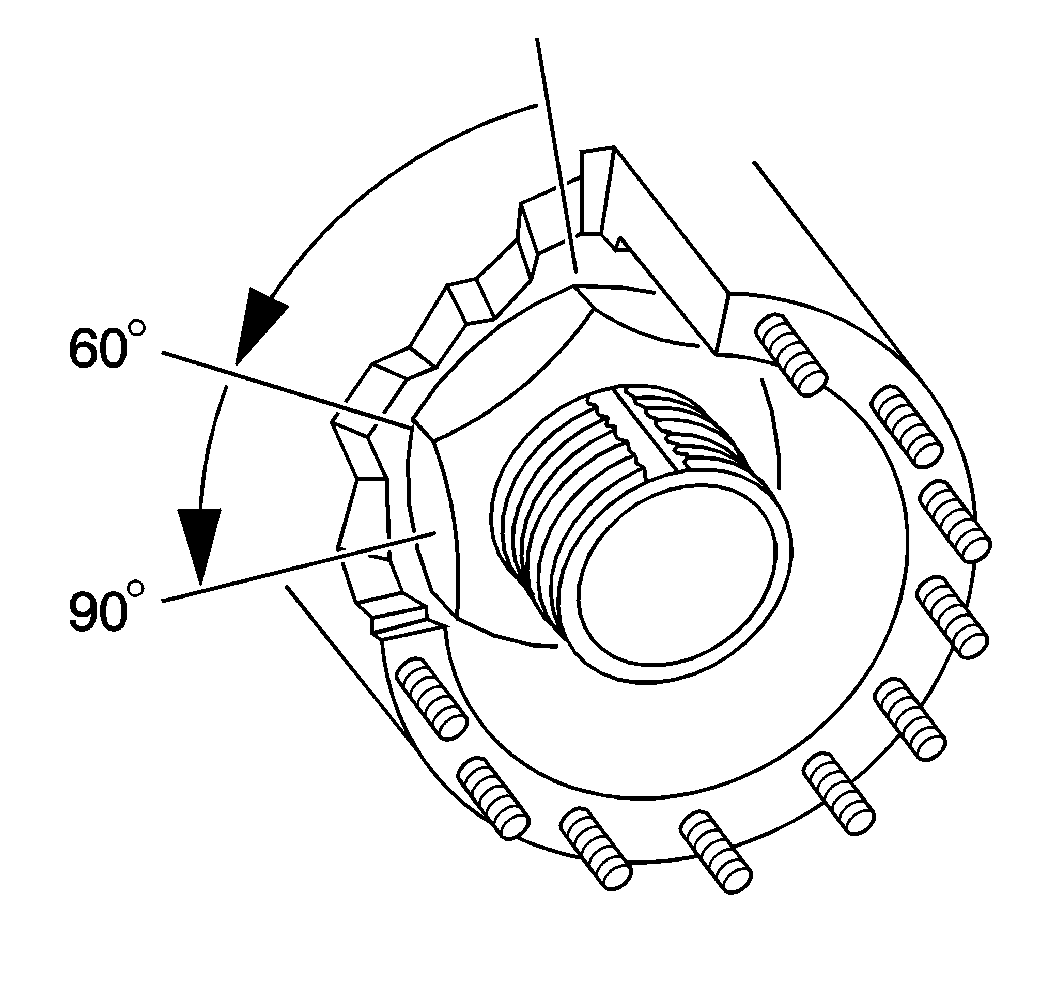
- Back off the rear wheel bearing inner nut 1/6
to 1/4 turn.
Installation Procedure
- Install the nut lock.
Notice: Use the correct fastener in the correct location. Replacement fasteners
must be the correct part number for that application. Fasteners requiring
replacement or fasteners requiring the use of thread locking compound or sealant
are identified in the service procedure. Do not use paints, lubricants, or
corrosion inhibitors on fasteners or fastener joint surfaces unless specified.
These coatings affect fastener torque and joint clamping force and may damage
the fastener. Use the correct tightening sequence and specifications when
installing fasteners in order to avoid damage to parts and systems.
- Install the outer nut.
Tighten
Tighten the outer nut to 169 N·m (125 lb ft).

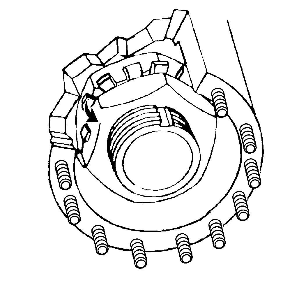
- Bend one tang of the nut lock over a flat of
the outer nut.
- Lower the rear axle housing.
- Install the rear axle shafts. Refer to
Axle Shaft Replacement
.


