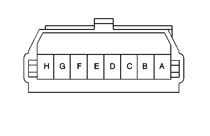
| Table 1: | Diode Network Connector |
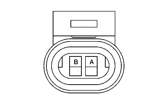
| Table 2: | Power Brake Booster Fluid Flow Switch Connector |
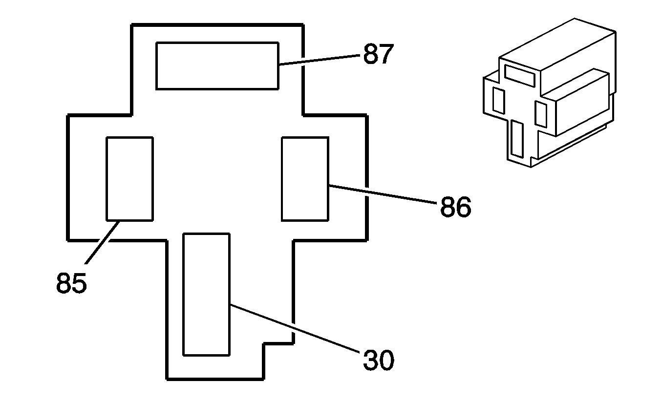
| Table 3: | Power Brake Booster Pump Relay Connector |

| |||||||
|---|---|---|---|---|---|---|---|
Connector Part Information |
| ||||||
Pin | Wire Color | Circuit No. | Function | ||||
A | ORN | 920 | Output to Park Brake Alarm | ||||
B | PPL | 680 | Output to Brake Pressure Differential Switch and EBCM | ||||
C | LT BLU | 1134 | Output to Ignition Switch and DRL Module | ||||
D | -- | -- | Not Used | ||||
E | YEL/BLK | 68 | Input from the Engine Coolant Level Switch and IP Cluster LOW COOLANT Indicator | ||||
F | WHT/BLK | 235 | Input from the IP Wiring Harness Junction Block | ||||
G | TAN/WHT | 33 | Input from the DRL Control Module | ||||
H | TAN/WHT | 33 | Input from the DRL Control Module | ||||

| |||||||
|---|---|---|---|---|---|---|---|
Connector Part Information |
| ||||||
Pin | Wire Color | Circuit No. | Function | ||||
A | LT BLU /BLK | 1928 | Input to the Power Brake Booster Fluid Flow Switch from the Power Brake Booster Pump Relay | ||||
B | BLK | 150 | Ground | ||||

| |||||||
|---|---|---|---|---|---|---|---|
Connector Part Information |
| ||||||
Pin | Wire Color | Circuit No. | Function | ||||
30 | RED | 642 | POWER BRAKE Fuse Input | ||||
85 | WHT | 17 | Stoplamps Switch Input | ||||
86 | LT BLU /BLK | 1928 | Output to Power Brake Booster Fluid Flow Switch | ||||
87 | ORN | 1470 | Output to Power Brake Booster Pump Motor | ||||
