GM Service Manual Online
For 1990-2009 cars only

Whenever moving any of the wiring, replace the wiring in the original position. Whenever moving the harnesses in order to reach a component, ensure that all the harnesses are routed correctly. Replace broken clips or retainers. Electrical problems can result from loose wiring or harnesses which shift from the original positions, or which are routed incorrectly.

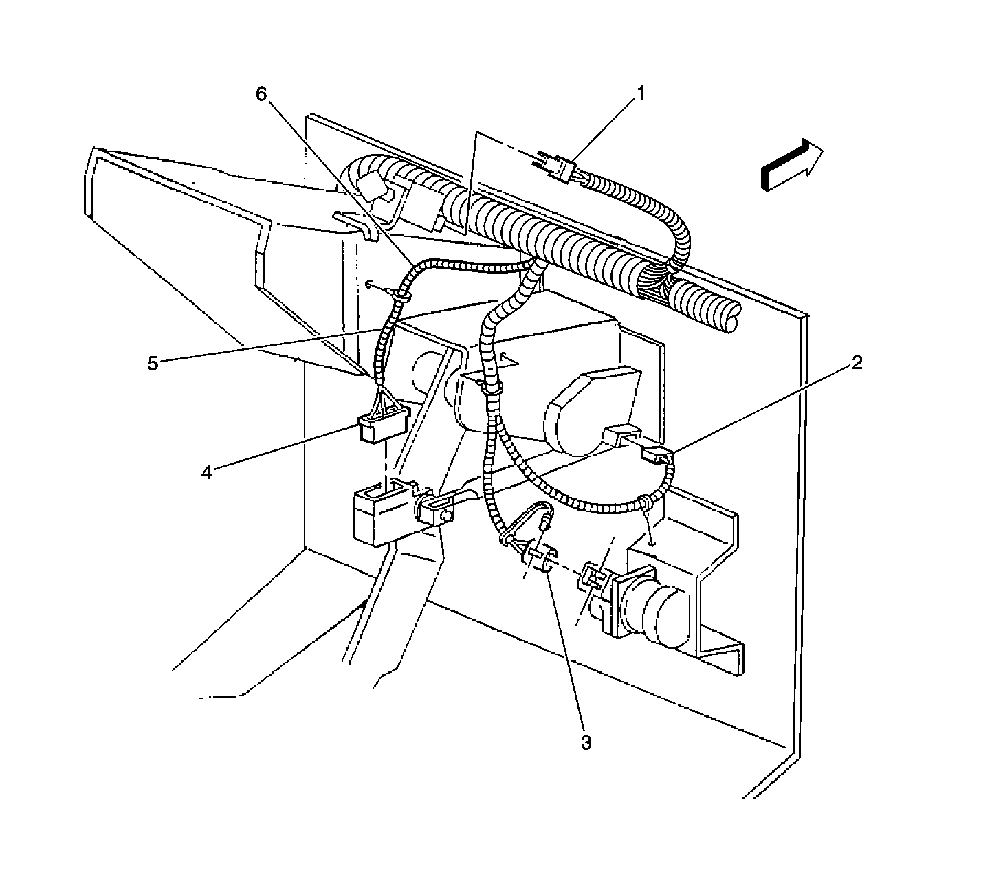
Figure 1:

Dash Wiring-Right Side


Object Number: 290833  Size: LF
(1)Park Brake Pull Button Switch Connector
(2)Windshield Wiper Pulse Control Module Connector
(3)Accelerator Pedal Position (APP) Sensor Connector
(4)Stoplamp Switch Connector
(5)S223
(6)S224
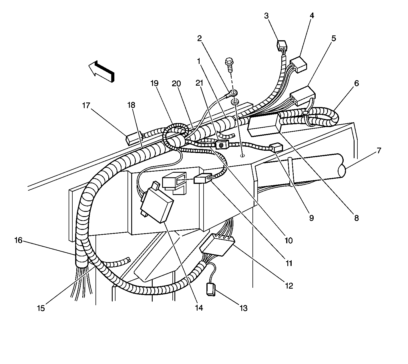
Figure 2:

Dash Wiring-Top Left


Object Number: 290830  Size: LF
(1)S222, S225, S226
(2)G200
(3)Park Brake Pull Button Switch Connector
(4)C203
(5)C202
(6)S227, S228, S229, S230, S231, S232
(7)Steering Column
(8)Fuse Block (located by body builder)
(9)Transmission Range (TR) Shift Control Connector
(10)S211, S212, S213
(11)Daytime Running Lamps (DRL) Diode Module Connector
(12)Steering Column Connector
(13)Diode Network
(14)Speedometer Adapter Module Connector
(15)S215, S216, S217, S219, S220, S236
(16)S200
(17)DRL Control Module
(18)S201, S202, S203, S204, S205, S206
(19)S221
(20)S207, S208, S209, S210
(21)Park Brake Alarm (located by body builder)
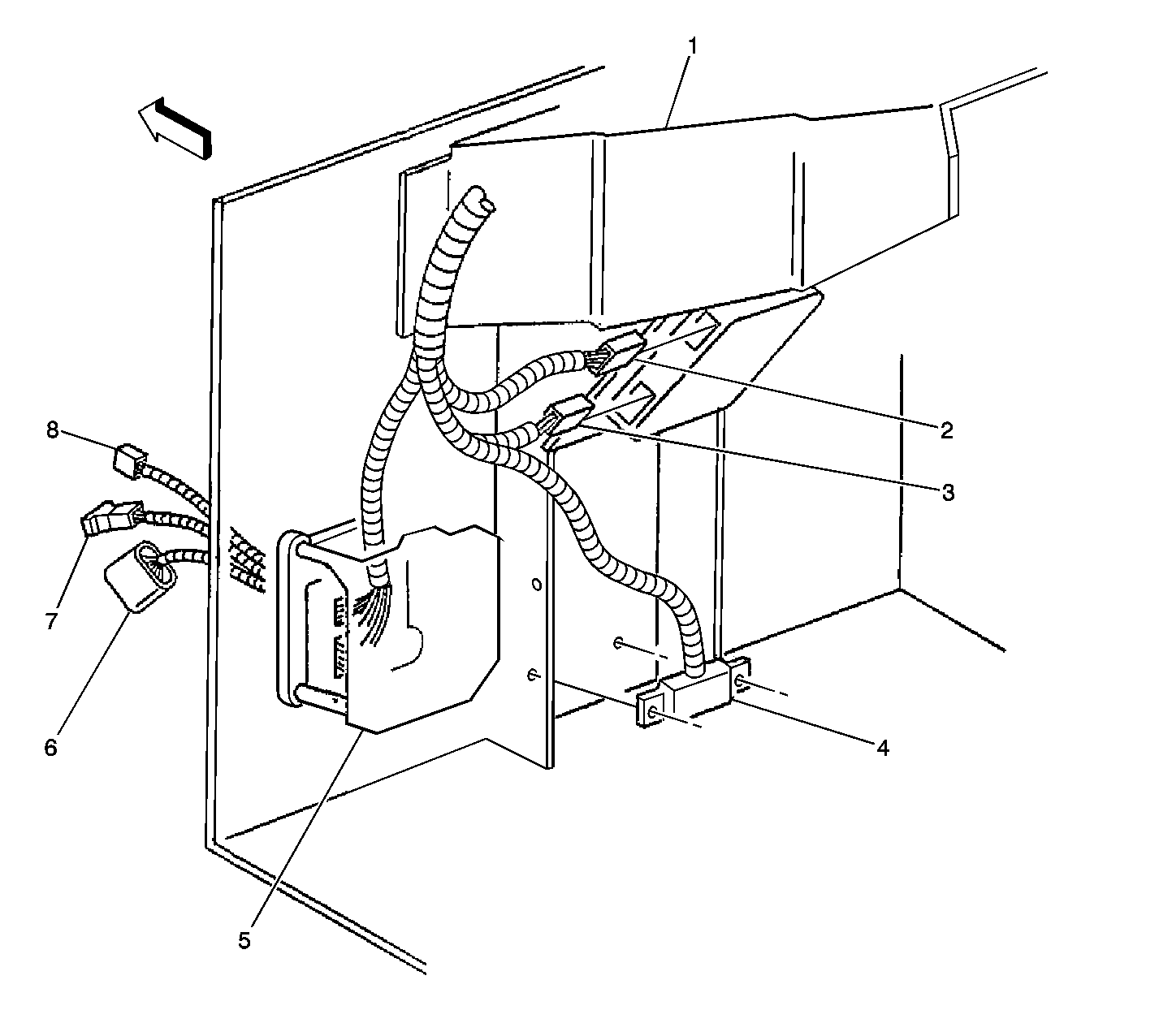
Figure 3:

Dash Wiring-Lower Left


Object Number: 290827  Size: LF
(1)Steering Column Support
(2)Throttle Actuator Control (TAC) Module Connector C2
(3)Throttle Actuator Control (TAC) Module Connector C1
(4)Data Link Connector (DLC)
(5)IP Wiring Harness Junction Block
(6)C101
(7)C113
(8)C104
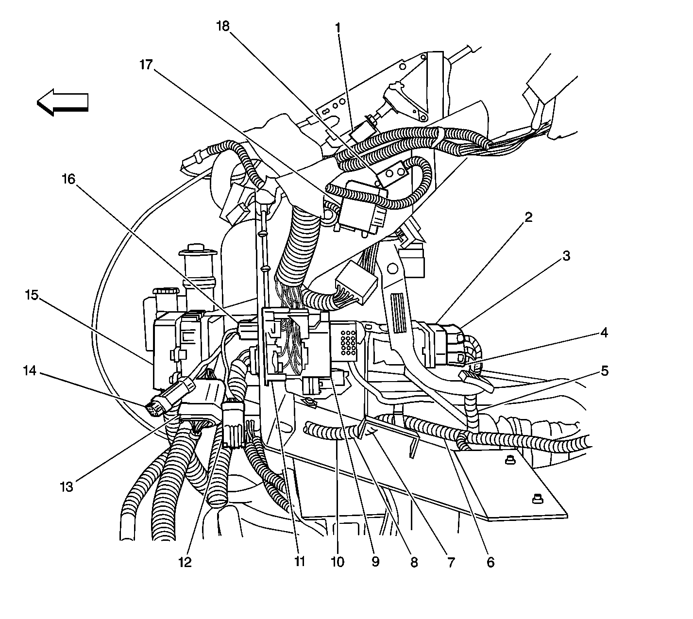
Figure 4:

Engine Harness to IP Harness


Object Number: 240960  Size: LF
(1)Park Brake Pull Button Switch
(2)Powertrain Control Module (PCM)
(3)PCM Connector C1
(4)PCM Connector C2
(5)S110
(6)S113
(7)S114
(8)S115
(9)IP Wiring Harness Junction Block
(10)S116
(11)C100
(12)C104
(13)C101
(14)C113
(15)Engine Wiring Harness Junction Block (Underhood Fuse Relay Center)
(16)P100
(17)Speedometer Adapter Module
(18)Daytime Running Lamps (DRL) Diode Module
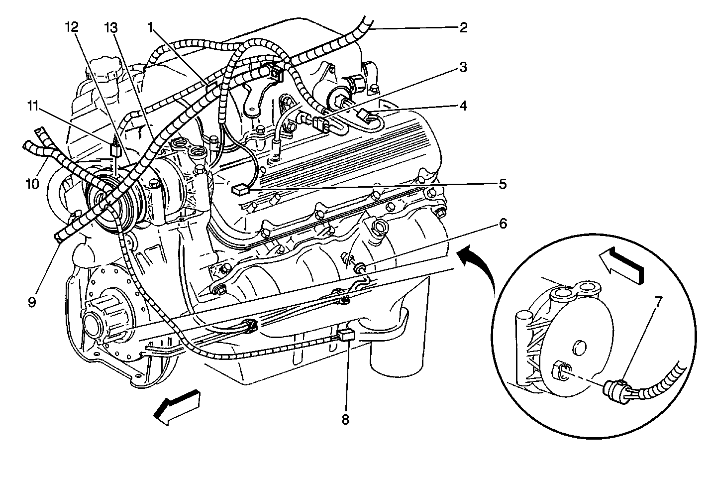
Figure 5:

Engine Harness-Left Side


Object Number: 293314  Size: MF
(1)S108, S109
(2)Engine Harness
(3)EVAP Connector
(4)EGR Connector
(5)C102
(6)Knock Sensor Connector
(7)A/C Compressor Cutoff Switch Connector
(8)Wheel Speed Sensor Connector
(9)S113
(10)S110
(11)A/C Compressor Clutch Connector
(12)A/C Compressor
(13)S106, S107, S111, S112
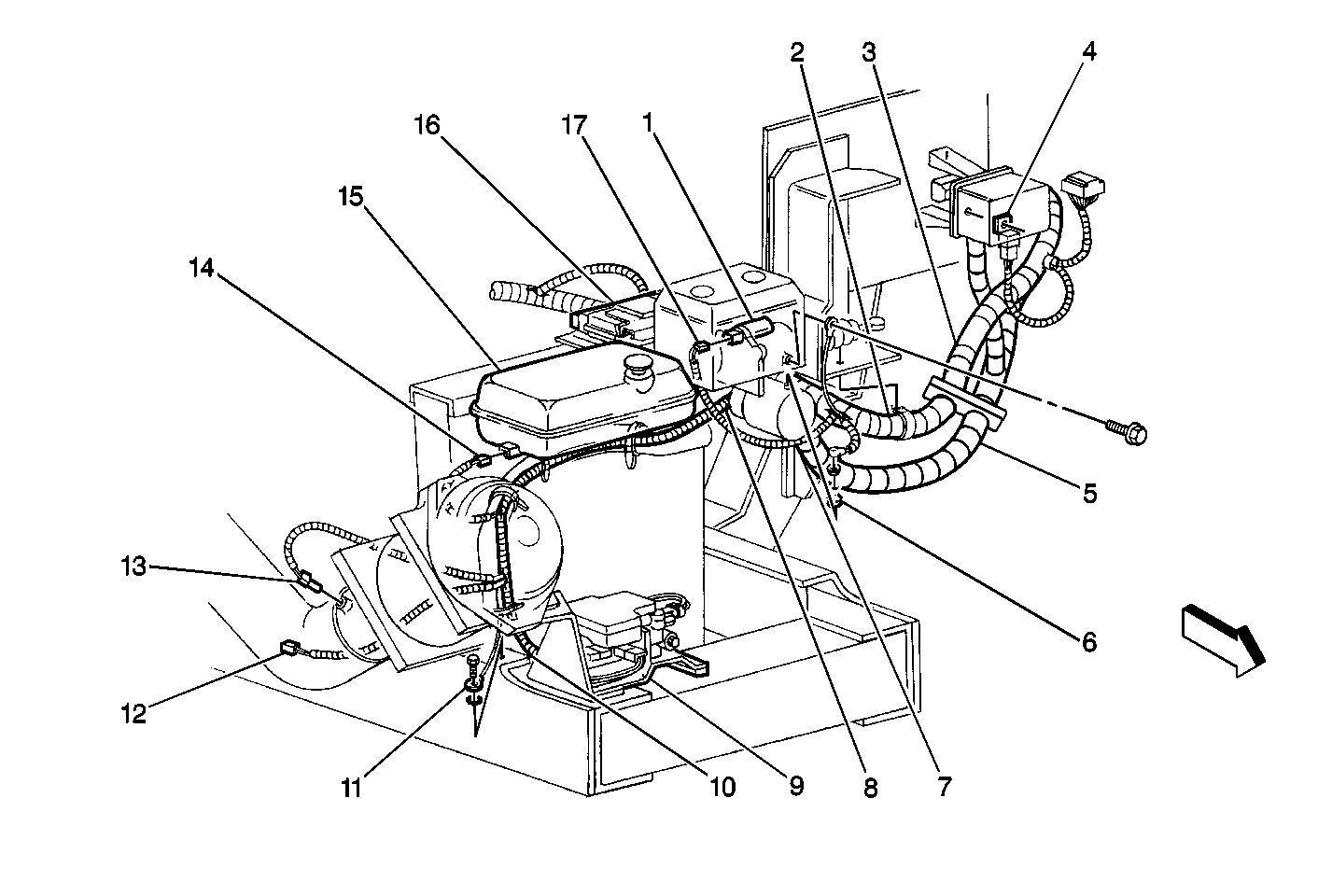
Figure 6:

Radiator Support Wiring


Object Number: 240952  Size: MF
(1)Power Brake Booster Pump
(2)S122
(3)S123
(4)Power Brake Booster Pump Relay
(5)S120
(6)Power Brake Booster Pump Motor
(7)S121
(8)S117, S118
(9)ABS Module
(10)S119
(11)G101
(12)RH Wheel Speed Sensor
(13)Intake Air Temperature (IAT) Sensor
(14)Engine Coolant Level Switch
(15)Engine Coolant Surge Tank
(16)Powertrain Control Module (PCM)
(17)Power Brake Booster Fluid Flow Indicator Switch
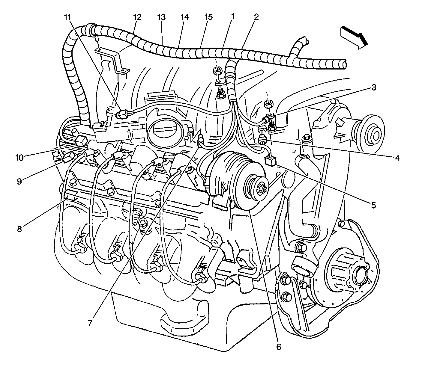
Figure 7:

Engine Harness Right Front


Object Number: 240962  Size: LF
(1)S101
(2)S105
(3)G102
(4)Manifold Absolute Pressure (MAP) Sensor
(5)Crankshaft Position (CKP) Sensor
(6)Generator
(7)Throttle Position (TP) Sensor
(8)G103, G104, G109
(9)Engine Coolant Temperature (ECT) Sensor
(10)C103
(11)Throttle Actuator Motor
(12)S100
(13)S103
(14)S102
(15)Engine Harness
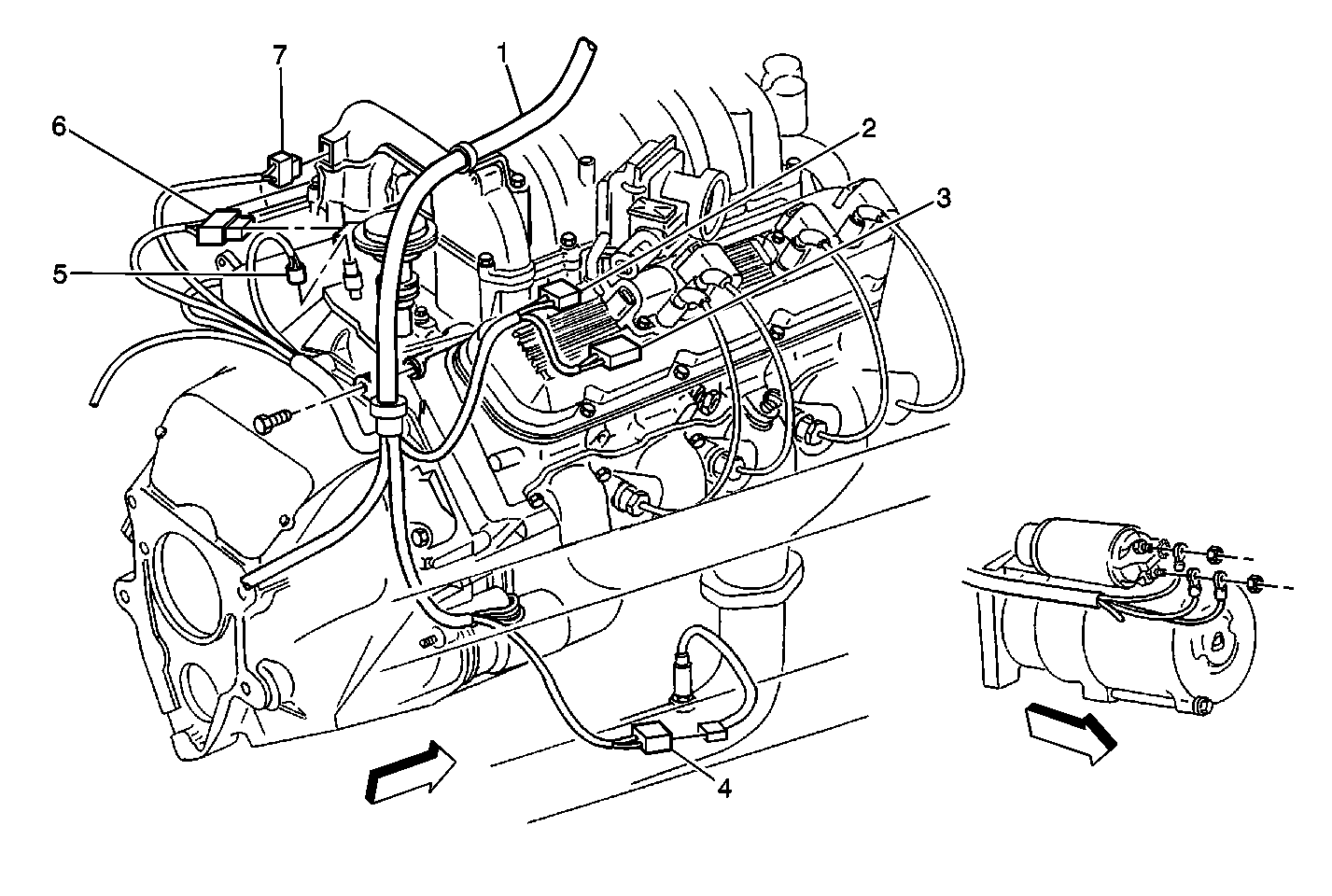
Figure 8:

Engine Harness-Right Rear


Object Number: 293315  Size: MF
(1)Engine Harness
(2)C103
(3)Engine Coolant Temperature (ECT) Sensor Connector
(4)HO2S Bank 2 Sensor 1 Connector
(5)Engine Oil Pressure Sensor Connector
(6)Camshaft Position (CMP) Sensor Connector
(7)C105
Figure 9:

Inline Connectors on Top of the Transmission
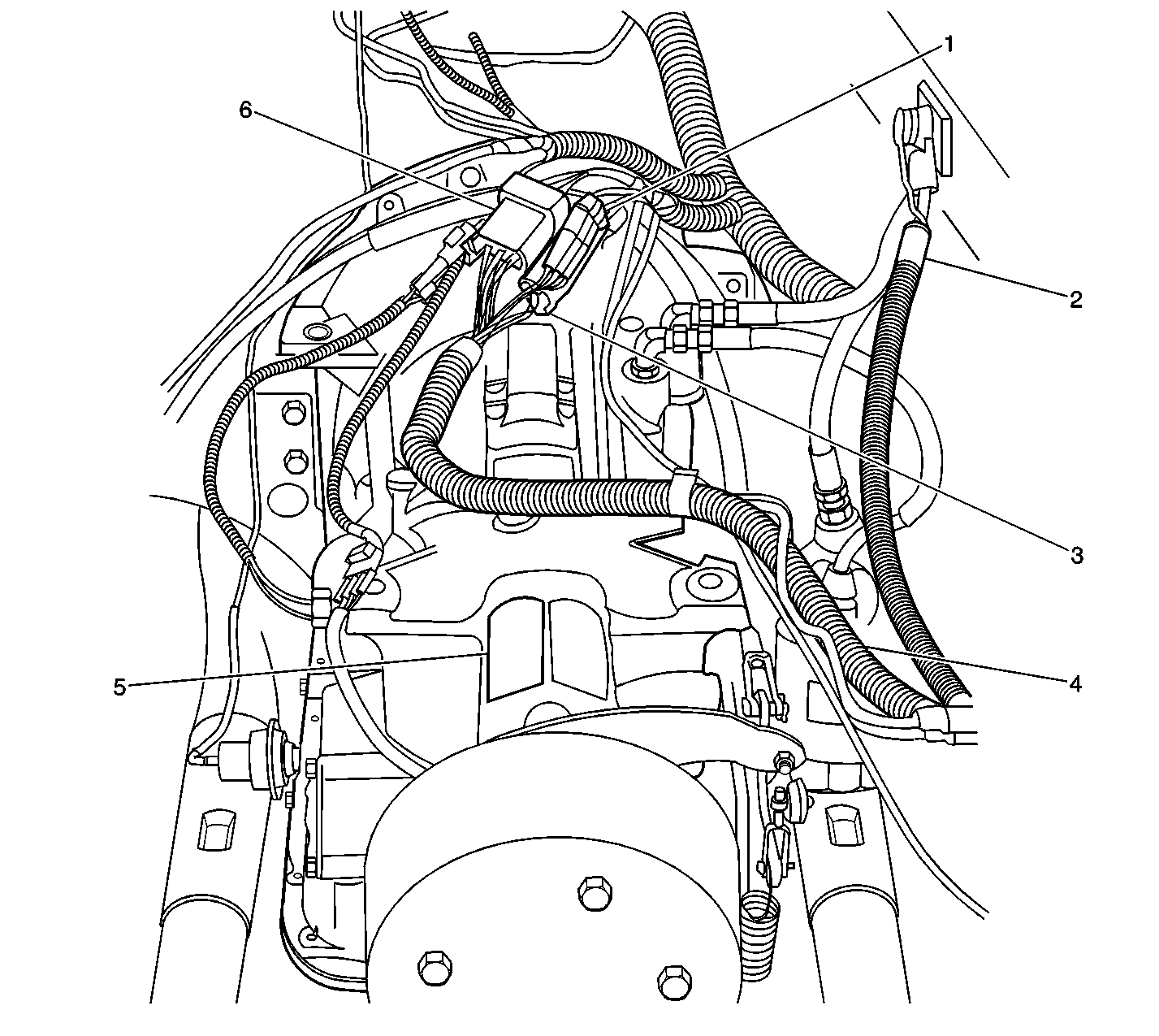

Object Number: 261911  Size: LF
(1)C112
(2)Battery Cable
(3)C111
(4)S300
(5)Transmission
(6)C110
Figure 10:

Park Brake Harness Connections and Grounds
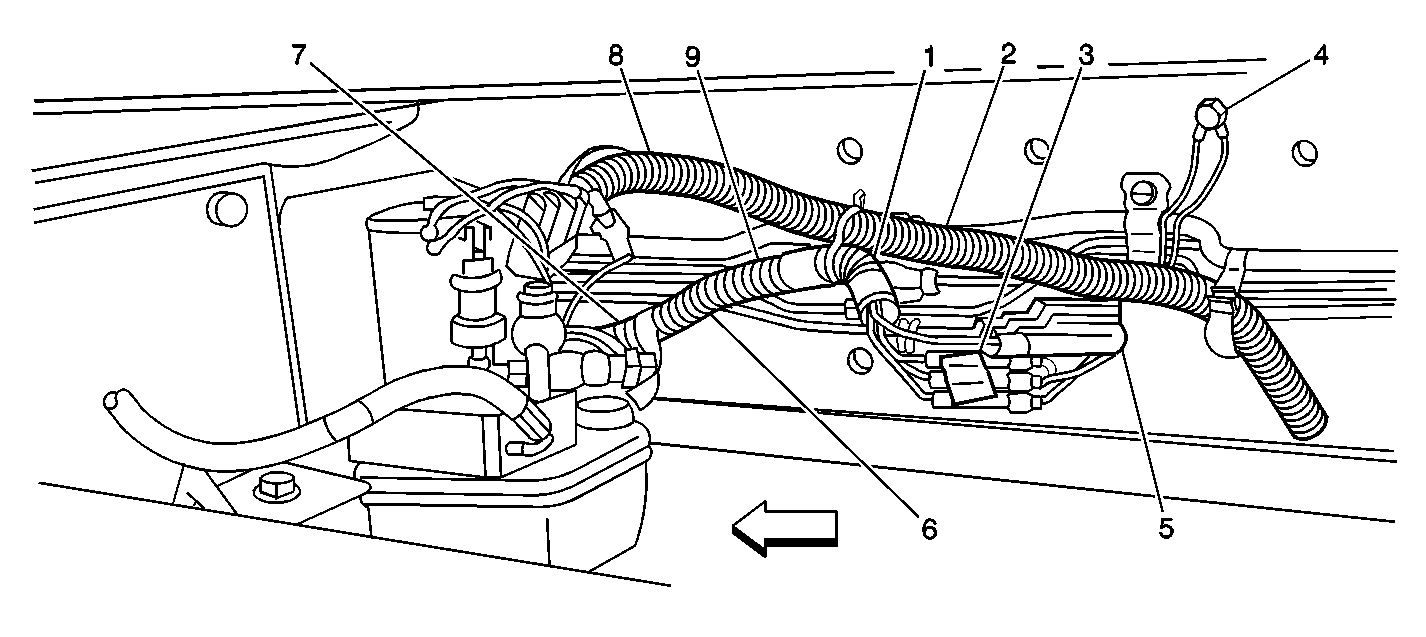

Object Number: 317451  Size: SF
(1)S302
(2)Rear Chassis Harness
(3)C300
(4)G300, G400
(5)C301
(6)S306, S307, S308, S309
(7)S303, S304, S305
(8)S407
(9)Auto Apply Park Brake Harness