| Table 1: | Brake Pressure Differential Switch Connector |
| Table 2: | EBCM Connector C1 |
| Table 3: | EBCM Connector C2 |
| Table 4: | EBCM Connector C3 |
| Table 5: | Wheel Speed Sensor |
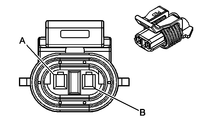
| |||||||
|---|---|---|---|---|---|---|---|
Connector Part Information |
| ||||||
Pin | Wire Color | Circuit No. | Function | ||||
A | PPL | 680 | ABS Pressure Differential Switch Signal | ||||
B | BLK | 150 | Ground G104 | ||||
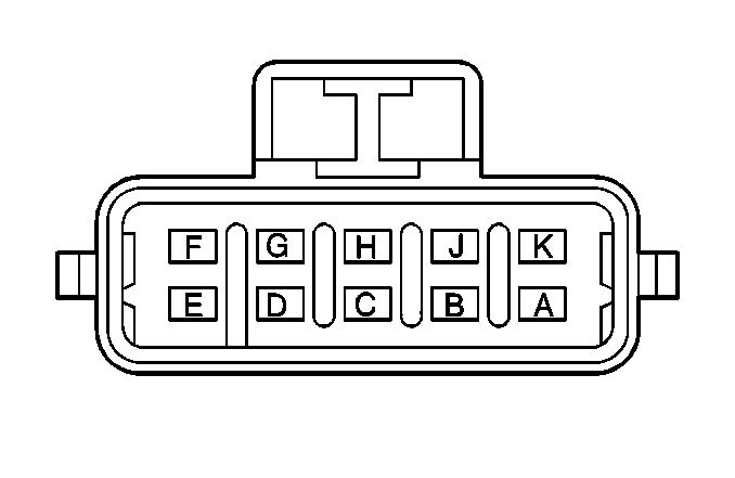
| |||||||
|---|---|---|---|---|---|---|---|
Connector Part Information |
| ||||||
Pin | Wire Color | Circuit No. | Function | ||||
A | BRN | 241 | BRAKE Fuse 18 Output | ||||
B | LT GRN | 867 | ABS Failure Indicator Lamp Control | ||||
C | PPL | 420 | Stoplamp Switch Input | ||||
D | -- | -- | Not Used | ||||
E | YEL/BLK | 1827 | Input from the Speedometer Adapter Module | ||||
F | TAN/WHT | 799 | ABS Diagnostic Link (UART) | ||||
G | PPL | 1807 | Serial Data Signal - Class 2 | ||||
H | PPL | 680 | ABS Brake Pressure Differential Switch Signal | ||||
J | BLK | 150 | Signal Ground, G104 | ||||
K | -- | -- | Not Used | ||||
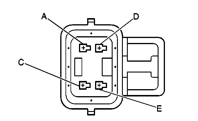
| |||||||
|---|---|---|---|---|---|---|---|
Connector Part Information |
| ||||||
Pin | Wire Color | Circuit No. | Function | ||||
A | LT BLU | 830 | Wheel Speed Sensor High, Left Front | ||||
B | -- | -- | Not Used | ||||
C | DK GRN | 872 | Wheel Speed Sensor High, Right Front | ||||
D | YEL | 873 | Wheel Speed Sensor Low, Left Front | ||||
E | TAN | 833 | Wheel Speed Sensor Low, Right Front | ||||
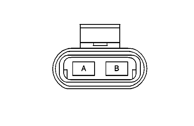
| |||||||
|---|---|---|---|---|---|---|---|
Connector Part Information |
| ||||||
Pin | Wire Color | Circuit No. | Function | ||||
A | RED | 442 | ABS Maxi-Fuse 51 Output - Pump Motor feed | ||||
B | BLK | 150 | Ground G101 | ||||
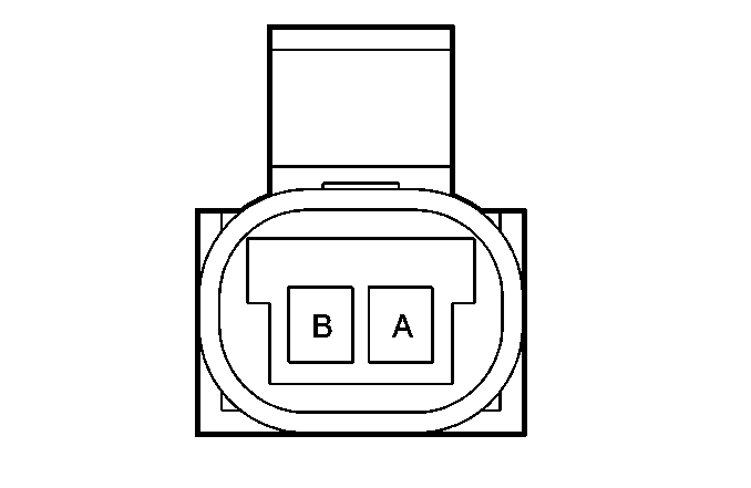
| |||||||
|---|---|---|---|---|---|---|---|
Connector Part Information |
| ||||||
Pin | Wire Color | Circuit No. | Function | ||||
A | LT BLU | 830 | WSS Signal High (LF) | ||||
A | DK GRN | 872 | WSS Signal High (RF) | ||||
B | YEL | 873 | WSS Signal Low (LF) | ||||
B | TAN | 833 | WSS Signal Low (RF) | ||||
