GM Service Manual Online
For 1990-2009 cars only
Makes
🢒
Chevrolet
🢒
1998
🢒
Chevy P42 Commercial Chassis
🢒
Engine
🢒
Engine Controls - 6.5L (L65)
🢒 Engine Controls Schematics
Figure
1:
Cell 22: PCM Power and Grounding, MIL and Service Throttle Indicators, and DLC
Engine Controls Components
Powertrain Control Module Description
Cell 22: Glowplug Controls
OBD II Symbol Description Notice
P32 Cell 81(1)
Cell 11: GAUGES and TRANS fuses
Cell 10: Ignition Switch and Fuse Block
Cell 11: ECM-I fuse [L65]
Cell 10: Fuse Block
Cell 11: ENG-BAT and ECM-BAT fuses
Handling ESD Sensitive Parts Notice
Cell 44: Diesel, ABS Power and Grounding, DLC Output
Cell 14: G200
Cell 14: S150 and S101 [L65]
Cell 14: G108 [L65]
Figure
2:
Cell 22: Glowplug Controls
Engine Controls Components
Glow Plug System Description
Cell 22: Glowplug Controls 2 - Federal Emissions
Cell 22:A/T Controls 4 - TR, TFT, TISS, and PC Solenoid Valve
OBD II Symbol Description Notice
Cell 10: Battery, Starter and Junction Block
Cell 10: Ignition Switch and Fuse Block
Cell 11: ECM-I fuse [L65]
Cell 11: GAUGES and TRANS fuses
P32 Cell 81(1)
Handling ESD Sensitive Parts Notice
Cell 14: G104 [L65]
Cell 14: G104 [L65]
Figure
3:
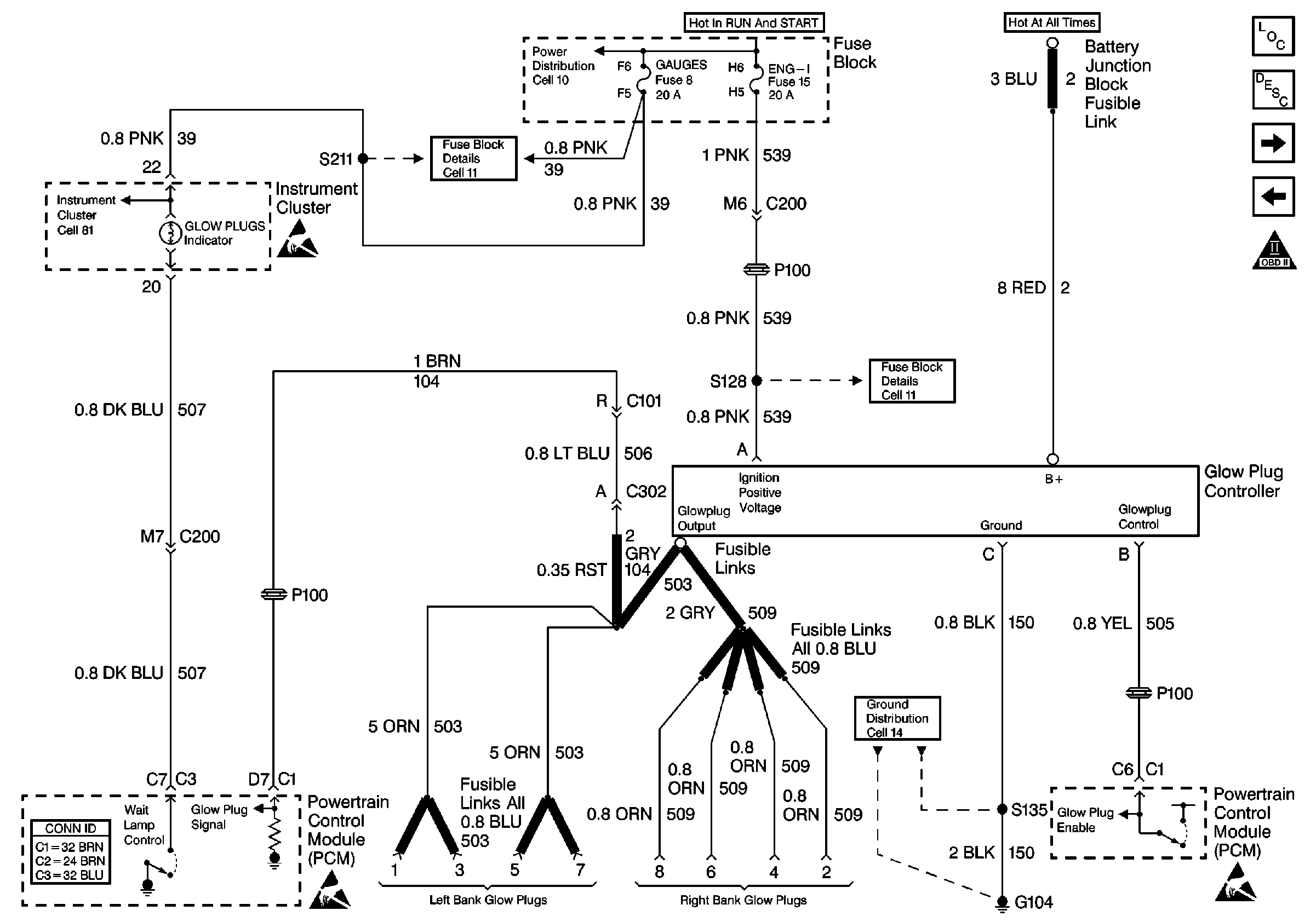
Cell 22: Glowplug Controls 2 -- Federal Emissions
Engine Controls Components
Glow Plug System Description
Cell 22: Glowplug Controls 3 - Export
Cell 22: Glowplug Controls
OBD II Symbol Description Notice
P32 Cell 81(1)
Handling ESD Sensitive Parts Notice
Cell 11: GAUGES and TRANS fuses
Cell 11: ECM-I fuse [L65]
Cell 10: Battery, Starter and Junction Block
Handling ESD Sensitive Parts Notice
Cell 14: G104 [L65]
Handling ESD Sensitive Parts Notice
Figure
4:
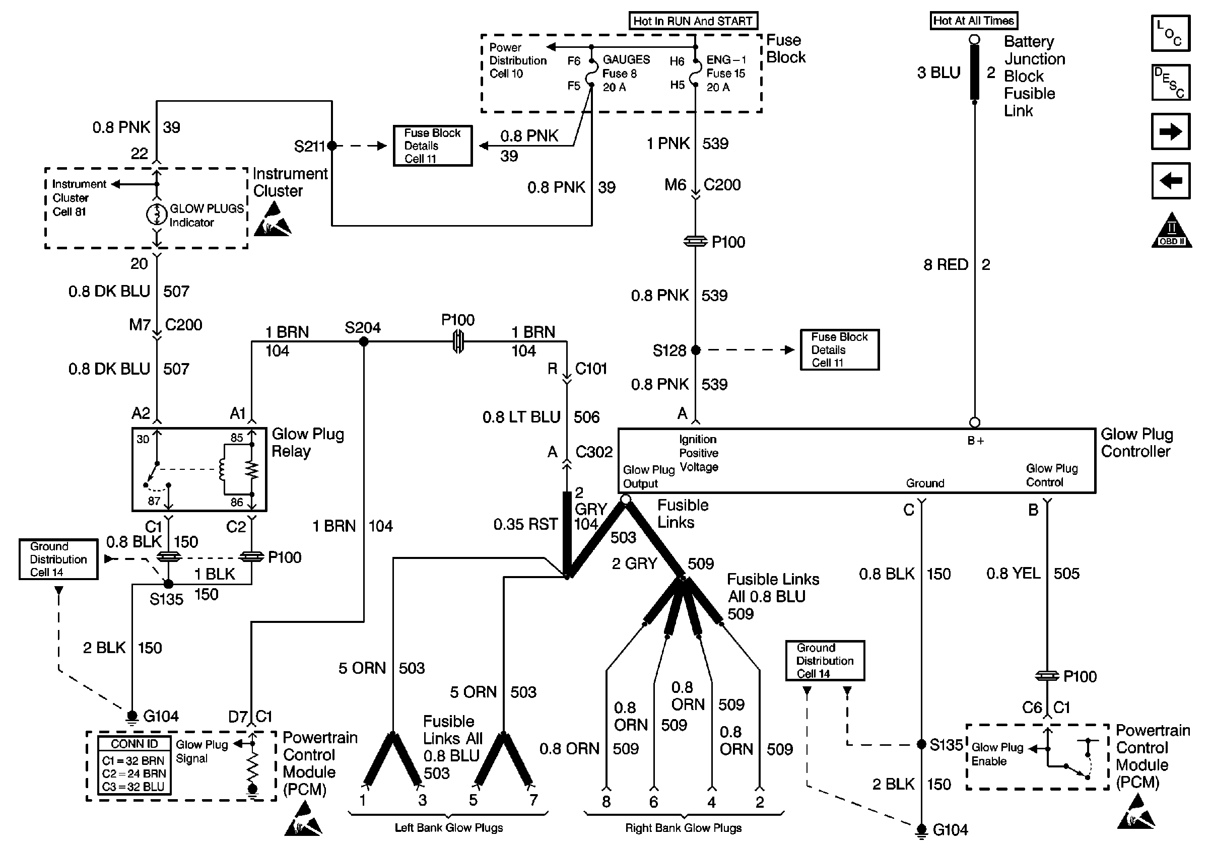
Cell 22: Glowplug Controls 3 -- Export
Engine Controls Components
Glow Plug System Description
Cell 22: CKP and Injection Timing Stepper Motor
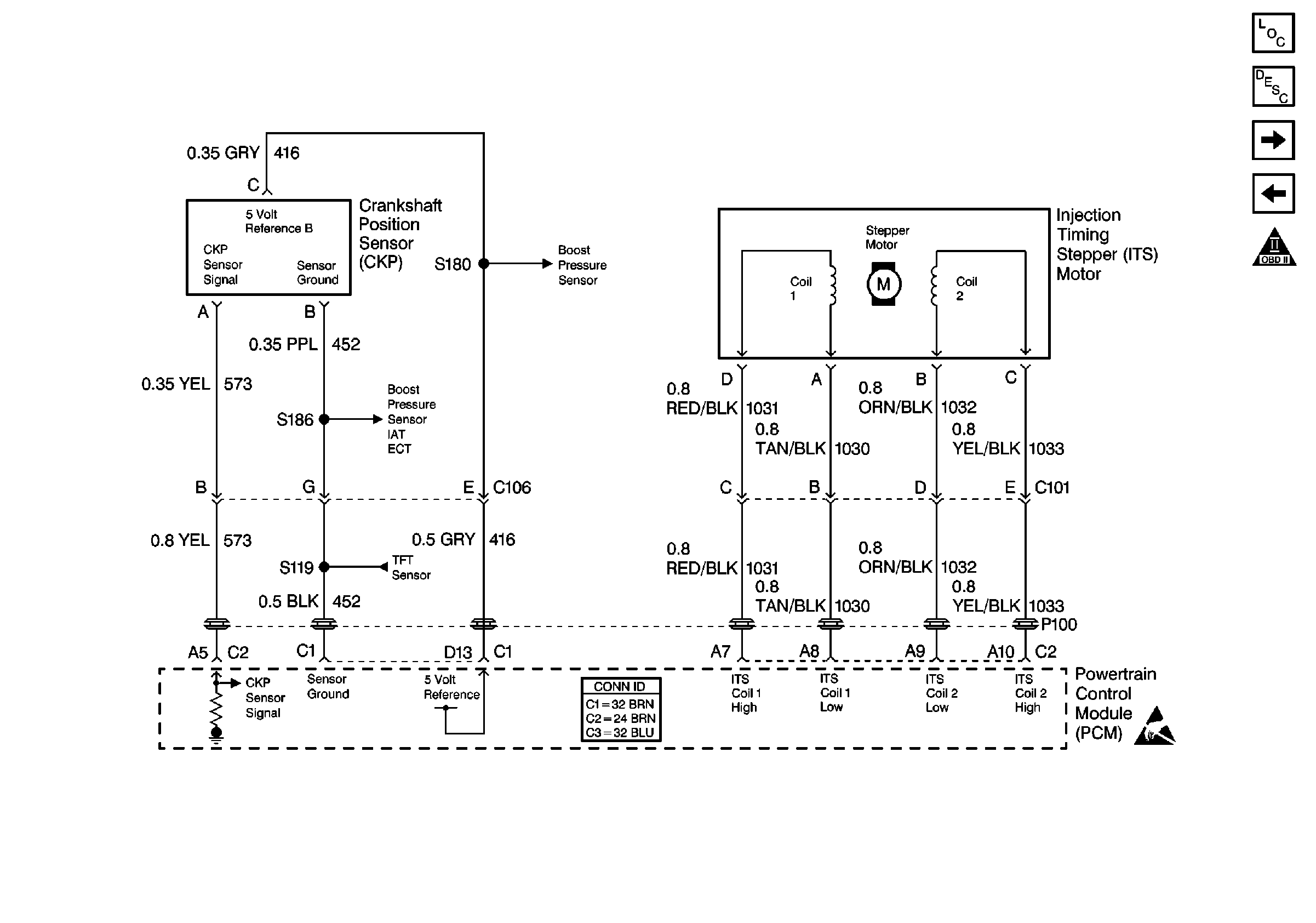
Cell 22: Glowplug Controls 2 - Federal Emissions
OBD II Symbol Description Notice
P32 Cell 81(1)
Handling ESD Sensitive Parts Notice
Cell 11: GAUGES and TRANS fuses
Cell 11: ECM-I fuse [L65]
Cell 10: Battery, Starter and Junction Block
Handling ESD Sensitive Parts Notice
Cell 14: G104 [L65]
Handling ESD Sensitive Parts Notice
Figure
5:
Cell 22: CKP and Injection Timing Stepper Motor
Engine Controls Components
Information Sensors/Switches Description
Cell 22: Fuel Pump Controls
Cell 22: Glowplug Controls 3 - Export
OBD II Symbol Description Notice
Cell 22: Engine Data Sensors and Wastegate Solenoid
Handling ESD Sensitive Parts Notice
Figure
6:
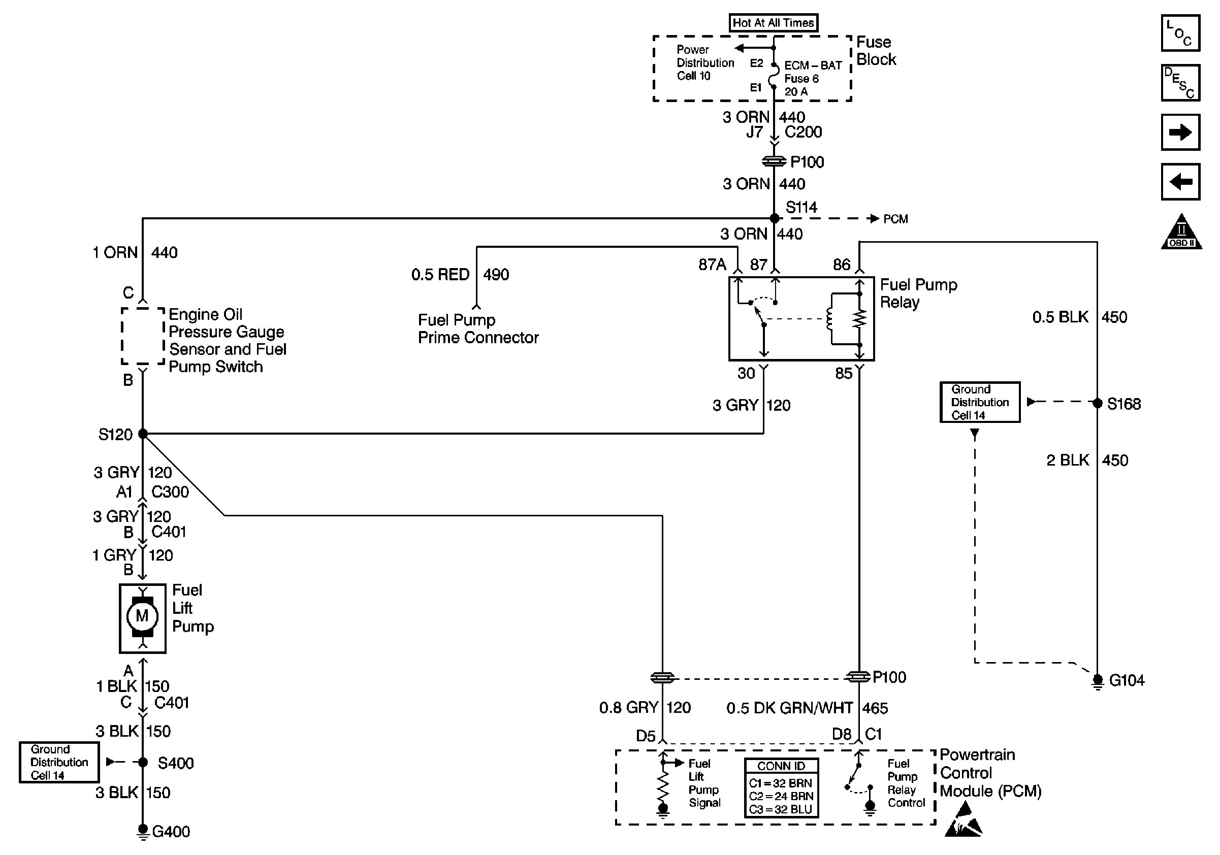
Cell 22: Fuel Pump Controls
Engine Controls Components
Fuel Supply Component Description
Cell 22: Water in Fuel Circuit, Fuel Heater and Temperature Sensor
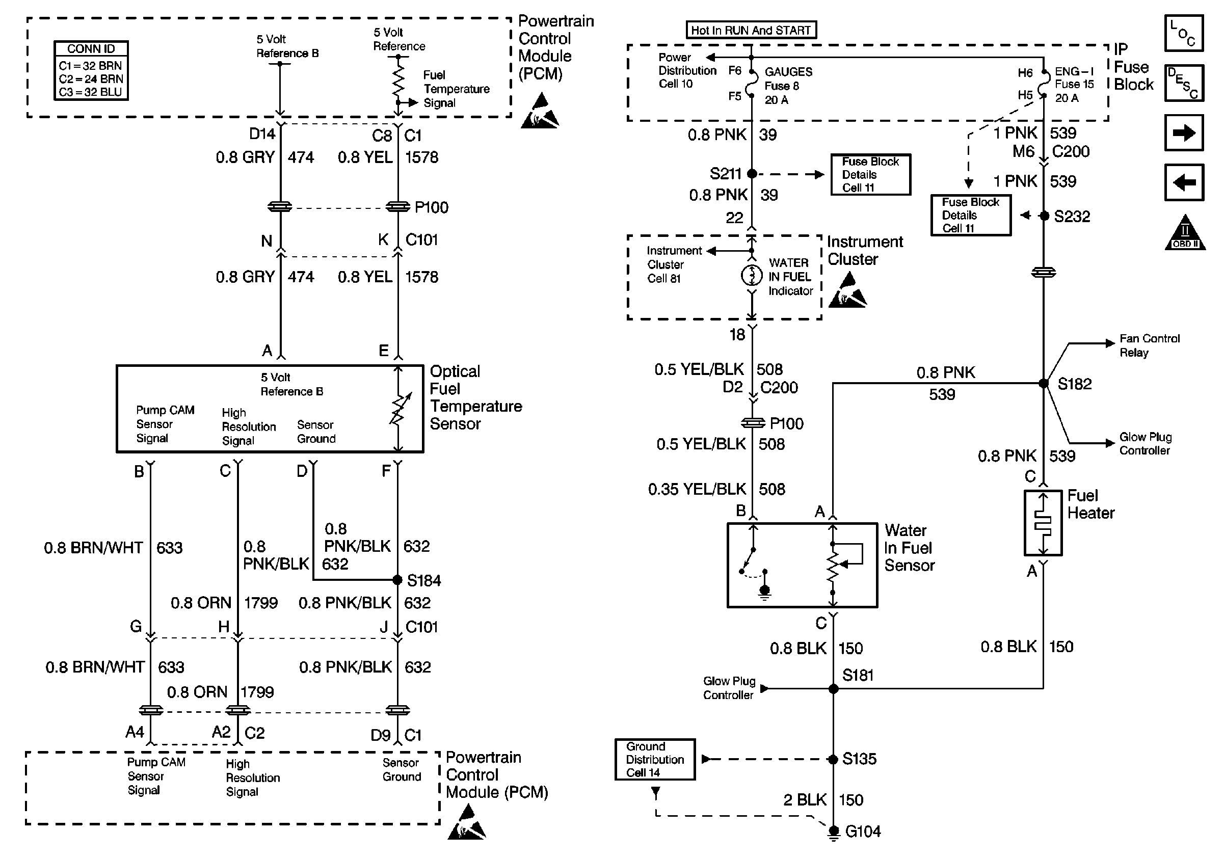
Cell 22: CKP and Injection Timing Stepper Motor
OBD II Symbol Description Notice
Cell 11: ECM-I fuse [L65]
Cell 10: Fuse Block
Cell 14: G104 [L65]
Handling ESD Sensitive Parts Notice
Cell 14: G350, G400, G401, and G402
Figure
7:
Cell 22: Water in Fuel Circuit, Fuel Heater and Temperature Sensor
Engine Controls Components
Information Sensors/Switches Description
Cell 22: Engine Shutoff Solenoid, Fuel Solenoid Driver
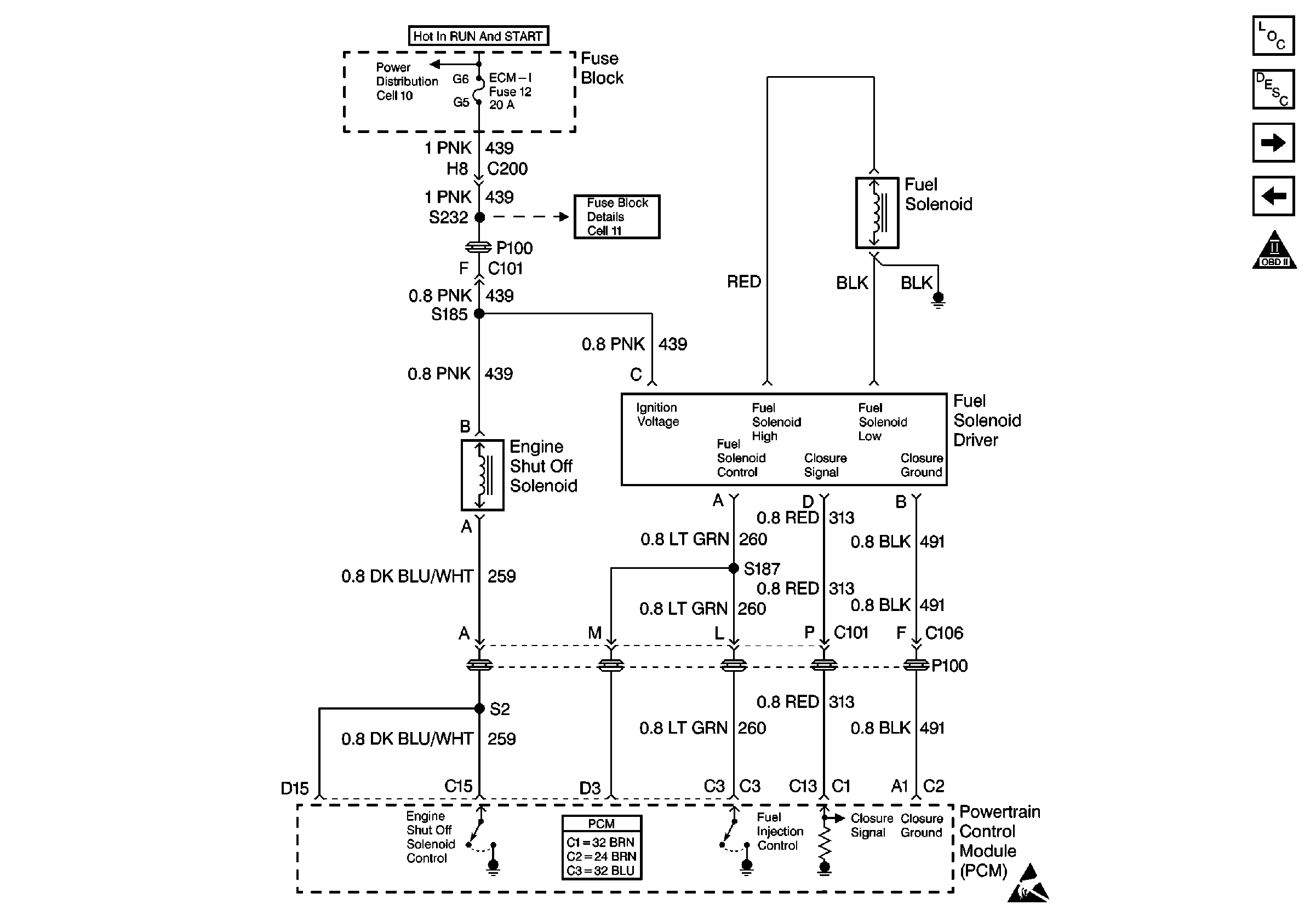
Cell 22: Fuel Pump Controls
OBD II Symbol Description Notice
P32 Cell 81(1)
Cell 10: Ignition Switch and Fuse Block
Handling ESD Sensitive Parts Notice
Cell 11: GAUGES and TRANS fuses
Cell 11: ECM-I fuse [L65]
Cell 22: Engine Data Sensors and Wastegate Solenoid
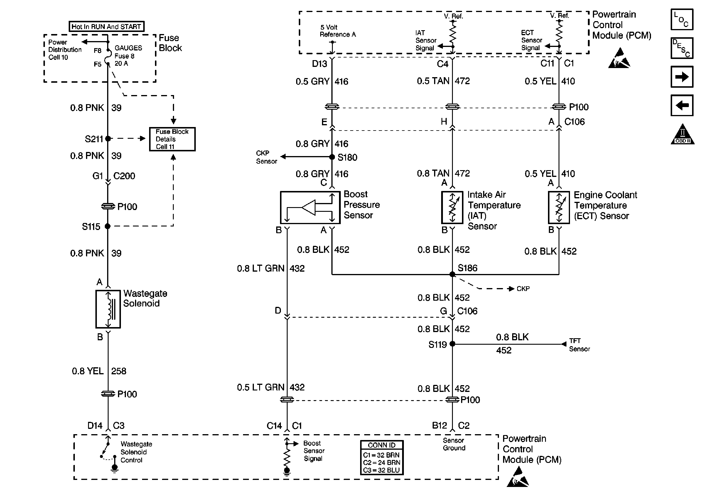
Cell 22: Glowplug Controls 2 - Federal Emissions
Cell 14: G104 [L65]
Handling ESD Sensitive Parts Notice
Figure
8:
Cell 22: Engine Shutoff Solenoid, Fuel Solenoid Driver
Engine Controls Components
Fuel System Description
Cell 22: Engine Data Sensors and Wastegate Solenoid
Cell 22: Water in Fuel Circuit, Fuel Heater and Temperature Sensor
OBD II Symbol Description Notice
Cell 10: Ignition Switch and Fuse Block
P32 Cell 11: 03
Handling ESD Sensitive Parts Notice
Figure
9:
Cell 22: Engine Data Sensors and Wastegate Solenoid
Engine Controls Components
Information Sensors/Switches Description
Cell 22: VSS Circuit
Cell 22: Engine Shutoff Solenoid, Fuel Solenoid Driver
OBD II Symbol Description Notice
Cell 10: Ignition Switch and Fuse Block
Cell 11: ECM-I fuse [L65]
Cell 22: CKP and Injection Timing Stepper Motor
Handling ESD Sensitive Parts Notice
Cell 22: A/T Controls 2 - TR Circuits, TFT, PC Sol. Valve, TISS
Handling ESD Sensitive Parts Notice
Figure
10:
Cell 22: VSS Circuit
Engine Controls Components
Information Sensors/Switches Description
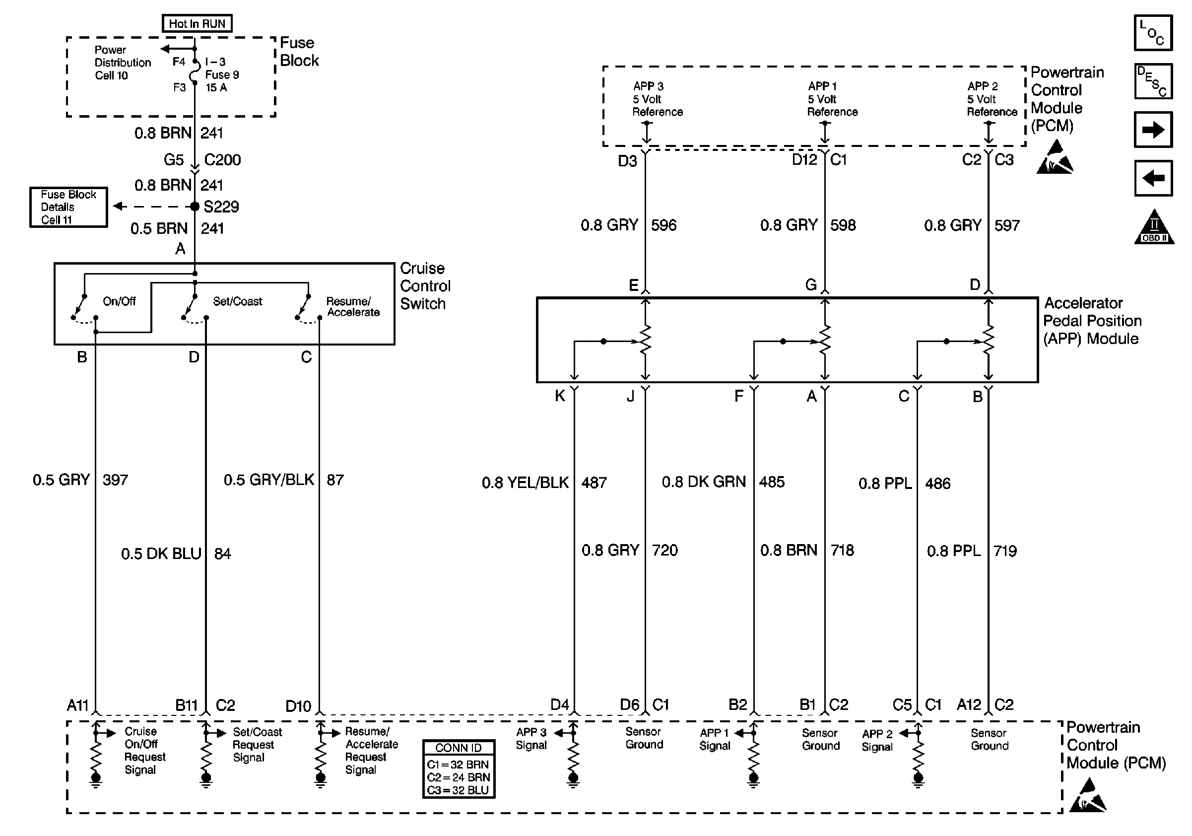
Cell 22: Accelerator Pedal Position Sensor, Cruise Switch Inputs
Cell 22: Engine Data Sensors and Wastegate Solenoid
OBD II Symbol Description Notice
Cell 11: ECM-I fuse [L65]
Cell 10: Ignition Switch and Fuse Block
P32 Cell 81 (3)
Handling ESD Sensitive Parts Notice
Figure
11:
Cell 22: Accelerator Pedal Position Sensor, Cruise Switch Inputs
Engine Controls Components
Information Sensors/Switches Description
Cell 22: A/T Controls 1 - Internal Solenoids, Brake Switches
Cell 22: VSS Circuit
OBD II Symbol Description Notice
Cell 10: Ignition Switch and Fuse Block
Handling ESD Sensitive Parts Notice
Figure
12:
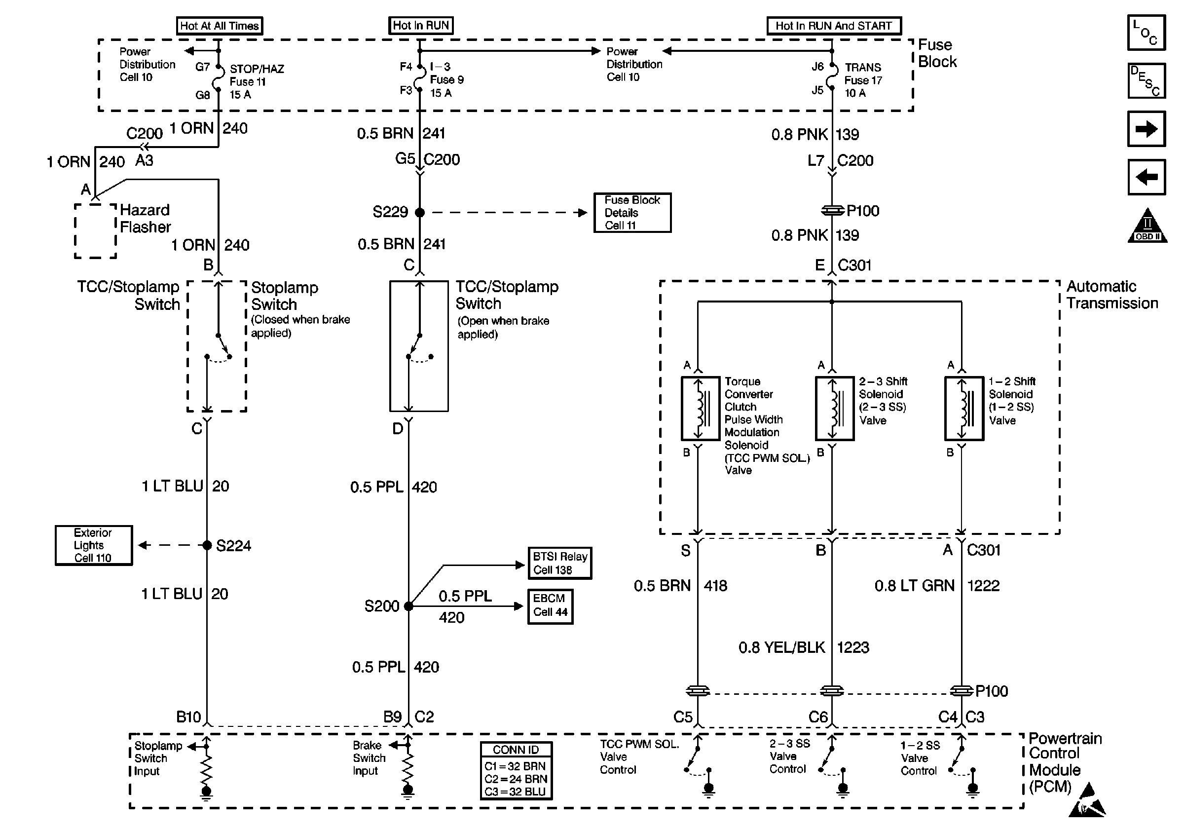
Cell 22: A/T Controls 1 -- Internal Solenoids, Brake Switches
Engine Controls Components
Electronic Component Description
Cell 22: A/T Controls 2 - TR Circuits, TFT, PC Sol. Valve, TISS
Cell 22: Accelerator Pedal Position Sensor, Cruise Switch Inputs
OBD II Symbol Description Notice
Cell 10: Fuse Block
Cell 10: Ignition Switch and Fuse Block
Cell 11: I-3, TURN-B/U, and HTR fuses, AUX CKT BRKR 13
Cell 10: Ignition Switch and Fuse Block
Handling ESD Sensitive Parts Notice
Cell 138: P42 BTSI Circuit
Cell 44: Diesel, ABS Power and Grounding, DLC Output
Cell 110: Turn Signal Switch
Figure
13:
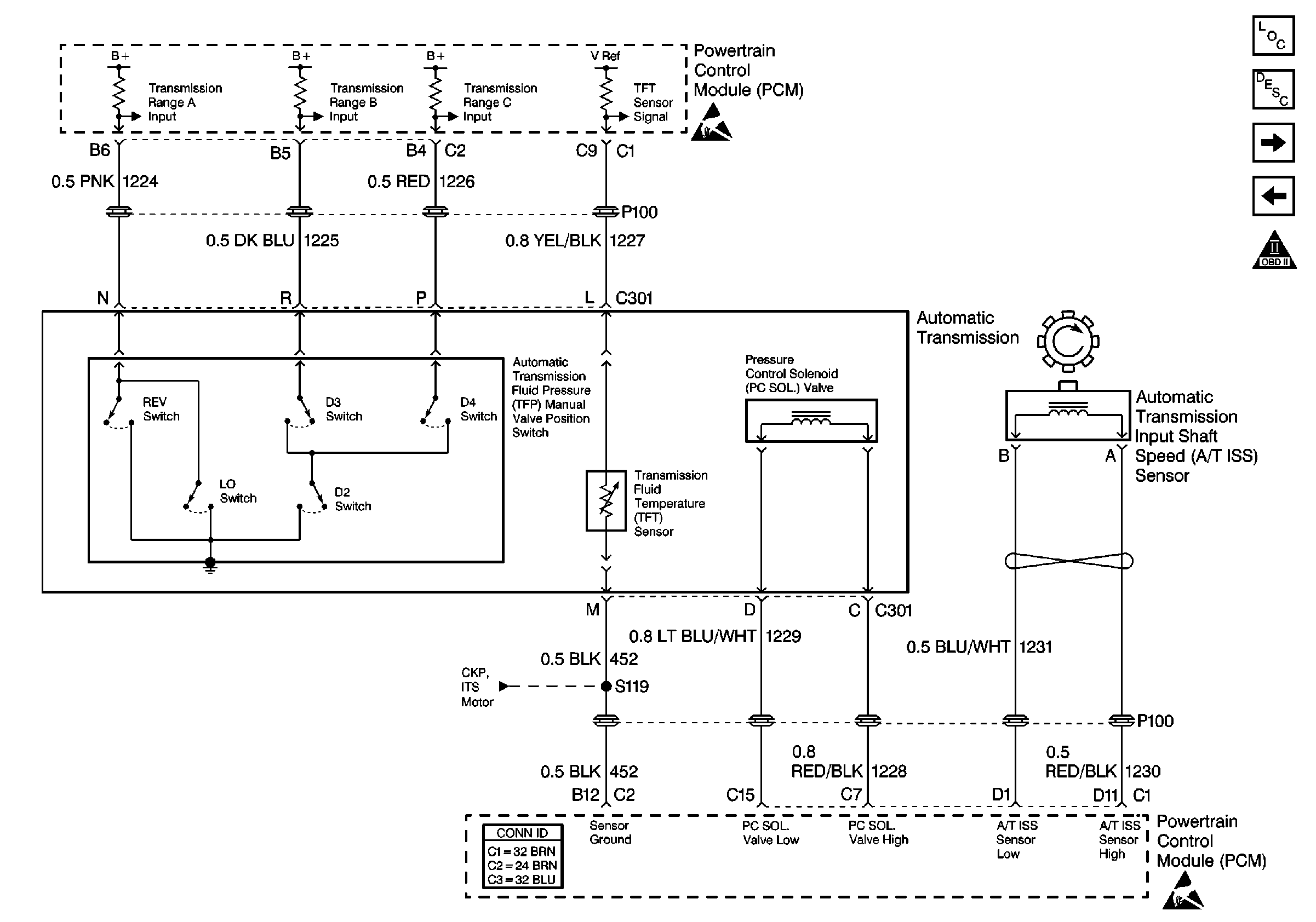
Cell 22: A/T Controls 2 -- TR Circuits, TFT, PC Sol. Valve, TISS
Engine Controls Components
Electronic Component Description
Cell 22: Air Conditioning Controls
Cell 22: A/T Controls 1 - Internal Solenoids, Brake Switches
OBD II Symbol Description Notice
Handling ESD Sensitive Parts Notice
Cell 22: Engine Data Sensors and Wastegate Solenoid
Figure
14:
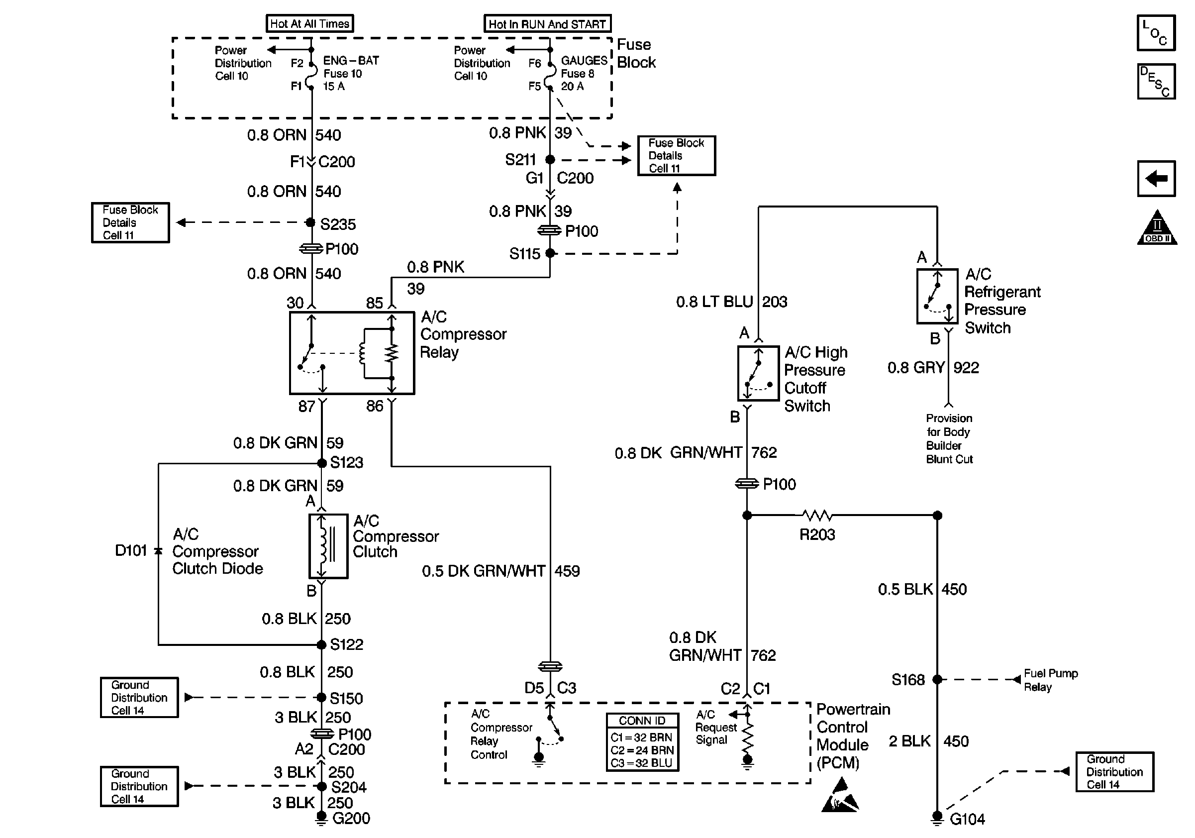
Cell 22: Air Conditioning Controls
Engine Controls Components
Relays and Sensors Description
Cell 22: A/T Controls 2 - TR Circuits, TFT, PC Sol. Valve, TISS
OBD II Symbol Description Notice
Cell 11: ENG-BAT and ECM-BAT fuses
Cell 10: Fuse Block
Cell 10: Ignition Switch and Fuse Block
Cell 11: GAUGES and TRANS fuses
Cell 22: Fuel Pump Controls
Cell 14: G104, G105, G106, and G110 [L65]
Handling ESD Sensitive Parts Notice
Cell 14: G200
Cell 14: S150 and S101 [L65]