Rotor Tolerance and Surface Finish
During the manufacture of the brake rotor, tolerances of the braking surfaces for flatness, parallelism and lateral runout are closely held. The maintenance of close tolerances on the shape of the braking surfaces is necessary in order to prevent brake roughness or pulsation.
In addition to these tolerances, the surface finish must be held to a specified range of 60 Ra roughness or less. The control of the braking surface finish is necessary in order to avoid problems of hard pedal application, excessive brake fade, brake and steering pulls, and erratic performance. Also, control of the surface finish can improve lining life.
Light scoring of the rotor surfaces not exceeding 1.5 mm (0.06 in) in depth is normal and is not detrimental to the brake operation.
Thickness Variation Check

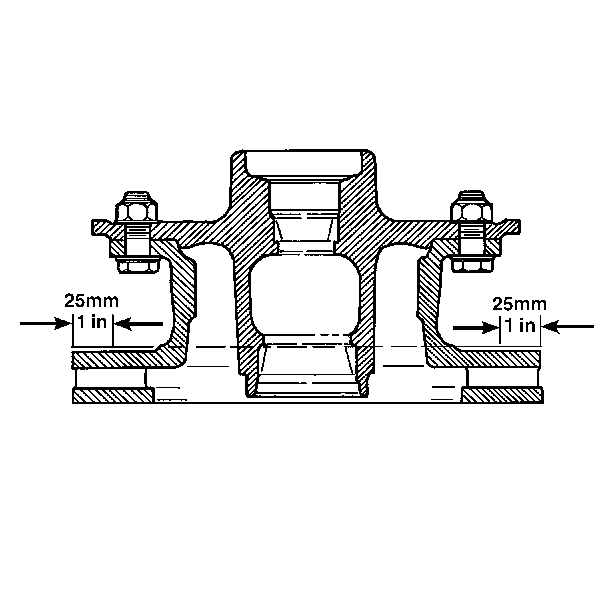
Check the thickness variation by measuring the rotor thickness at four or more points around the circumference of the rotor. Use a micrometer calibrated in ten-thousandths of an inch. Make all the measurements about 25 mm (1 in) in from the edge of the rotor.
A rotor that varies in thickness by more than 0.05 mm (0.002 in) can cause pedal pulsation and/or front end vibration during brake application. A rotor than does not meet these specifications should be refinished to specifications or replaced.
Lateral Runout Check

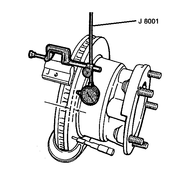
The best way to check the lateral runout is with the wheels still installed on the vehicle. This gives a much more accurate reading of the total indicated runout (T.I.R.) under real braking conditions. If equipment is not available to perform the check with the wheels installed, the next best reading can be made with the wheels removed but the caliper still installed.
- Clean the rotor surface.
- Tighten the wheel bearings to zero end play.
- Fasten a dial indicator to the steering knuckle so that the indicator button contact the rotor surface about 25 mm (1 in) from the outer edge.
- Set the dial indicator to zero.
- Turn the wheel one complete revolution. Observe the runout indicated on the dial.
- The total indicated runout (T.I.R.) must not exceed 0.13 mm (0.005 in).
- Adjust the wheel bearings. Refer to Wheel Bearing Adjustment in Front Suspension.
Excessive lateral runout can sometimes be improved by indexing the rotor on the hub one or two bolt positions from the original position. If the lateral runout cannot be corrected by indexing the rotor, check the hub and bearing assembly for excessive lateral runout or looseness. If the hub and bearing assembly lateral runout exceeds 0.040 mm (0.0015 in), replace the hub and bearing assembly. If the lateral runout is not within specifications, refinish or replace the rotor as necessary.
NOTICE: Any time the brake rotor is separated from the wheel bearing flange, clean any rust or foreign material from the mating surfaces of the wheel bearing flange and the rotor. Failure to do so can result in increased lateral runout of the rotor and brake pulsation.
