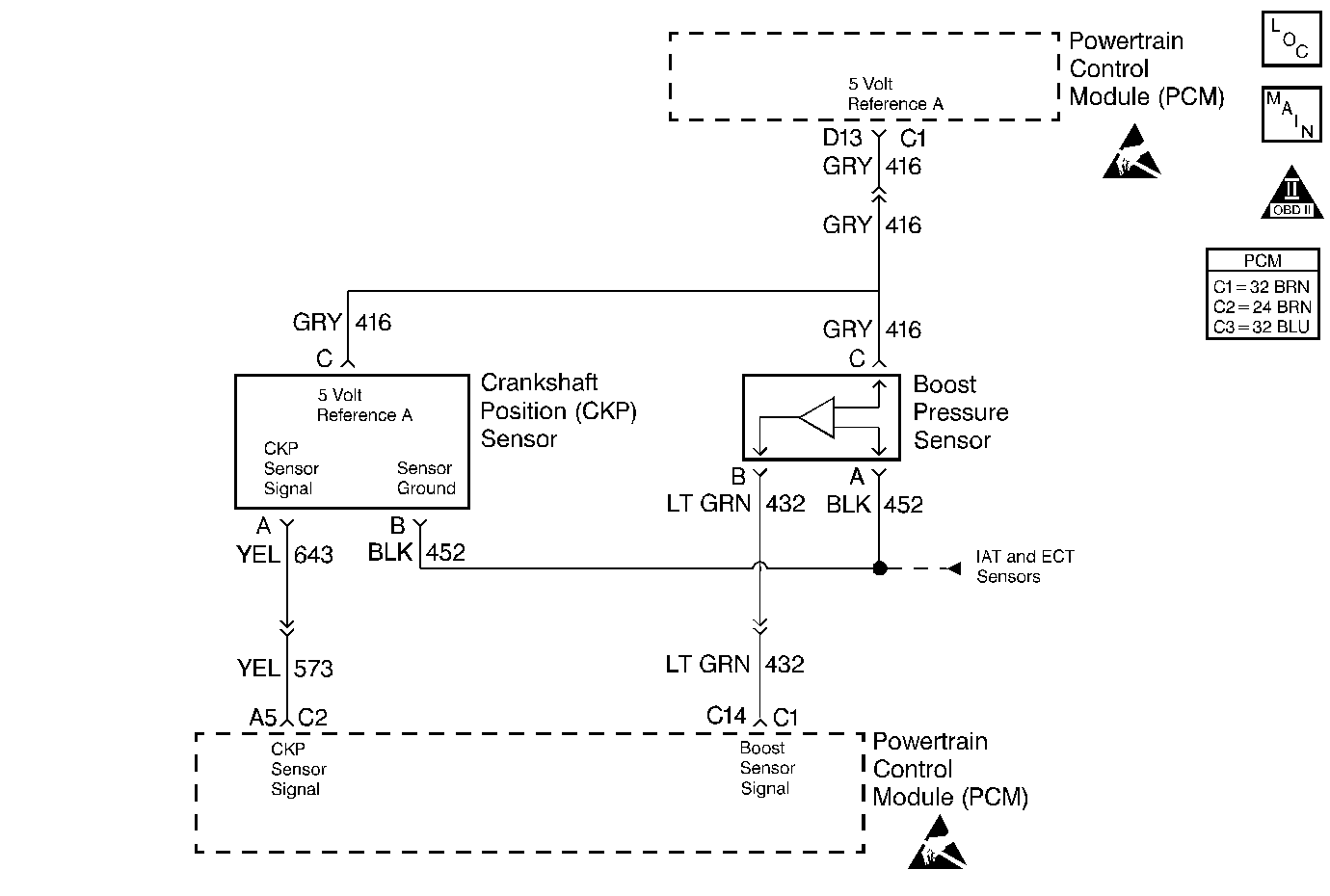
Circuit Description
The PCM operates a solenoid to control boost. This solenoid is normally open. By providing a ground path, the PCM energizes the solenoid which allows vacuum to pass to the wastegate valve. During normal operation, the PCM compares the wastegate duty cycle signal with the boost signal, and makes corrections to the duty cycle accordingly.
Conditions for Setting the DTC
| • | The Boost Pressure is less than 40 kPa. |
| • | The condition was met for 2 seconds. |
Action Taken When the DTC Sets
| • | The PCM illuminates the Malfunction Indicator Lamp (MIL) on the second consecutive drive trip the diagnostic runs and fails. |
| • | The PCM records the operating conditions at the time the diagnostic fails. The first time the diagnostic fails, the Failure Records store this information. If the diagnostic reports a failure on the second consecutive drive trip, the Freeze Frame records the operating conditions at the time of failure and updates the Failure Records. |
Conditions for Clearing the MIL/DTC
| • | The PCM will turn the MIL OFF after three consecutive trips without a fault condition. |
| • | A History DTC will clear after forty consecutive warm-up cycles during which the diagnostic does not fail (the coolant temperature has risen 5°C (40°F) from the start up coolant temperature and the engine coolant temperature exceeds 71°C (160°F) during that same ignition cycle). |
| • | Use of a Scan Tool will clear the DTC codes. |
Diagnostic Aids
Very little boost can be attained by revving the engine in neutral. If the boost sensor signal circuit is open or shorted to ground, the boost solenoid will show a zero duty cycle.
An intermittent may be caused by the following:
| • | Poor connections. |
| • | Rubbed through wire insulation. |
| • | Broken wire inside the insulation. |
Test Description
The numbers below refer to the step numbers on the Diagnostic Table.
-
This Step will determine if DTC P0237 is the result of a hard failure or an intermittent condition.
-
This Step simulates conditions for a DTC P0237. If the PCM recognizes the change, the PCM and the signal circuit are OK.
-
In this step, components that share the 5 volt reference can cause the reference voltage to be shorted to ground. This can be checked by disconnecting each component one at a time, including the PCM while checking for continuity on that circuit to chassis ground.
Step | Action | Value(s) | Yes | No |
|---|---|---|---|---|
1 |
Important: Before clearing any DTCs, use the Scan Tool Capture Info to save freeze frame and failure records for reference, as the Scan Tool loses data when using the Clear Info function. Was the Powertrain On-Board Diagnostic (OBD) System Check performed? | -- | Go to A Powertrain On Board Diagnostic (OBD) System Check | |
Does the J 39200 display a boost pressure less than or equal to the specified value? | 40 kPa | |||
Does the Scan Tool display a Boost Pressure greater than or equal to the specified value? | 202 kPa | |||
4 |
Does the Scan Tool display a Boost Pressure greater than or equal to the specified value? | 202 kPa | ||
5 | The DTC is intermittent. If no additional DTCs are stored, refer to Diagnostic Aids. If any additional DTCs are stored, refer to those tables first. Are there any additional DTCs stored? | -- | Go to the applicable DTC table | Go to Diagnostic Aids |
6 |
Was a problem found? | -- | ||
7 |
Was a problem found? | -- | ||
8 |
Was a problem found? | -- | ||
9 |
Was a problem found? | -- | ||
10 | Replace the boost sensor. Refer to Boost Sensor Replacement . Is the action complete? | -- | -- | |
11 |
Was a problem found? | -- | ||
12 | Replace the PCM. Important: The new PCM must be programmed. Refer to PCM Replacement/Programming . Is the action complete? | -- | -- | |
13 |
Does the Scan Tool indicate the diagnostic Passed? | -- | ||
14 | Does the Scan Tool display any additional undiagnosed DTCs? | -- | Go to the applicable DTC table | System OK |
