DIESEL HEAD GASKET LEAK SERVICE PARTS INFORMATION

To correct the early 1982 production head gasket coolant leakage condition, a new design head gasket entered production January 18, 1982.
For service, a revised service gasket is available.
Service Part Part Number
Cylinder Head Gasket 14061687
Cylinder Head Gasket Kit - Light Duty (Code "C") 14063783
Cylinder Head Gasket Kit - Heavy Duty (Code "J") 14063784
If a head gasket coolant leakage condition is encountered, check for the correct injection pump static timing setting as follows:
SERVICE INJECTION PUMP STATIC TIMING SETTING
Any service on the 6.2L diesel engine which requires replacement of the injection pump requires the static timing mark to be at the correct setting.
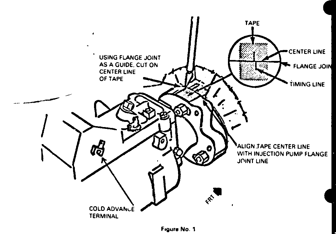
During the 1982 model year, a change to the procedure for marking the pump was made. Injection pumps built during the first half of the 1982 model prior to the change, required the pump timing mark to be offset from the housing flange mark. To facilitate these setting, a piece of tape was used which had offset lines. By lining up the tape lines, the correct setting was achieved. White tape was used on light duty engines and yellow on heavy duty.
Since service pumps may be of a different vintage than the removed pump, the following must be adhered to for correct timing setting whenever installing a replacement injection pump:
1. All injection pumps have a model identification plate which is attached to the pump housing just below the throttle linkage. The plate includes the (1) model number, (2) serial number and (3) the part number (Figure 1).
2. Remove and install injection pump per service manual procedure.
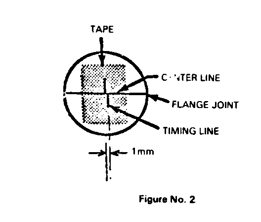
3. Refer to Figure 2 which displays the location of the timing marks which are stamped into the injection pump flange and the front housing.
4. Remove any timing tape that is over the stamped marks.
5. Refer to the model identification plate on the pump that is being installed. Use the following chart to determine the timing mark alignment setting:
Model Timing Mark Number Engine/RPO Pump P/N Offset
DB2-4090 Light Duty (LH6) 14050587 1.5mm DB2-4091 Heavy Duty (LL4) 14050588 2.5mm DB2-4126 Light Duty (LH6) 14050587 Aligned DB2-4153 Heavy Duty (LL4) 14050588 Aligned
6. If the pump is a DB2-4090 or 4091 always have the mark on the pump towards the left side (driver's) of the mark on the housing. This is the advance direction.
7. If an injection pump is to be removed and then reinstalled, it should be first paint marked at the pump to housing flange to allow reinstallation at the original setting.
8. Do not make timing adjustment with the engine running. Do not start engine until pump attaching nuts are torque securely.
Use applicable labor operation and time.


General Motors bulletins are intended for use by professional technicians, not a "do-it-yourselfer". They are written to inform those technicians of conditions that may occur on some vehicles, or to provide information that could assist in the proper service of a vehicle. Properly trained technicians have the equipment, tools, safety instructions and know-how to do a job properly and safely. If a condition is described, do not assume that the bulletin applies to your vehicle, or that your vehicle will have that condition. See a General Motors dealer servicing your brand of General Motors vehicle for information on whether your vehicle may benefit from the information.
