CAMPAIGN: FUEL TANK VENTING INSTALL FUEL TANK VENT

Models: 1985-87 Winnebago Motorhomes built on P3 Model Chassis Equipped with 7.4L (LE8) and H5D/NA5 Emissions
DEFECT INVOLVED:
The Winnebago Motorhome company has determined that a defect which relates to motor vehicle safety exists in some winnebago Motorhomes built on 1985-87 P3 Model chassis equipped with GM fuel tank systems and 7.4L (LE8) heavy duty emission gasoline engines (H5D/NA5).
These vehicles could emit gasoline from the fuel filler opening when the fuel fill cap is being removed. Such condition is more likely to occur when the vehicle operates in high temperature conditions, when the main fuel tank is overfilled and/or when fuel is first used from the auxiliary fuel tank after refueling both tanks. The condition results when the contents of the main fuel tank expand and the pressure in such tank increases. Should an ignition source be present, the escaping gasoline could ignite and cause a fire. Personal injury and/or vehicle damage may result.
To prevent this condition from occurring it will be necessary to install a new fuel tank vent assembly on vehicles equipped with a GM installed fuel tank.
VEHICLES INVOLVED:
Owners of these vehicles will be notified by Winnebago.
FUEL TANK INSTALLATIONS
Not all of the involved units are equipped with GM fuel tank installations. It is estimated that approximately 8-1/2% of the vehicles will be equipped with a Winnebago installed fuel tank.
GM installs as standard a 40 gallon fuel tank. An optional 60 gallon capacity fuel tank (RPO NN4) is offered. In certain instances, Winnebago will install a 30 gallon tank in addition to the GM 60 gallon tank.
In the above cases, the campaign modification must be made to vehicles which are equipped with GM fuel tanks. Vehicles equipped solely with Winnebago fuel tank(s) will not require campaign modifications.
Winnebago installs fuel tank similar to the way GM installs fuel tanks. The difference is in the number of fuel tank straps. Where GM uses two (2) fuel tank straps, Winnebago uses three (3) or more fuel tank straps. In addition, Winnebago does not use the fuel tank strap rubber insulator.
DEALER CAMPAIGN RESPONSIBILITY:
Dealers are to service all vehicles subject to this campaign at no charge to owners, regardless of mileage, age of vehicle, or ownership, from this time forward.
Whenever a vehicle subject to this campaign is taken into your new or used vehicle inventory, or it is in your Dealership for service in the future, you should take the steps necessary to be sure the campaign correction has been made before reselling or releasing the vehicle.
CAMPAIGN PROCEDURE:
Refer to Section 4 of the Service Policies and Procedures Manual for the detailed procedure on handling Product Campaigns. Dealers are requested to complete the campaign on all transfers as soon as possible.
OWNER NOTIFICATION: Winnebago will notify owners.
PARTS INFORMATION:
Parts required should be ordered through the Parts Department.
Part Number Description Quantity ----------- -------------------- -------- 15613507 Fuel Tank Venting Kit 1
Kit Consists of: 15613508 Vent Valve Bracket & Hose Asm 15613509 Hose & Tee Asm 2042292 Clamp - 8 Req'd 11509126 Tapping Screw - 8 Req'd 2002878 Tie Band - 2 Req'd 15613490 Label - Fuel Cap Removal 15613491 Label - Fuel Overfill 15613510 Instruction - Fuel Tank Vent 15613492 Instruction - Fuel Tank Overfill Warning Label
PARTS AND LABOUR CLAIM INFORMATION:
Credit for the campaign work performed will be paid upon receipt of a properly completed campaign claim card, RAPID terminal or DCS transmission in accordance with the following:
Repair Code Description Time Allowance --------- ----------------- -------------- 1A Inspect vehicle - not .3 hrs. equipped with factory installed fuel tank. No further action required.
2A Inspect vehicle and install .8 hrs. fuel tank vent assembly.
Time allowance includes 0.1 hour for Dealer administrative detail associated with this campaign. Parts credit will be based on Dealer net plus 30% to cover parts handling.
LABEL PLACEMENT PROCEDURE:
This service kit contains three labels, one large label 200mm x 40mm and two small labels 125mm x 31mm. Affix these labels to the vehicle using the following instructions.
- All surfaces that the labels will be affixed to must be clean and dry.
- On all vehicles, affix the large label onto the driver's sunvisor adjacent to the transit caution label so that it is visible by the driver when the sunvisor is in the down position.
- On all vehicles, affix one of the small labels onto the area just below the main tank fuel filler neck so that it is visible when the fuel filler neck door is open.
- On all vehicles equipped with an auxiliary tank, affix the second small label onto the same area of the filler neck that serves the auxiliary tank.
- If the vehicle is not equipped with an auxiliary tank, discard the second small label.
SERVICE PROCEDURE:
Disconnect negative battery cable.
Lift and support vehicle.
INSPECTION:
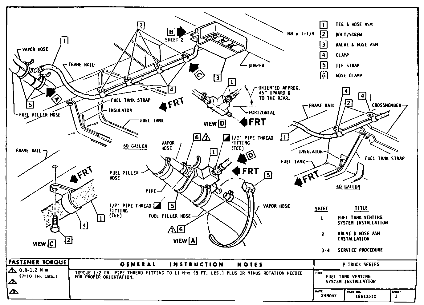
------------ Inspect fuel tank to determine if it has been installed by General Motors. A production installed tank of 40 or 60 gallon capacity will be attached to the chassis with two straps and insulators. The 40 gallon tank is secured to two rear crossmembers and the 60 gallon tank is secured to the frame rails, Sheet 1. If it is found that the vehicle has either one of these fuel tanks, a valve assembly must be inserted into the fuel vapour hose to exhaust gasoline vapours. Installation instructions for the valve and its mounting bracket are described below. If the vehicle has a fuel tank which was installed by a bodybuilder, the vehicle does not require modification.
SERVICE PROCEDURE:
- Looking up at the underside of the vehicle, locate the fuel filler hose and the fuel vapour hose. These hoses, 1 3/4 in. and 5/8 in. respectively, can be found together near the fuel filler neck.
- Cut the 5/8 in. fuel vapour hose and insert tee and hose assembly (1), Sheet 1. The centreline of the tee should be located at the connection between the fuel tank fill pipe and fill hose closest to the fuel tank (Sheet 1 View A) . The tee should be pointed upward. Tighten hose clamps [6] to 0.8-1.2 N.m (7-10 lbs. in.) and secure the tee assembly with tie strap [5] as required to hold it in place, Sheet 1.
- Every 12 to 15 in. down the bottom of the left hand frame rail drill a 9/32 hole, Sheet 1. Care must be used when drilling so that other vehicle components or wiring harnesses are not damaged.
- Use clamp [4] and screw [2] route 5/8 in. hose along the bottom of the frame rail to the bumper, Sheet 1. The hose must not sag or be restricted in any manner.
The trailer hitch mounting support to the left hand frame rail must be notched to route the vapour hose to the rear of the vehicle.
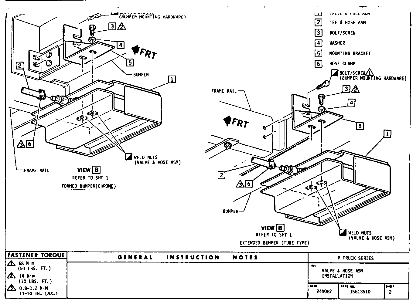
- Loosen the two bumper mounting bolts, left hand side of vehicle, at the end of the frame rail, Sheet 2.
- Slide mounting bracket [5], Sheet 2, under loosened bumper mounting bolts, retighten bolts to 68 N.m (50 lbs.ft.).
- Mount valve and hose assembly [1] to mounting bracket [5], Sheet 2. The slotted holes in the valve and hose assembly top cover must be beyond the Motorhome body for vehicles equipped with a tube type bumper, and beyond the bumper face for vehicles equipped with a chrome bumper. Tighten bolt [3] to 14 N.m (10 lbs.ft.).
- Trim 5/8 in. hose, part of tee and hose assembly [2], and connect to the valve and hose assembly [1], Sheet 2. Tighten hose clamp. (Ref sheet 1 [6] to 0.8-1.2 N.m (7-10 lbs. in.) Hose should not sag or be restricted in any manner.
- Lower vehicle.
- Reconnect batteries.
INSTALLATION OF CAMPAIGN IDENTIFICATION LABEL
Clean surface of radiator upper mounting panel and apply a Campaign Identification Label. Make sure the correct campaign number is inserted on the label. This will indicate that the campaign has been completed.


General Motors bulletins are intended for use by professional technicians, not a "do-it-yourselfer". They are written to inform those technicians of conditions that may occur on some vehicles, or to provide information that could assist in the proper service of a vehicle. Properly trained technicians have the equipment, tools, safety instructions and know-how to do a job properly and safely. If a condition is described, do not assume that the bulletin applies to your vehicle, or that your vehicle will have that condition. See a General Motors dealer servicing your brand of General Motors vehicle for information on whether your vehicle may benefit from the information.
