CAMPAIGN:AUTO APPLY PARKING BRAKE MALFUNCTIONS

Subject: PRODUCT SAFETY CAMPAIGN 90-C-50(a) - AUTO-APPLY PARKING BRAKE MALFUNCTIONS ---------------------------------------------------------
Model and Year: 1990 P30 MOTOR HOME CHASSIS WITH 16,000 GVW, AUTO-APPLY PARKING BRAKE AND 178" OR 208 WHEEL BASE -------------------------------------------------------
To: All Chevrolet/Geo Dealers
THIS REVISED CAMPAIGN BULLETIN IDENTIFIES THE PART NUMBER AND LABOR TIME FOR THE NEW LONGER RELAY VALVE INLET PIPE ASSEMBLY. MOTOR HOME OWNERS WHO PREVIOUSLY BROUGHT THEIR VEHICLE IN FOR THIS CAMPAIGN, AND THEIR VEHICLE NEEDS THIS LONGER HOSE, SHOULD BE CONTACTED AND A SERVICE DATE ARRANGED. MOTOR HOMES THAT HAVE HAD BODY TO CHASSIS HEIGHT MODIFICATIONS OR HAVE HAD THE RELAY VALVE RELOCATED MAY ALSO REQUIRE THIS NEW LONGER HOSE. ALL COPIES OF 90-C-50 SHOULD BE DESTROYED.
The National Traffic and Motor Vehicle Safety Act, as amended, provides that each vehicle which is subject to a recall campaign of this type must be adequately repaired within a reasonable time after the owner has tendered it for repair. A failure to repair within sixty (60) days after tender of a vehicle is prima facie evidence of failure to repair within a reasonable time.
If the condition is not adequately repaired within a reasonable time, the owner may be entitled to an identical or reasonably equivalent vehicle at no charge or to a refund of the purchase price less a reasonable allowance for depreciation.
To avoid having to provide these burdensome solutions, every effort must be made to promptly schedule an appointment with each owner and to repair their vehicle as soon as possible. As you will see in reading the attached copy of the letter that is being sent to owners, the owners are being instructed to contact the Chevrolet Customer Assistance Center if their dealer does not remedy the condition within five (5) days of the mutually agreed upon service date. If the condition is not remedied within a reasonable time, they are instructed on how to contact the National Highway Traffic Safety Administration.
DEFECT INVOLVED
General Motors has determined that a defect which relates to motor vehicle safety exists in certain 1990 P30 Motor Home Chassis. If there is a fluid leak in the auto-apply hydraulic parking brake system the parking brake may apply while the vehicle is being driven. The "BRAKE" telltale would come on and there would be a noticeable drag when driving. Under these circumstances, there would also be no loss of control of the vehicle, and the driver should pull the vehicle off the road and seek proper service. If the driver ignores the "BRAKE" telltale and continues to drive with the parking brake applied, the parking brake system subsequently could fail. If the driver then attempted to park the vehicle and released the brake pedal, the motor home could roll. However, the brake pedal could still be applied by the driver to prevent the motor home from rolling.
To correct this condition, dealers must follow the procedure contained in this bulletin and install an Auto-Apply Park Brake System Service Kit, bleed the hydraulic power system, and adjust the parking brake
VEHICLES INVOLVED
Involved are certain 1990 Chevrolet P30 Motor Home chassis vehicles equipped with 16,000# GVW (RPO C7P), auto-apply parking brake, and 178" or 208" wheel base. Involved vehicles were built within the following VIN breakpoints:
PLANT YEAR MODEL PLANT CODE FROM THROUGH ---- ------ ----- ----- ---- -------
1990 P30 Motor Home Chassis Detroit "3" L3300317 L3324370
Involved vehicles have been identified by Vehicle Identification Number Computer Listings. Computer listings contain the complete Vehicle Identification Number, owner name and address data, and are furnished to involved dealers with the campaign bulletin. Owner name and address data furnished will enable dealers to follow-up with owners involved in this campaign.
These listings may contain owner names and addresses obtained from State Motor Vehicle Registration Records. The use of such motor vehicle registration data for any other purpose is a violation of law in several states. Accordingly, you are urged to limit the use of this listing to the follow-up necessary to complete this campaign. Any dealer not receiving a computer listing with the campaign bulletin has no involved vehicles currently assigned.
PARTS INFORMATION
Kits required to complete this campaign are to be obtained from General Motors Service Parts Operations (GMSPO. To ensure these parts will be obtained as soon as possible, they should be ordered from GMSPO on a "C.I.O." order with no special instruction code, but on an advise code (2).
Quantity/ Part Number Description Vehicle ----------- ----------- ---------
12380411 Auto-Apply Parking Brake Service Kit 1 12345867 Power Steering Fluid As Required 26052241 Relay Valve Inlet Pipe Assembly As Required
THE FOLLOWING PARTS ARE INCLUDED IN THE SERVICE KIT:
* Cable Clip * Cable Washer * Power Steering Reservoir Cap * Power Steering Vent Overflow Hose * Power Steering Vent Overflow Hose Clamp * Parking Brake Brace * Bolts 1/4" 20 x 2.00" (GM 280-M) - Qty.2 * Nuts 1/4"-20 (GM 286M) Qty.2 * Valve Seal Repair Kit * Manual Control Supply Hose * Relay Valve Inlet Pipe Assy. * Park Brake Operation Label * Label Installation Sheet * Instruction Sheet
OWNER NOTIFICATION
Owners will be notified of this campaign on their vehicles by Chevrolet Motor Division (see copy of owner letter included with this bulletin).
DEALER CAMPAIGN RESPONSIBILITY
All unsold new vehicles in dealers' possession and subject to this campaign must be held and inspected/repaired per the service procedure of this campaign bulletin before owners take possession of these vehicles.
Dealers are to service all vehicles subject to this campaign at no charge to owners, regardless of mileage, age of vehicle, or ownership, from this time forward.
Owners of vehicles recently sold from your new vehicle inventory with no owner information indicated on the dealer listing, are to be contacted by the dealer, and arrangements made to make the required correction according to the instructions contained in this bulletin. This could be done by mailing to such owners a copy of the owners letter accompanying this bulletin. Campaign follow-up cards should not be used for this purpose, since the owner may not as yet have received the notification letter.
In summary, whenever a vehicle subject to this campaign enters your vehicle inventory, or is in your dealership for service in the future, please take the steps necessary to be sure the campaign correction has been made before selling or releasing the vehicle.
GENERAL INFORMATION
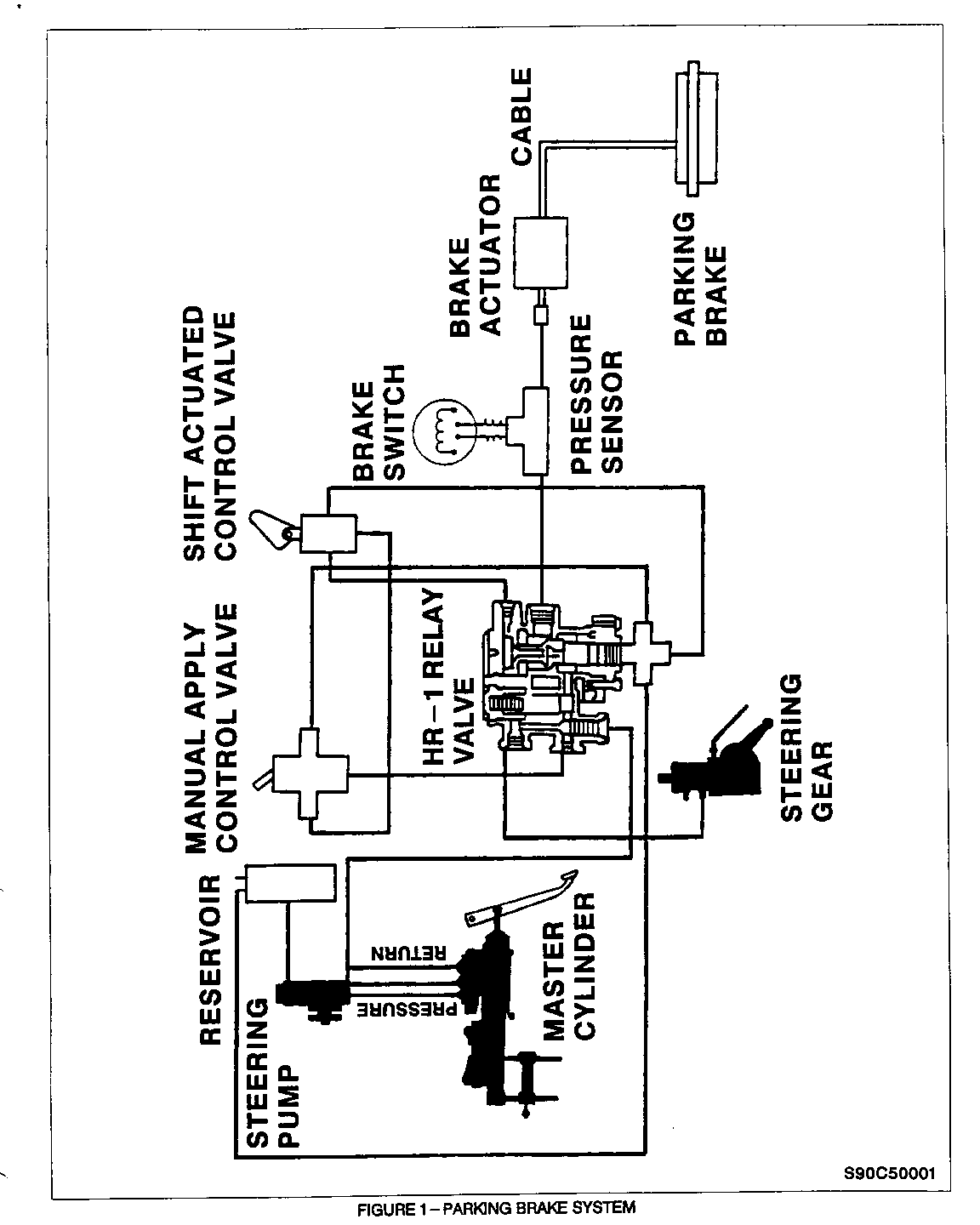
The parking brake system on the 1990 Chevrolet P30 Motor Home chassis with 16,000# GVW (Gross Vehicle Weight) incorporates a unique automatic apply feature with an expanding parking brake. The parking brake is spring applied and hydraulically released. Hydraulic pressure is supplied by the power steering pump. Full brake disengagement requires that 95 to 115 PSI pressure exists at the brake actuator.
The parking brake can be applied by using a hand button or automatically when the shift lever is in the "park" position. The system features an HR-1 relay valve serving as a flow control point. The HR-1 reduces and directs flow to and from a spring actuator operating the park brake (see Figure 1, Page 5).
OPERATIONAL FEATURES
In the event the vehicle stalls, the wheels can be spun freely for at least ten minutes until the pressure is drained from the brake actuator and the spring brake reapplies.
A parking brake light in the vehicle warns the operator when the pressure at the actuator is less than 60 PSI.
SERVICE PROCEDURE
DIAGNOSTIC INFORMATION
Diagnostic charts in Truck Service Bulletin Corporate Number 065020, Chevrolet Number 90-391-5, Group 5-Brakes, dated October, 1990 can be used to determine if the auto-apply parking brake system is functioning normally and to identify what repairs may be required. The bleed procedures in Corporate Number 065020 Bulletin have been revised. A corrected bleed procedure is provided later in this bulletin. Additionally, Bulletin 90-391-5 incorporates information on replacement and bleed procedure of the HR-1 Relay Valve. However, this information is NOT needed to perform the Service Procedure in this bulletin. It is mentioned for future reference material only.
REPAIR PROCEDURE
Notice: Wear Safety Glasses, personal injury could occur.
Exhaust manifold may be hot, allow to cool prior to performing repairs.
1. Place column shift selector lever in "park", turn ignition key to "off" position, do not apply manual parking brake. Block wheels to prevent vehicle movement during servicing.
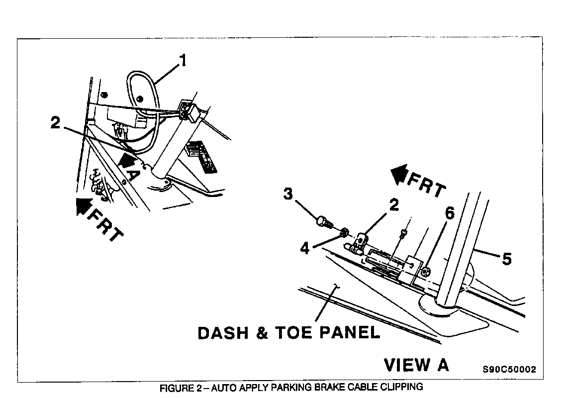
2. From inside vehicle, locate parking brake control cable Figure 2, 1) located under the instrument panel adjacent to steering column and cable clip (Figure 2, 2) (at floor).
3. Remove cable clip nut (Figure 2, 6) and bolt (Figure 2, 3) and washer(s) (Figure 2, 4). Washer(s) will not be reused. Retain the bolt and nut for reinstallation procedure.
4. Remove cable clip (Figure 2, 2) from cable (Figure 2, 1). Cable clip will not be reused. Utilizing a new clip, attach cable to bracket using existing bolt and nut and a new washer. Align clip to prevent possible kinks in cable from occurring during tightening of bolt and nut.
5. Torque nut (Figure 2, 6) to 6-9 Nm (5-7 lb. ft.).
6. Safely vent exhaust and start engine. Put column shift selector lever in "neutral" position and set manual parking brake. Release parking brake control and observe that light on dash goes out. Reapply parking brake control and observe that parking brake actuates. Also verify that parking cable operates smoothly.
7. Replace power steering reservoir cap with a new vented cap. Cut new vent overflow hose length to approximately 870 mm (34 1/4") and install to reservoir cap using new fastening clamp. Route vent overflow hose across and under fuse box, behind washer bottle and downward in front of driver's side wheel well.
8. Raise vehicle following all safety precautions. If a hoist is not available, raise front axle and use suitable safety stands.
9. Place column selector lever in "park" position, turn engine to Off" position and set manual parking brake.
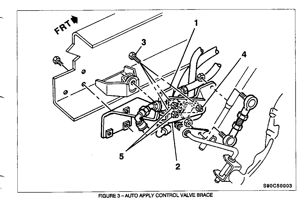
10. Locate parking brake control valve (Figure 3, 1) on left inside frame rail adjacent to transmission shift control.
11. Remove three parking brake control valve brace bolts (Figure 3, 3 and 4). Two (2) 1/4" nuts (Figure 3, 5), bolts (Figure 3, 3) and all three (3) washers will not be reused. Retain 5/16" bolt and nut (Figure 3, 4).
12. Install a new brace (Figure 3, 2) towards transmission on parking brake control valve so that brace faces inboard. Install brace using two (2) new 1/4" bolts (Figure 3, 3) and new nuts (Figure 3, 5) in rear holes of brace. Reinstall existing 5/16" bolt and nut Figure 3, 4) in forward hole.
Notice: Nuts and bolts must be installed as shown in Figure 3 with nuts clamping against new brace.
13. Torque all three (3) nuts (Figure 3, 4 and 5) to 6-9 Nm 5-7 lb. ft.).
14. With column shift lever in "park" position, start engine, release manual parking brake, and cycle the auto-apply parking brake system by moving column shift selector lever from "park" to "drive". Observe that vehicle's parking brake functions properly.
15. Place column shift selector lever back into "park", turn ignition to off" position and apply manual parking brake. Inspect parking brake control valve for any hydraulic leaks. Torque fittings as required.
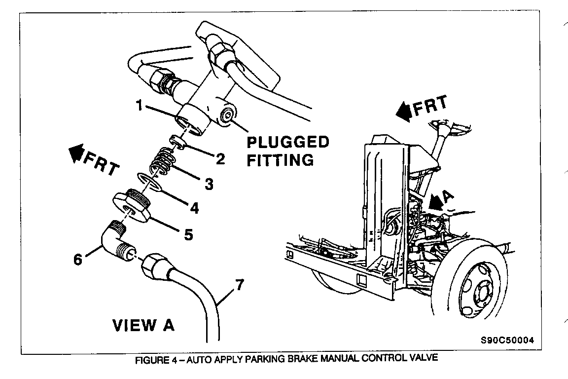
16. Remove left front inner wheel well panel. Retain all fasteners and panel for reinstallation process. Pin-point manual control valve (Figure 4, 1) located above relay valve that is located above the hydro-boost unit. Prepare removal area by having a catch pan and/or towels/rags available to catch any oil leakage from supply pipe/valve during removal.
17. Remove and discard supply pipe (Figure 4, 7) located between manual control valve (Figure 4, 1) and relay valve. Remove cap nut (Figure 4, 5) and elbow (Figure 4, 6) as an assembly. Remove inlet valve (Figure 4, 2) spring (Figure 4, 3) and 0-ring (Figure 4, 4). Inlet valve (Figure 4, 2) may not drop out due to oil viscosity; it may be necessary to use a thin pick to dislodge inlet valve (Figure 4, 2) from inside valve.
18. Prior to assembly, lubricate control valve bores (Figure 4, 1), 0-ring (Figure 4, 4) and cap nut threads (Figure 4, 5) with Lubriplate or equivalent. Install replacement 0-ring (Figure 4, 4) over replacement cap nut (Figure 4, 5); place spring (Figure 4, 3) on inner pocket of cap nut Figure 4, 5) and rest inlet valve (Figure 4, 2) on top of spring (Figure 4, 3). Balancing this assembly, gently raise into valve body. Upon making contact with valve, hand tighten assembly. Then torque cap nut (Figure 4, 5) to 6-15 Nm (5-12 lb. ft.) in proper alignment with supply pipe (improper assembly may result in an inoperative/noisy park brake).
Notice: Excessive torque of cap nut (Figure 4, View A, 5) may result in crushing of bottom portion of control valve.
19. Remove nut and compression fitting from replacement elbow assembly. Nut and fitting will not be reused. Apply thread sealant to threads going into new cap nut (Figure 4, 5) and threaded surface of new elbow (Figure 4, 6) . Thread elbow (Figure 4, 6) into cap nut (Figure 4, 5) and torque cap nut to 12-14 Nm (9-10 lb. ft.). Align elbow (Figure 4, 6) for reattachment to a new supply pipe.
Notice: DO NOT apply sealant over elbow opening.
20. Install new manual control supply hose (Figure 4, 7) between manual control valve and relay valve. Torque nuts to 12-14 Nm 9-10 lb. ft.).
21. Place column shift selector lever in "neutral" position. DO NOT apply manual parking brake. Turn ignition to "Off" position.
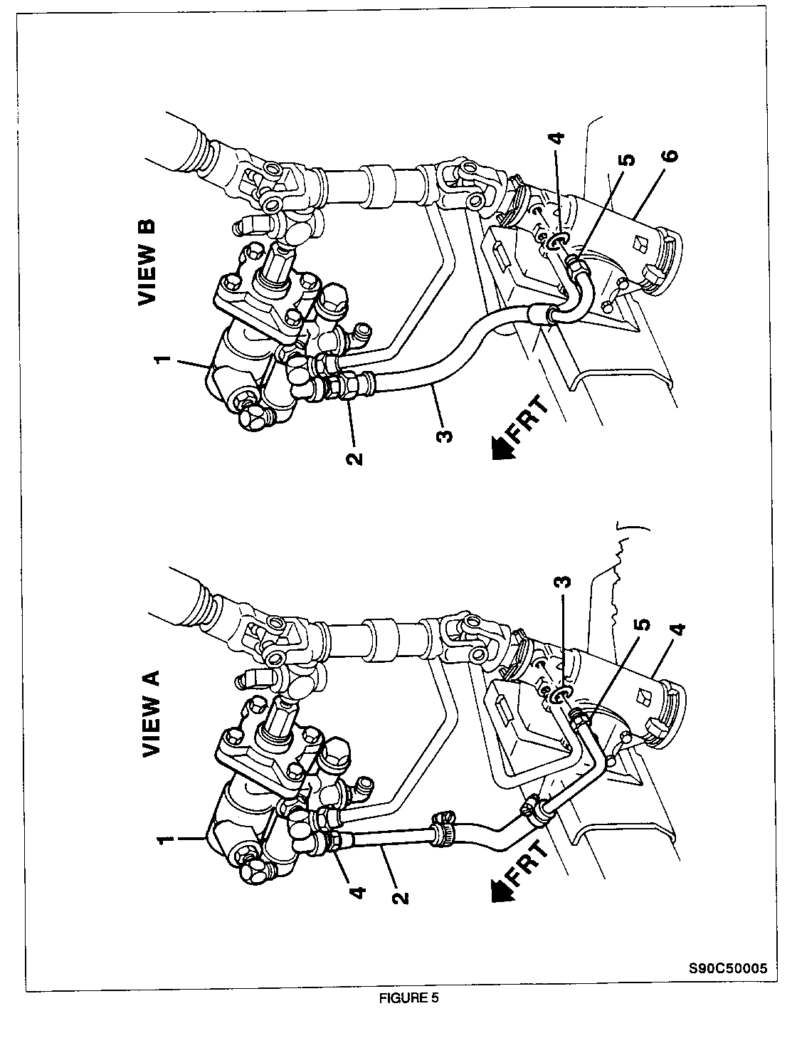
22. Locate relay valve assembly (Figure 5, 1) and steering gear relay valve inlet pipe assembly (Figure 5, 2) shown in Figure 5, View A. Prepare removal area by having a catch pan and towel/rags available to catch any oil leakage from hose during removal.
23. Refer to Figure 5, View A and remove relay valve inlet hose assembly (Figure 5, 2) at tube nut (Figure 5, 4) and steering gear nut (Figure 5, 5) . Catch as much fluid as possible. Remove 0-ring (Figure 5, 3) from steering gear.
Notice: THE NEW LONGER HOSE (PART NUMBER 26052241) MAY BE REQUIRED IF ANY OF THE FOLLOWING SITUATIONS APPLY:
- IF ANY ATTEMPT TO PERFORM THE ORIGINAL CAMPAIGN WAS MADE AND THE RELAY VALVE INLET PIPE ASSEMBLY WAS TOO SHORT.
- IF THE MOTOR HOME HAS HAD BODY TO CHASSIS HEIGHT MODIFICATIONS.
- IF THE RELAY VALVE HAS BEEN RELOCATED.
24. Refer to Figure 5, View B and install one end of new hose assembly (Figure 5, 3) at steering gear (Figure 5, 6) and carefully seat 0-ring (Figure 5, 4) into steering gear seat. Finger tighten steering gear nut (Figure 5, 5) . Install other end of hose assembly (Figure 5, 3) at relay valve (Figure 5, 1) and finger tighten tube nut (Figure 5, 2).
25. Refer to Figure 5, View B and torque steering gear nut (Figure 5, 5) at steering gear to 20-34 Nm (15-25 lb. ft.) and the tube nut (Figure 5, 2) at the relay valve assembly to 20-27 Nm (15-20 lb. ft.).
26. Bleed power steering system using the "Power Steering Bleed Procedure" contained later in this bulletin.
27. Adjust parking brake using the "Parking Brake Adjustment" procedure contained later in this bulletin.
28. Lower front of vehicle.
29. Install Campaign Identification Label.
POWER STEERING BLEED PROCEDURE
Notice: To maintain proper fluid level throughout bleed procedure, check and fill power steering reservoir with power steering fluid as necessary. Keep column shift selector ONLY in "PARK" position when filling
1. Place column shift selector lever in "park", turn ignition to Off" position.
2. Fill power steering pump fluid reservoir to proper level and let fluid settle for at least a few minutes.
3. Start engine. Let engine run for a few seconds; then turn off.
4. Add power steering fluid, if necessary.
5. Repeat steps 1 through 4 until fluid level remains constant after running engine.
6. Start engine and place column shift lever in "neutral". Do not apply manual parking brake and shut off engine after illuminated Brake" light goes off.
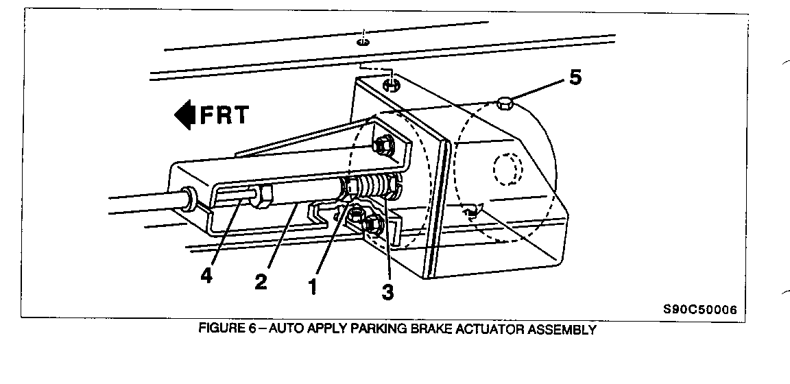
7. Remove bleed bolt (Figure 6, 5) located on top of parking brake actuator and bleed system.
8. Tighten actuator bleed bolt and cycle system by starting engine and applying manual park brake.
9. Repeat steps 6-8 until air is removed from system.
10. Turn off engine. Check fluid level and refill as required.
11. If fluid is extremely foamy, allow vehicle to stand a few minutes and repeat above procedure.
12. If air still remains in system, repeat Steps 6 through 11.
13. Pump brakes several times with engine off and column shift selector in "neutral" position.
14. Start engine with vehicle in "park". Slowly turn steering wheel right and left lightly contacting wheel stops. Shut engine off and check power steering fluid level. Add fluid if necessary.
15. Place column shift selector lever in "neutral" position and start engine. Engage parking brake using manual control valve.
16. Partially open upper exhaust fitting of manual control valve located above relay valve. Allow a small amount of fluid to bleed out of fitting, then quickly tighten fitting.
17. Repeat steps 15 and 16, as required.
18. After completion of bleeding procedure, reinspect hoses for any fluid leaks. Re-torque as required.
PARK BRAKE ADJUSTMENT
1. Place column shift selector lever in "neutral", turn manual parking brake to "off" position, and start and run engine until parking brake telltale lamp goes off.
2. Either raise and support rear axle with suitable safety stands or disconnect driveline shaft. Block front wheels.
3. To adjust brake-to-drum clearance, remove dust cover (plug) on parking brake drum. Turn drum to align access hole in drum with adjusting star wheel. Adjust star wheel through drum opening until brake just locks up. Back off star wheel two to four notches. When properly adjusted, drum should spin free with only light drag.
4. Inspect parking brake shoes and drum. Repair required.
5. If driveline shaft was disconnected, reconnect or lower rear axle.
6. To adjust cable free play place column shift selector lever in "neutral" position and start engine until brake light goes off, then shut engine off. Loosen jam nut (Figure 6, 1) towards brake actuator. Turn 5-inch-long hex nut (Figure 6, 2) along stud until no free play exists. Move jam nut (Figure 6, 1) until it is tight against 5-inch-long hex nut Figure 6, 2). Tighten safety nut (Figure 6, 3) against jam nut. When properly adjusted, actuator rod (Figure 6, 4) should stroke between .75 and 1.00 inch.
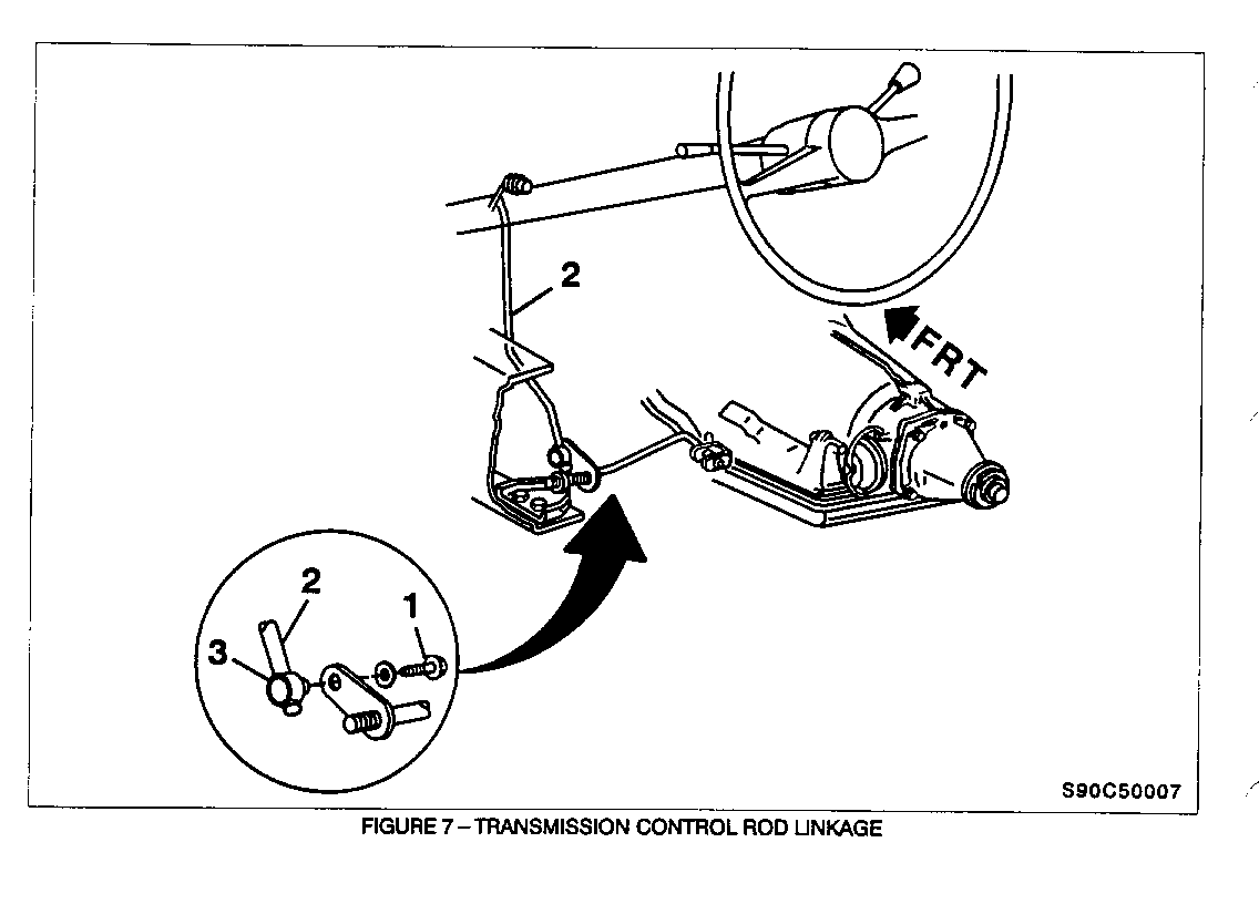
7. To adjust transmission linkage, apply manual parking break. Loosen screw (Figure 7, 1) on adjuster located at transmission. Place column selector lever in neutral position. On transmission, place transmission shift lever in "neutral", then move shift lever (Figure 7, 4) to forward position (past park) and back up to the third detent. Hold rod (Figure 7, 2) tightly in swivel (Figure 7, 3). Tighten screw (Figure 7, 1) to 23 Nm 17 lb. ft.) . Put column selector lever in "park" position. Check adjustment. Column selector lever must go into all positions. Engine must start in "park" or "neutral" positions only.
8. Check for proper operation of parking brake system and repair as required.
9. Reinstall inner wheel well panel.
10. Remove exhaust vent hose.
11. Remove wheel blocks.
12. Install Power Brake Operation label on sun visor.
CAMPAIGN IDENTIFICATION LABEL
Each vehicle corrected in accordance with the instructions outlined in this Product Campaign Bulletin will require a "Campaign Identification Label". Each label provides a space to include the campaign number and the five (5) digit dealer code of the dealer performing the campaign service. This information may be inserted with a typewriter or a ball point pen.
Each "Campaign Identification Label" is to be located on the radiator core support in an area which will be visible when the vehicle is brought in for periodic servicing by the owner. Additional "Campaign Identification Labels" can be obtained from DAC.
Apply "Campaign Identification Label" only on a clean, dry surface.
CLAIM INFORMATION
Submit a Product Campaign Claim with the information indicated below:
REPAIR FAILED PARTS LABOR LABOR OTHER NET PERFORMED PC PART NO. ALLOW CC-FC OP HOURS HOURS AMOUNT ---------- -- --------- ----- ----- ----- ----- ------ ------
Install Auto-Apply Parking Brake 1 12380411 ** SK-00 V9070 1.7 0.1 *** Service Kit
Install Longer Relay Valve Inlet 1 26052241 ** SP-95 T2409 0.6 -- -- Assembly
* Campaign Administrative Allowance.
** The "Parts Allowance" should be the sum total of the current GMSPO Dealer Net price plus 30% of all parts required for the repair.
*** The amount identified in the "Net Amount" column should represent the sum of the current GMSPO Dealer Net price plus 30% for power steering fluid used to perform the required repairs.
Refer to the Chevrolet Claims Processing Manual for details on Product Campaign Claim Submission.
General Motors bulletins are intended for use by professional technicians, not a "do-it-yourselfer". They are written to inform those technicians of conditions that may occur on some vehicles, or to provide information that could assist in the proper service of a vehicle. Properly trained technicians have the equipment, tools, safety instructions and know-how to do a job properly and safely. If a condition is described, do not assume that the bulletin applies to your vehicle, or that your vehicle will have that condition. See a General Motors dealer servicing your brand of General Motors vehicle for information on whether your vehicle may benefit from the information.
