AUTO APPLY PARKING BRAKE MAY NOT RELEASE

SUBJECT: AUTO APPLY PARKING BRAKE MAY NOT RELEASE
VEHICLES AFFECTED: 1990-91 P3 CHASSIS 16000 GVWR (REPLACE CLIP, WASHER AND OR BRACE)
Some 1990 - 1991 P3 Motorhomes with auto apply parking brake may not release. The cause may be loosening of the auto apply cable and/or the auto apply control valve. Follow the appropriate service procedure that addresses the condition.
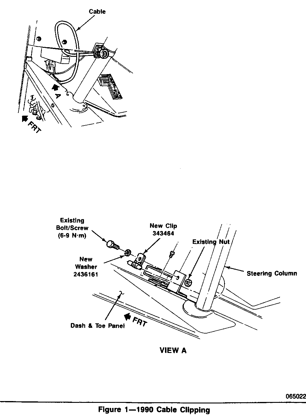
AUTO APPLY CABLE ON 1990-91 P3 16,000# MOTORHOMES WITH C7P ---------------------------------------------------------- The auto apply control cable may loosen or pull through the attaching clip. This loosening can be corrected by the replacement of the clip (2058447) and the installation of a new washer (2436161).
SERVICE PROCEDURE: Refer to Figure 1:
1. Place shift lever in park, turn ignition key to the off position. Block the wheels to prevent vehicle movement during servicing.
2. Locate the park brake control cable under the instrument panel adjacent to the steering column, as shown in Figure 1.
3. Remove the bolt holding the cable in place. Retain the bolt and nut for the reinstallation procedure.
4. Remove the cable clip from the cable and discard. Utilizing a new clip (P/N 343464) attach the cable to the bracket using the existing bolt and nut and a new washer (P/N 2436161). Align the clip so that no kinking of the cable occurs during the tightening of the bolt and nut as shown in Figure 1.
5. Torque the nut to 6 - 9 N.m. (4.5 to 6.6 ft.lbs.).
6. Start the engine. Verify the vehicle's transmission is in the neutral position and the "park brake" control is applied. Release the "park brake" control and observe that light on dash goes out. Reapply the "park brake" control and observe that park brake actuates. Also verify that park brake cable operates smoothly.
7. Return vehicle to holding area; service inspection work is completed.
SERVICE PARTS INFORMATION
Part Number Description Quantity ---------- ------------ ------------------------- 2436161 Washer 1 (all P30032 at 16,000 lb, Option C7P) 343464 Clip 1
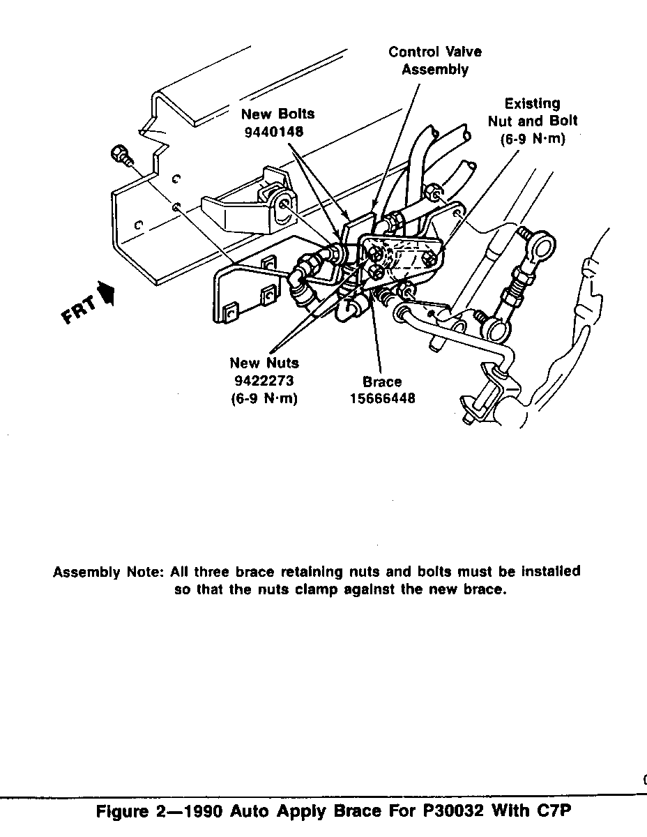
AUTO APPLY VALVE BRACE ON 1990 P3 16,000# MOTORHOMES WITH C7P -------------------------------------------------------------- The auto apply control valve may loosen at the cam actuator arm. This condition can be corrected by the installation of a brace, (P/N 15666448).
SERVICE PROCEDURE Refer to Figure 2:
1. Set parking brake, block wheels, ignition in the off position, and transmission in the park position.
2. Locate the park brake control valve on the left inside frame rail adjacent to the transmission shift control as shown in Figure 2.
3. Remove the three bolts shown in figure 2. Discard the washers; retain the 5/16" bolt and nut. Obtain two new nuts and bolts for the lower mounting attachment.
4. Install the new brace (P/N 15666448) towards the the transmission on the control valve so that the brace faces inboard. Install the two new lower bolts and nuts as shown. Reinstall the existing upper bolt and nut.
IMPORTANT: Nuts and bolts must be installed as shown in Figure 2 with the nuts clamping against the new brace.
5. Torque the two 1/4" nuts and the 5/16" nut to 6 - 9 N.m. (4.5 to 6.6 ft.lbs.).
6. With the vehicle in the park position, remove the wheel blocks, start the engine, release the manual park brake, and cycle the auto park apply system by moving the shift lever from park to drive. Observe that the vehicle's park brake functions properly.
7. Turn off vehicle; put on parking brake; shift lever in park; inspect the control valve for any hydraulic leaks; torque fitting as required.
SERVICE PARTS INFORMATION
Part Number Description Quantity ---------- ---------------- ---------------------------- 15666448 Brace Park Brake 1 (all P30032 at 16,000, Control valve option C7P)
9440148 Bolt 1/4"-20 X 2.00" 2 (GM 280-M)
9422273 Nut 1/4"-20 2 (GM 286-M)
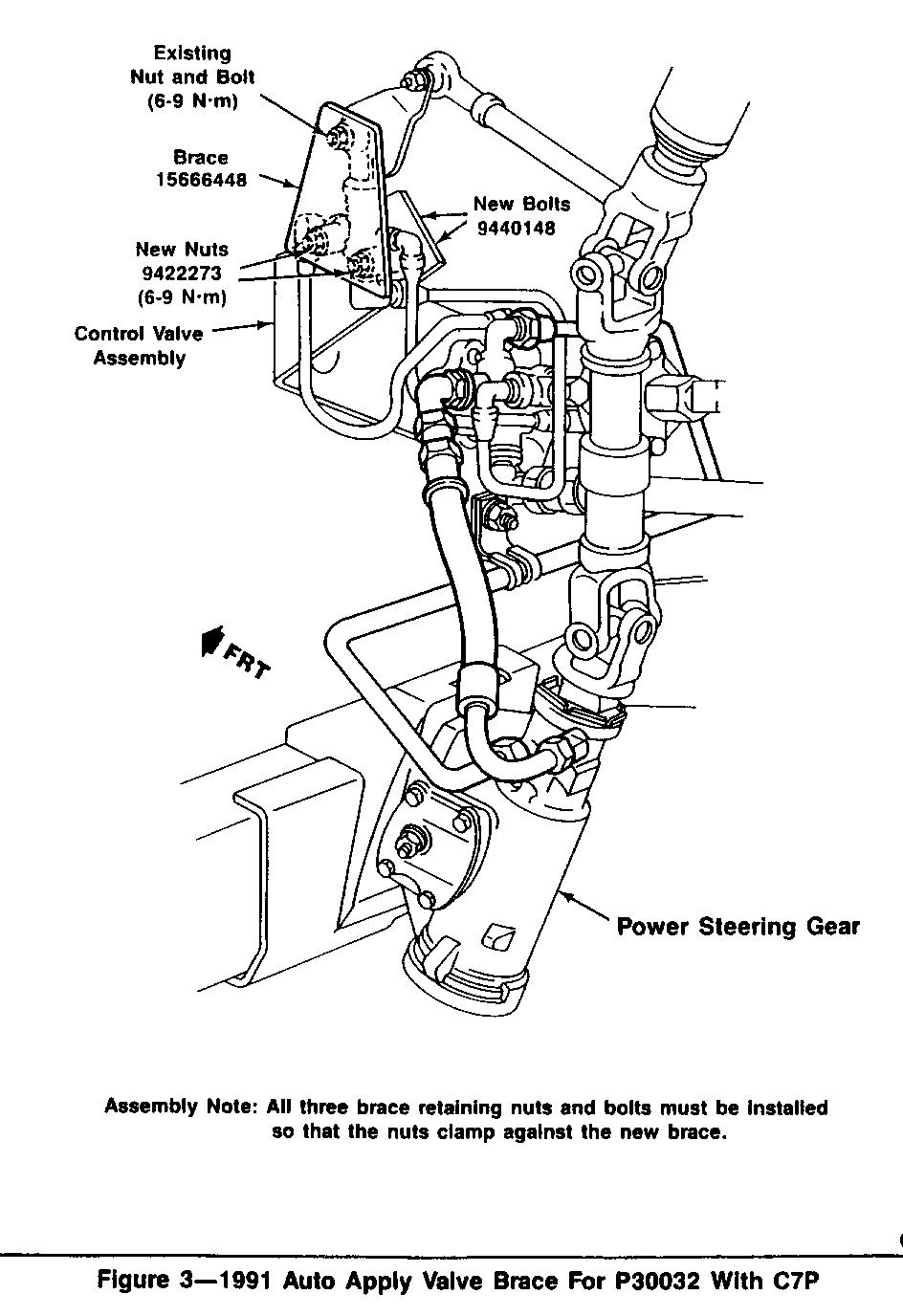
AUTO APPLY VALVE BRACE ON 1991 P3 16.000# MOTORHOMES WITH C7P --------------------------------------------------------------- The auto apply control valve may loosen at the cam actuator arm. This condition can be corrected by the installation of a brace, (P/N 15666448).
SERVICE PROCEDURE: Refer to Figure 3
1. Set parking brake, block wheels, ignition in the off position, and transmission in the park position.
2. Remove the left hand front splash shield, save all fasteners for reinstallation. Locate the park brake control valve on the left side above the steering gear, as shown in Figure 3.
3. Remove the three bolts shown in Figure 3. Discard the three washers, two 1/4" and one 5/16" washer. Replace the two 1/4" bolts and nuts with new hardware. Reuse the 3/16" bolt and nut.
4. Install the new brace (P/N 15666448) on the control valve so that the brace faces outboard. Install the two lower bolts and nuts. Reinstall the upper bolt and nut.
IMPORTANT: Nuts and bolts must be installed so that the nuts clamp against the new brace.
5. Torque the three nuts to 6 - 9 N.m. (4.5 to 6.6 ft.lbs.).
6. Reinstall the splash shield. Reuse the fasteners; torque to standard specifications (figure 3).
7. With the vehicle in the park position, remove the wheel blocks. Start the engine; release the manual park brake, and cycle the auto park apply system by moving the shift lever from park to drive. Observe that the vehicle's park brake functions properly.
8. Turn off vehicle; put on parking brake; shift lever in park. Inspect the control valve for any hydraulic leaks. Torque the fittings as required.
SERVICE PARTS INFORMATION
Part Description Quantity --------- ------------------ ------------------------------- 15666448 Brace Park Brake 1 (all P30032 at 16,000, Control Valve option C7P) 9440148 Bolt 1/4"-20 X 2.00" 2 (GM 280-M)
9422273 Nut 1/4"-20 2 (GM 280-M)


General Motors bulletins are intended for use by professional technicians, not a "do-it-yourselfer". They are written to inform those technicians of conditions that may occur on some vehicles, or to provide information that could assist in the proper service of a vehicle. Properly trained technicians have the equipment, tools, safety instructions and know-how to do a job properly and safely. If a condition is described, do not assume that the bulletin applies to your vehicle, or that your vehicle will have that condition. See a General Motors dealer servicing your brand of General Motors vehicle for information on whether your vehicle may benefit from the information.
