CAMPAIGN: DANA REAR AXLE BEARING RETAINER/END PLAY

Models: 1990 P3 Motorhome Chassis with Dana Model 80 Rear Axle
TO: ALL GENERAL MOTORS DEALERS
General Motors of Canada has determined that certain 1990 P3 Motorhome chassis equipped with a 4.63 ratio Dana model 80 rear axle, heavy duty chassis and 4-wheel disk brakes may have a missing rear axle outer bearing retaining ring and/or greater than specified bearing end play. Either of these conditions will allow the wheel rotor and hub assembly to shift relative to the spindle. This movement can cause the brake caliper piston to recede farther than normal into the piston bore which would require greater than normal brake fluid displacement when the service brakes are applied. If this movement were great enough, the failed system performance requirements of CMVSS 105, "Hydraulic Brake Systems," could not be met.
Correction will consist of inspecting both rear axle hubs for the condition(s) and correcting as necessary.
VEHICLES INVOLVED:
Involved are certain 1990 P3 Motorhome chassis equipped with a Dana model 80 rear axle and built within the following VIN breakpoints:
MODEL YEAR PLANT FROM THROUGH ---------- ------- ------- -------- 1990 GMC Detroit L3502333 L3503447 1990 CHEV Detroit L3316170 L3324370
All affected vehicles have been identified by the VIN listing provided to involved dealers with this bulletin. Any dealer not receiving a listing was not shipped any of the affected vehicles.
DEALER CAMPAIGN RESPONSIBILITY:
Dealers are to perform this campaign on all involved vehicles at no charge to owners, regardless of kilometres traveled, age of vehicle, or ownership, from this time forward.
Whenever a vehicle subject to this campaign is taken into your new or used vehicle inventory, or it is in your dealership for service, you are to ensure the campaign correction has been made before selling or releasing the vehicle.
Owners of vehicles recently sold from your new vehicle inventory are to be contacted by the dealer, and arrangements made to make the required modification according to instructions contained in this bulletin.
CAMPAIGN PROCEDURE:
Refer to Section 4 of the Service Policies and Procedures Manual for the detailed procedure on handling Product Campaigns. Dealers are requested to complete the campaign on all transfers as soon as possible.
OWNER NOTIFICATION:
All owners of record at the time of campaign release are shown on the attached computer listing and have been notified by first class mail from General Motors. The listings provided are for campaign activity only and should not be used for any other purpose.
PARTS INFORMATION:
Parts required to complete this campaign should be ordered through regular channels, as follows:
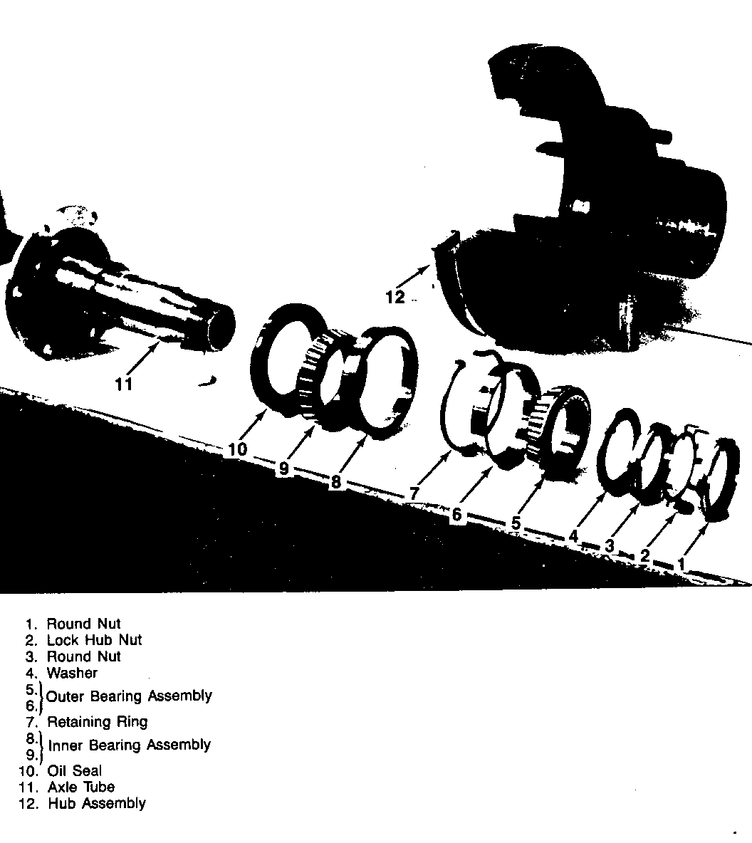
Part Number Description Quantity/Vehicle ------------ -------------------- ---------------- 473636 Round Nut (1 & 3) 4 473629 Lock Hub Nut (2) 2 473628 Washer (4) 2 9412405 Outer Bearing Asm. (5 & 6) 2 594324 Retaining Ring (7) 2 9412426 Inner Bearing Asm. (8 & 9) 2 15589475 Wheel Seal (10) 2
PARTS AND LABOUR CLAIM INFORMATION:
Credit for the campaign work performed will be paid upon receipt of a properly completed campaign claim card, RAPID terminal or DCS transmission in accordance with the following:
Repair Code Description Time Allowance ----------- ------------------------ -------------- 2A Inspect Hub Assembly - 2.1 Replace Bearings As Required
Time allowance includes 0. 1 hour for dealer administrative detail associated with this campaign. Parts credit will be based on dealer net plus 30% to cover parts handling.
SERVICE PROCEDURE:
A. BEARING END PLAY INSPECTION PROCEDURE
Tools Required: J8001 Dial Indicator Set J23409 Dial Indicator Extension Set J26900-13 Magnetic Base
1. Check the wheel bearing play by grasping the tire at the top and pulling and pushing back and forth, or by using a pry bar under the tire. If the tapered roller bearings are properly adjusted, movement of the brake disc in relation to the brake flange plate will be barely noticeable and the wheel will turn freely. If the movement is excessive then bearings are out of adjustment and possibly damaged. Using a dial indicator (J8001) magnetic base (J26900-13) and extension arm set (J23409) verify any apparently excessive bearing end play by setting dial indicator on axle tube and set roller end to rotor of hub. If when pulling the hub outward, movement is within .001 to .010 inch end play is acceptable. End play in excess of .010 inch is unacceptable and should be repaired.
NOTE: MAKE SURE THE BRAKES ARE FULLY RELEASED AND DO NOT DRAG WHEN CHECKING FOR WHEEL BEARING PLAY.
2. If excessive bearing end play is detected then include replacement of inner and outer bearings (5 and 9) and oil seal (10) as illustrated in Figure 1, according to procedure C "Retaining Ring is Not Missing" or Procedure D "Retaining Ring is Missing" whichever is found necessary. Also check the axle shaft for any damages that may have occurred from axle shaft contact with inner side of the axle tube (11). Replace as necessary.
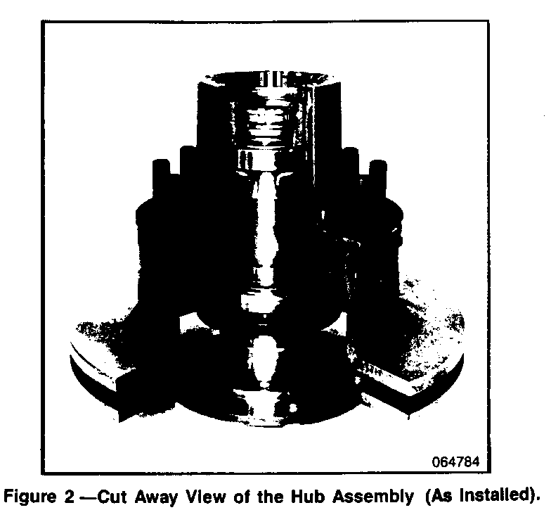
B. RETAINING RING INSPECTION PROCEDURE (Ref. Figures 1 and 2)
Tool Required: J2222-C Wheel Bearing Nut Wrench
NOTICE: When fasteners are removed, always reinstall them at the same location from which they were removed. If a fastener needs to be replaced, use the correct part number for that application. If the correct part number fastener is not available, a fastener of equal size and strength (or stronger) may be used. Fasteners that are not reused and those requiring thread locking compound will be called out. The correct torque value must be used when installing fasteners that require it. If the above conditions are not followed parts or systems damage could result.
1. Raise the vehicle until the wheel is free to rotate. Remove the wheel and tire assembly.
2. Disconnect and suspend the caliper. Refer to Section 5A2 of the 1990 Service Manual. Inspect brake linings and caliper rotor for possible cracks or damage.
NOTE: DO NOT ALLOW THE BRAKE COMPONENTS TO HANG FROM THE FLEXIBLE HOSES AS DAMAGE TO THE HOSES MAY OCCUR.
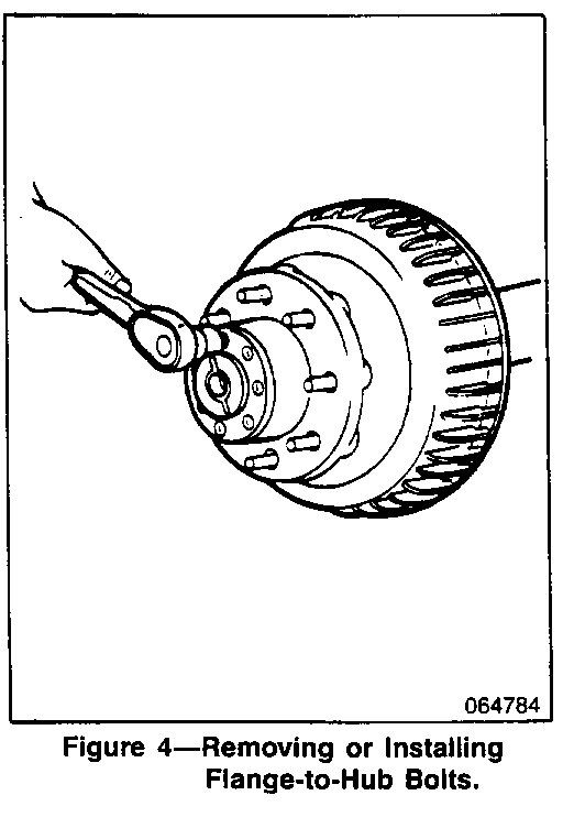
3. Remove axle shaft cap-to-hub bolts (Figure 4). Rap the axle shaft flange lightly with a soft faced hammer to loosen the shaft (not pictured) and grip the rib on the axle shaft flange with a locking plier and twist to start shaft removal. Remove the axle shaft from the tube (11) and remove the old RTV or gasket. Clean the axle shaft flange and the outside face of the hub (12).
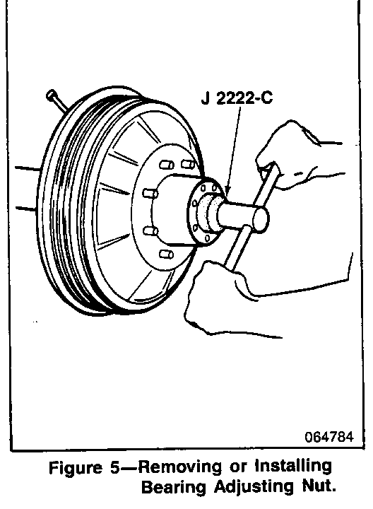
4. Remove the outer locknut (1) using J2222-C, the lock washer (2), the adjusting nut (3) and the washer (4) from the axle tube (Figure 5). Inspect and replace as necessary.
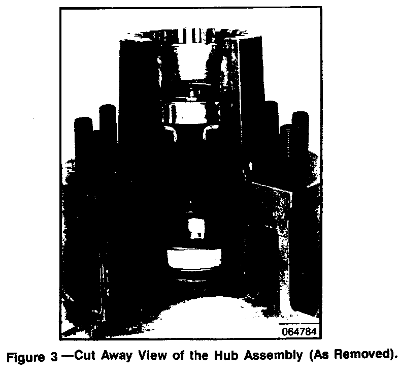
5. Remove the hub (12) and lay it on a flat surface with a shop towel underneath to catch the bearing and oil seal if disassembly is required also, to keep it away from collecting dirt. Check inside the hub for missing retaining ring (7) by looking from the inner bearing (8 and 9) toward the outer one (5 and 6) inside the hub (Figure 3) retaining ring (7) should be seated in groove against the inner surface of outer bearing (5 and 6).
C. RETAINING RING IS NOT MISSING
1. Reinstall the hub (Figure 3) to the axle tube (1 1). Make sure the bearings and the oil seal (10) are positioned properly. Apply a light coat of high melting point EP bearing lubricant to the contact surfaces and the outside of the axle tube (I 1). Refer to "Maintenance and Lubrication" in Section OB of the 1990 Service Manual.
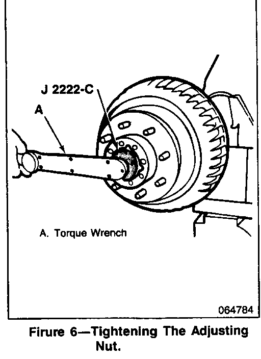
2. Reinstall the washer (4) and the adjusting nut (3). Tighten the adjusting nut to 68 N.m (50 lbs ft.) using J2222-C while rotating the hub assembly, making certain the bearing cones are seated and in contact with the spindle shoulder (Figure 6). To adjust the adjusting nut (3), back it off and retighten to 41-54 N.m (30-40 lbs.ft.) while hub is rotated. Back off the adjusting nut (3) 135 to 150 degrees.
3. Reinstall the lock washer (2) and bend one tang of the lock washer over a flat of the adjusting nut (3), 30 degrees minimum.
4. Reinstall the outer lock nut (1) and tighten to 88 N.m (65 lbs. ft.) minimum. Bend one tang of the lock washer (2) over a flat of the outer nut (1), 60 degrees minimum.
5. Reinstall the axle shaft (not pictured) with gasket (if used) or RTV applied. Be sure the shaft splines mesh into the differential side gear and align the axle shaft cap holes with the hub holes. Retighten bolts to 156 N.m (I 15 lbs. ft.) and reconnect caliper/linings as specified in Section 5A2 of the 1990 Service Manual.
6. Reinstall wheel and tire assembly and lower the vehicle.
D. RETAINING RING IS MISSING
When the visual inspection of the hub (Figure 3) indicates missing retaining ring (7) then, the bearings and oil seal (10) must be disconnected and replaced in addition to the new retaining ring installation.
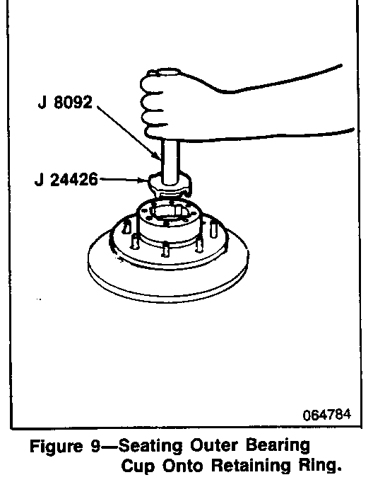
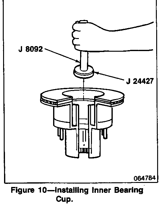
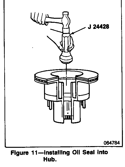
Tools Required: J8092 Driver Handle J8608 Outer Pinion Bearing Cup Installer J24426 Outer Wheel Bearing Cup Installer J24427 Inner Wheel Bearing Cup Installer J24428 Axle Shaft Seal Installer
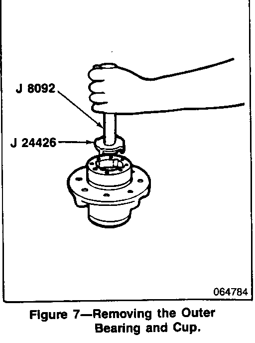
1. After laying the hub (Figure 3) on a flat surface with a shop towel to catch the bearing and oil seal, use a drift and remove the inner bearing (9) and the oil seal (10). Also, remove the outer bearing (5) using J8092 with J24426 to drive the bearing (5) and cup (6) from the hub (Figure 7).
2. Clean lubricant from the axle tube (11) and inside the hub (12) and inspect cups (6 and 8) for pits and cracks. Replace as necessary.
3. Pack the new inner and outer bearings (5 and 9) with wheel bearing lubricant 1051344 or equivalent. Refer to "Maintenance and Lubrication" in Section OB of the 1990 Service Manual.
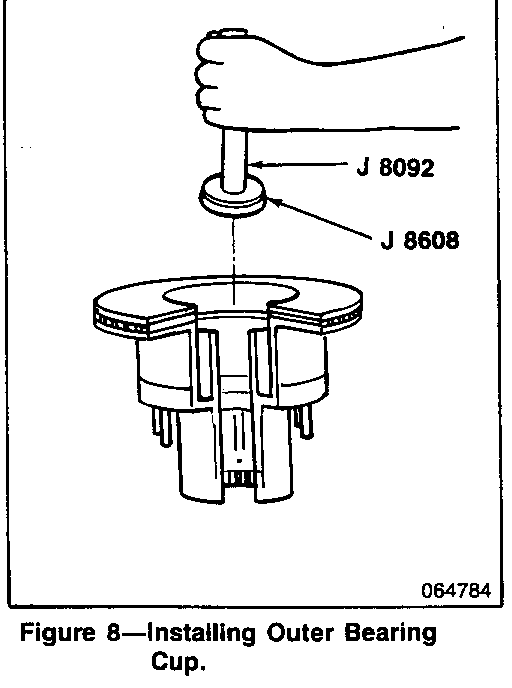
4. Install the outer bearing cup (6) into the hub (12). Drive the cup (6) into the hub (12) using J8092 and J8608 beyond the retaining ring groove (Figure 8).
NOTE: Be sure J8608 is installed upside down on J8092 so that the chamfer does not contact the bearing cup (6).
5. Install the retaining ring (7) into the groove and drive the outer bearing cup (6) back onto the retaining ring (7) using J24426 (Figure 9).
6. Install the inner bearing cup (8) using J8092 and J24427 (Figure 10). Drive the cup (8) into place until it is seated against the hub shoulder.
7. Install the inner wheel bearing (9), oil seal (10) using J24428 (Figure 11), and the outer wheel bearing (5).
8. Install the hub (12) to the axle tube (11) and adjust the bearing preload as specified in Section "Retaining Ring Is Not Missing" above.
9. Install "Campaign Identification Label."
INSTALLATION OF CAMPAIGN IDENTIFICATION LABEL
Clean surface of radiator upper mounting panel and apply a Campaign Identification Label. Make sure the correct campaign number is inserted on the label. This will indicate that the campaign has been completed.
INSERT CAMPAIGN NUMBER
INSERT DEALER CODE
Dear General Motors Customer:
General Motors of Canada has determined that certain 1990 P3 Motorhome chassis equipped with a 4.63 ratio Dana model 80 rear axle, heavy duty chassis and 4-wheel disk brakes may have a missing rear axle outer bearing retaining ling and/or greater than specified bearing end play. Either of these conditions will allow the wheel rotor and hub assembly to shift relative to the spindle. This movement can cause the brake caliper piston to recede farther than normal into the piston bore which would require greater than normal brake fluid displacement when the service brakes are applied. If this movement were great enough, the failed system performance requirements of CMVSS 105, "Hydraulic Brake Systems," could not be met.
Correction will consist of inspecting both rear axle hubs for the condition(s) and correcting as necessary.
This service will be completed for you at no charge.
Please contact your GM dealer as soon as possible to arrange a service date.
This letter identifies your vehicle. Presentation of this letter to your dealer will assist their Service personnel in completing the necessary correction to your vehicle in the shortest possible time.
Further assistance, if required, may be obtained from our Customer Assistance Centre, toll free, by calling 1-800-263-3777, or if you live in Quebec, 1-800-263-7854.
We are sorry to cause you this inconvenience; however, we have taken this action in the interest of your continued satisfaction with our products.
General Motors bulletins are intended for use by professional technicians, not a "do-it-yourselfer". They are written to inform those technicians of conditions that may occur on some vehicles, or to provide information that could assist in the proper service of a vehicle. Properly trained technicians have the equipment, tools, safety instructions and know-how to do a job properly and safely. If a condition is described, do not assume that the bulletin applies to your vehicle, or that your vehicle will have that condition. See a General Motors dealer servicing your brand of General Motors vehicle for information on whether your vehicle may benefit from the information.
