DELCO FREEDOM BATTERY DIAGNOSIS-CHARGING INFORMATION

VEHICLES AFFECTED: ALL MODELS
The following information will explain the characteristics of the Delco Freedom battery and the effects of parasitic loads (small constant drains on the battery due to standard and optional equipment). The effect of outside temperatures on battery power and proper battery charging and testing procedures are also discussed.
Read all this information; try recharging a deeply discharged battery, review training materials if necessary, and become convinced that Delco batteries are GOOD batteries. Most deeply discharged batteries CAN be recharged if proper procedures are followed.
Examples of conditions causing low charged of discharged batteries are:
- extended storage of vehicles - batteries being less than adequately charged when received - extended cranking periods due to plug fouling - driver habits - incorrect interpretation of the charge indicator - inability to determine the correct ampere-hour charging rate for a discharged battery - burned out charge/gen light bulb causing "No Charge" condition - charging system problems increased - continuous current draw on the battery through parasitic drain
PARASITIC LOADS
Some vehicles may have several electrical devices which result in continuous current drains on their batteries. Batteries on vehicles not being used for an extended period may become discharged by these small current drains called parasitic loads.
Any battery discharged by parasitic loading and then allowed to stand in this condition for a period of time may not readily accept recharge. However, if properly recharged, batteries will return to a good usable condition.
Extremely discharged batteries can freeze at temperatures as high as -6.5 DEG C (+20 DEG F), and freezing can also cause permanent damage. Permanent damage to discharged batteries can also be accelerated by high temperatures.
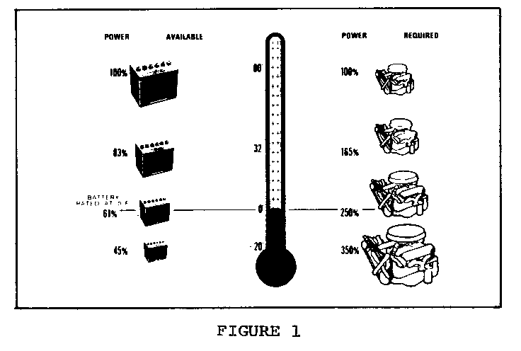
Figure 1 shows what happens to available battery power and the power required to start the engine at different outside temperatures.
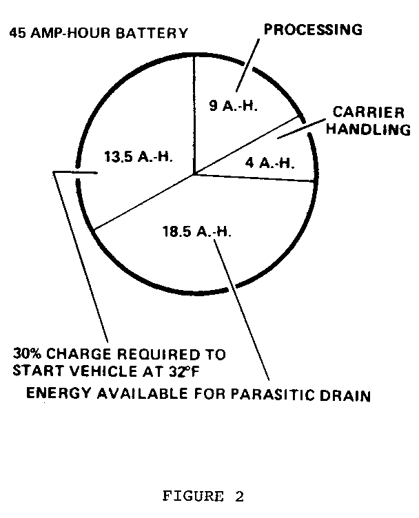
Figure 2 shows a typical amount of current used in getting a vehicle built and delivered to the dealer, how much is available for electrical devices, and how much is necessary to start the vehicle. The battery begins to be discharged at the time it is connected. Current is used during plant build, carrier handling, dealer storage, and new car preparation. During this entire period, the vehicle is never driven long enough nor at a high enough RPM to bring the battery back up to a full state of charge.
A vehicle sitting for 2 months at 0 DEG C (32 DEG F) most likely will not start due to parasitic load and self-discharge.
Examples of parasitic loads:
DEVICE MILLIAMP DRAW
Voltage Regulator .001 Digital Clock .003-.0045 Quartz Clock .007 ECM .0065-.008 ETR Radio and Clock 7 Load Leveling 4 Memory Seat 3 Twilight Sentinel 3
TYPICAL PARASITIC LOADS LOAD (MILLIAMPS) AT MODEL 12.6 BATTERY VOLTS
N 16 J 10 A 9 H 9 G 9 C 13 E 50 B 11
Chemical reactions take place in all batteries, even if they are not connected to a load. Therefore, a certain amount of self-discharge is always occurring. The higher the ambient temperature, the greater the amount of self-discharge. This explains why the number of discharged batteries increases in very hot weather. The Delco Freedom battery has a much lower rate of self-discharge than conventional batteries. The chart below demonstrates how the increased temperature affects self-discharge.
RATE OF TEMPERATURE SELF-DISCHARGE (AMPS) DEG F DEG C
120 49 .0112 100 38 .0068 70 21 .0018 50 10 .0008
To prevent battery damage and difficulty in recharging, any vehicles that are not going to be in service within a 30-60 day period should have ground cable(s) disconnected to remove the constant drain on the batteries. If this is not possible, batteries should be recharged periodically every 30-60 days until the green dot is visible. The longer a vehicle sits on a dealer's lot with the battery cables connected, the higher the probability that it will have to be recharged due to the drain caused by parasitic loads and self-discharged.
CHARGING TIME REQUIRED
The time required to charge a battery will vary dependant upon the following factors:
Ampere Size of Battery - A completely discharged large heavy-duty battery requires more than twice the recharging as a completely discharged small passenger car battery.
Temperature - A longer time will be needed to charge any battery at -18 DEG C (0 DEG F) than 27 DEG C (80 DEG F). When a fast charger is connected to a cold battery, the current accepted by the battery will be very low at first, then in time the battery will accept a higher rate as the battery warms.
Charger Capacity - A charger which can supply only five amperes will require a much longer period of charging than a charger that can supply 30 amperes or more.
State-Of-Charge - A completely discharged battery requires more than twice as much charge as a one-half charged battery. Because the electrolyte is nearly pure water and a poor conductor in a completely discharged battery, the current accepted by the batter is very low at first. Later, as the charging current causes the electrolyte acid content to increase, the charging current will likewise increase.
CHARGING A VERY LOW OR COMPLETELY DISCHARGED BATTERY
The following procedure should be used to recharge a very low or completely discharged battery:
Unless the procedure is properly followed, a perfectly good battery may be needlessly replaced.
1. Measure voltage at battery terminals with a digital voltmeter. If below 10 volts, then the charge current will be very low and It could take some time before it accepts a current in excess of a few milliamperes. Such low current may not be detectable on ammeters used on charges.
2. Set battery charger on high setting.
3. Some chargers feature polarity protection circuitry which prevents charging unless the charger leads are connected to the battery terminals correctly. A completely discharged battery may not have enough voltage to activate this circuitry, even though leads are connected properly, making it appear that the battery will not accept charging current. Therefore follow the specific charger manufacturer's instructign telling how to bypass or override the circuitry so that the charger will turn on and charge a low-voltage battery.
4. Battery charges vary in the amount of voltage and current they provide. The time required for the battery to accept measurable charger current at various voltages may be as follows:
Charger Voltage Hours
A. 16.0 or more Up to 4 hrs. B. 14.0 - 15.9 Up to 8 hrs. C. 13.9 or less Up to 16 hrs.
If the amp meter on the battery charger indicates that the battery is still not accepting a charge at the end of the above charging times, the battery should be replaced.
If the charge current is measurable during the charging time, the battery is considered to be good and charging should be completed in the normal manner.
5. It is important to remember that a completely discharged battery must be recharged for a sufficient number of ampere hours (AH) to restore it to a usable state. As a general rule of thumb, using the reserve capacity rating (RC) (refer to Section 6D of the appropriate Service Manual) of the battery as the number of ampere hours of charge will usually bring the green dot into view.
For example, if battery is rated at 75 RC minutes, it would be completely recharged as follows:
10 ampere charge x 7-1/2 hrs = 75 AH or 25 ampere charge x 3 hrs = 75 AH, etc.
6. It is recommended that any battery recharged by this procedure be LOAD TESTED to establish serviceability.
A battery has two ratings: (1) a reserve capacity rating at 27 degrees celcius (80 degrees farenheit) which is the time a fully charged battery will operate the car with no generator operation; and (2) a cold rating at -18 degrees celcius (0 degrees farenheit) which indicates the cranking load capacity (see battery label or Specifications chart at the end of the Battery section for specific battery ratings).
RESERVE CAPACITY
The "Reserve Capacity" is the maximum length of time it is possible to travel at night with minimum electrical load and no generator output.
Expressed in minutes it is the time required for a fully charged battery, at a temperature of 27 DEG C (80 DEG F) being discharged at a constant current of 25-amperes, to reach a terminal vol-tage of 10.5 volts.
COLD CRANKING AMPERAGE
The "Cold Cranking Amperage" test is expressed at a battery temperature of -18 DEG C (0 DEG F). The current rating is the minimum amperage, which must be maintained by the battery for 30 seconds at the specified temperature, while meeting a minimum voltage requirement of 7.2 volts. This rating is a measure of cold cranking capacity.
The battery is not designed to last indefinitely; however, with proper care, it will provide many years of service.
If the battery tests good, but fails to perform satisfactorily in service for no apparent reason, the following are some of the more important factors that may point to the cause of trouble:
1. Vehicles accessories left on overnight. 2. Slow average driving speeds for short periods.
3. The vehicle's electrical load is more than the generator output, particularly with the particularly with the addition of aftermarket equipment.
4. Defects in the charging system such as electrical shorts, slipping fan belt, faulty generator, or faulty voltage regulator.
5. Battery abuse, including failure to keep the battery cable terminals clean and tight, or loose battery hold-down. See "Service procedures" for torque specifications.
6. Mechanical problems in the electrical system, such as shorted or pinched wires.
BATTERY CONNECTIONS
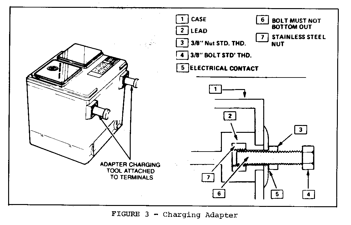
Load testing requires the use of battery side terminal adapters the same as with charging to ensure good connections (see Figure 3).
BATTERY TESTING
Before testing a battery, it is important that the battery has a proper charge.
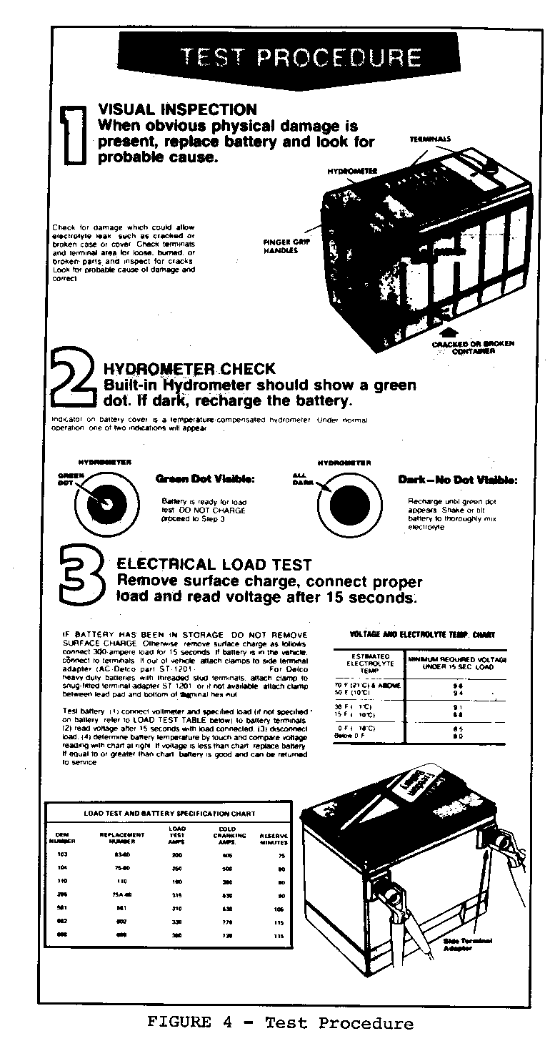
1. Connect a digital voltmeter and a battery load tester across battery terminals.
2. Apply 300 ampere load for 15 seconds to remove surface charge from battery. Remove load.
3. Wait 15 seconds to let battery recover and apply specified load as indicated on battery label. Read voltage after 15 seconds with specified load applied, then remove load.
4. Temperature of the battery will change the minimum voltage to pass the load test. To properly determine minimum voltage, estimate temperature battery has been exposed to for the last several hours, i.e. , room temperature or outside ambient to within 5.6 DEG C (10 DEG F). If voltage is equal to or above minimum voltage listed in the appropriate Service Manual, Section 6D, the battery is good and should be returned to service. If voltage is less than minimum requirement, replace battery.
CAUTION
All batteries generate hydrogen gas which is highly flammable. If ignited by a spark or flame, the gas may explode violently, causing spraying of acid, fragmentation of the battery, and possible severe personal injuries. wear approved eye protection. Battery fluid is a corrosive acid. Flush any contacted area with water immediately and thoroughly.
VISUAL INSPECTION
Check for obvious damage, such ajs cracked or broken case or covert that is permitting loss of electrolyte. If obvious damage is noted, replace the battery. Determine the cause of, damage and correct as needed. If battery terminals are severely damaged, such as loose, burned, or. broken, replacement of the battery is recommended. Evidence of small amounts of electrolyte leakage, especially arouffd the vent holes, does not necessarily indicate the battery is bad - the leakage could have been caused by overcharging or by excessive tipping of the battery.
CARRIER AND HOLD-DOWN
The battery carrier and hold-down clamp should be clean and free from corrosion before installing battery.
The carrier should be in a sound condition so that it will hold the battery securely and keep it level. Make certain there are no parts in the carrier before installing battery.
To prevent the battery from shaking in its carrier, the hold-down bolts should be tight, but not overtightened.
READING BUILT-IN HYDROMETER
Look down into the built-in hydrometer (clean and use a flashlight if necessary) to observe its reading (refer to Figure 4).
Green Dot Visible - Any green appearance is interpreted as a "green dot" and indicates that the battery is 65% or above in state of charge and is ready for use or testing. A fully charged battery should read 12.6 or more volts.
Dark, Green Dot Not Visible - Indicates the battery is below 65% state of charge and needs charging prior to testing.
Clear of Light Yellow - This means the fluid level is below the bottom of the hydrometer. This may have been caused by excessive or prolonged charging, a cracked or broken case, excessive tipping, or normal battery wearout. Replace battery. Do not charge, test or jump-start. A dark reading may be misinterpreted as a clear or light filtering through the new translucent case. Shake the battery to determine the fluid level and shield the battery sides from light to determine the true reading before replacing the battery.
BATTERY CHARGING
When charging a sealed battery, tkie following safety precautions must be followed:
Do not charge battery if hydrometer is clear or light yellow. Replace battery.
If the battery feels hot, 125 degrees farenheit (50 degrees celcius), or violent gassing or spewing of electrolyte through the vent hole occurs, discontinue charging or reduce charging rate.
CHARGING PROCEDURE
Bolts alone, screwed into the side terminal, should not be used for the connection of battery charger cables since the. mating threads inside the battery terminals provide a very small contact surface, which has high resistance to current flow.
The high resistance can prevent adequate charging current from reaching the battery, creating the appearance of the battery not accepting a charge, or at the least requiring longer charging time. It also explains why some batteries are called bad when they are load tested, but are obviously good batteries when checked with proper connections at the terminals.
There are two ways of connecting to the side terminals to charge a battery:
- By use of an adapter charging tool (see Figure 3). The number of this tool is AC-Delco ST-1201 or Borroughs BT-3572-2. The adapter should be snugged up against the lead pads of the battery with pliers to keep resistance between the adapter and battery terminals at a minimum. This is the preferred method.
- By the use of a 3/8" bolt with standard threads (16 UNC) and 3/8" nuts with standard threads (see Figure 3).
a. Screw 3/8" nut onto 3/8" bolt (1-1/2" or longer).
b. Using fingers, screw one bolt into each side terminal until it bottoms out, and then back off one full term. (Do not tighten with wrench as bolts can be driven through case).
c. Holding the bolt, screw the nut down on the bolt until the nut is against the battery terminal lead pad. Snug nut with pliers. (Do not overtighten as nut inside battery terminal could be pulled out).
d. Attach the charger or tester leads to the 3/8" nuts and follow normal charging and testing procedures. The main charging or load test current will be carried through the lead pads of the battery terminals and not through the nuts inside the terminals.
1. Batteries with green dot showing do not require charging unless they have just been discharged (such as in cranking vehicle).
2. When charging side-terminal batteries, install adapter kit AC Delco part number ST-1201 or Borroughs BT-3572-2. Refer to Figure 3.
3. Make sure all charger connections are clean and tight.
4. For best results, batteries should be charged while they are at room temperature. A battery that is extremely cold may not accept current for several hours after starting charger.
5. Charge battery until green dot appears (see Charging Time Required). Battery should be checked every half-hour while charging. Tipping or shaking battery may be necessary to make green dot appear.
6. After charging, battery should be tested as outlined in "BATTERY TESTING".
EQUIPMENT
A battery charger that is classified as a "Fast Charge" unit generally is considered sufficient as they are usually capable of about an 18 volt input. When investigating a charger, the following items should be considered essential:
1. A 40-50 amp minimum charge rate.
2. To prevent overcharging, the unit should have a timer (1 or 2 hours) or a voltage regulator that would regulate a maximum of 18 volts.
3. Ampmeter or charging rate meter.
4. An automatic polarity protector.
Some equipment that is available includes the Associated No. 6001 and the Sun 720. Very few chargers have sensitive low- voltage meters, therefore, separate voltmeters may be necessary.
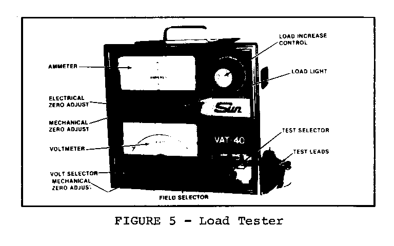
A suitable load tester such as the Sun VAT-40 shown in Figure 5 (or equivalent) is available and is a very useful tool to properly diagnose battery problems.
General Motors bulletins are intended for use by professional technicians, not a "do-it-yourselfer". They are written to inform those technicians of conditions that may occur on some vehicles, or to provide information that could assist in the proper service of a vehicle. Properly trained technicians have the equipment, tools, safety instructions and know-how to do a job properly and safely. If a condition is described, do not assume that the bulletin applies to your vehicle, or that your vehicle will have that condition. See a General Motors dealer servicing your brand of General Motors vehicle for information on whether your vehicle may benefit from the information.
