Notice:
• Remove the attaching bolts securing the fuel rail
assembly to the lower intake manifold in order to prevent damage to the fuel
rail assembly. • Carefully remove the fuel rail assembly in order to prevent damage
to the injector electrical connector terminals and the injector spray tips. • Cap the fittings and plug the holes plugged when servicing the
fuel rail in order to prevent dirt and other contaminants from entering open
lines and passages. Clean the fuel rail assembly with a GM X-30A spray
type engine cleaner or the equivalent before removal. Do Not submerge the
fuel rail in a cleaning solvent
An eight digit identification number is located on the fuel rail assembly. Refer to this number if servicing or part replacement is required. Before removal, the fuel rail assembly may be cleaned with a spray type engine cleaner, GM X-30A or equivalent, following package instructions. Do Not soak fuel rails in liquid cleaning solvent.
Removal Procedure
- Disconnect the negative battery cable.
- Relieve the fuel system pressure. Refer to the Fuel Pressure Relief Procedure .
- Remove the intake manifold plenum. Refer to Engine Mechanical.
- Remove the high voltage switch assembly.
- Disconnect the engine fuel pipes at the rail.
- Remove the engine fuel pipe bracket bolt.
- Remove the fuel inlet and return line O-rings and discard.
- Disconnect the injector electrical connectors and remove from the coil bracket.
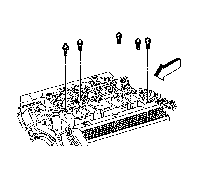
- Remove the fuel rail retaining bolts (5).
- Disconnect the vacuum hose line to pressure regulator.
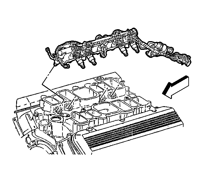
- Remove the fuel rail from the intake manifold.
- Remove the injector O-ring seal from the spray tip end of each injector. Discard the seals. With the O-ring removed, the O-ring backup may slip off of the injector. Be sure to retain O-ring backup for reuse.
Caution: Unless directed otherwise, the ignition and start switch must be in the OFF or LOCK position, and all electrical loads must be OFF before servicing any electrical component. Disconnect the negative battery cable to prevent an electrical spark should a tool or equipment come in contact with an exposed electrical terminal. Failure to follow these precautions may result in personal injury and/or damage to the vehicle or its components.
Installation Procedure
Important: Ensure that the O-ring backups are on the injectors before installing the new O-rings. Lubricate the new injector O-ring seals with clean engine oil and install on the spray tip end of each injector.
- Install the fuel rail assembly in intake manifold. Tilt the rail assembly to install the injectors.
- Install the fuel rail attaching bolts.
- Connect the injector electrical connectors.
- Install the new O-rings on the fuel pipes.
- Connect the fuel feed and return lines.
- Connect the negative battery cable.
- Install the fuel filler cap.
- Check for fuel leaks.
- Install the intake manifold plenum. Refer to Engine Mechanical.
Notice: Use the correct fastener in the correct location. Replacement fasteners must be the correct part number for that application. Fasteners requiring replacement or fasteners requiring the use of thread locking compound or sealant are identified in the service procedure. Do not use paints, lubricants, or corrosion inhibitors on fasteners or fastener joint surfaces unless specified. These coatings affect fastener torque and joint clamping force and may damage the fastener. Use the correct tightening sequence and specifications when installing fasteners in order to avoid damage to parts and systems.
Tighten
Tighten the fuel rail attaching bolts to 10 N·m (89 lb in).
Notice: Use the correct fastener in the correct location. Replacement fasteners must be the correct part number for that application. Fasteners requiring replacement or fasteners requiring the use of thread locking compound or sealant are identified in the service procedure. Do not use paints, lubricants, or corrosion inhibitors on fasteners or fastener joint surfaces unless specified. These coatings affect fastener torque and joint clamping force and may damage the fastener. Use the correct tightening sequence and specifications when installing fasteners in order to avoid damage to parts and systems.
Tighten
| • | Engine fuel pipe nuts to 27 N·m (20 lb ft). |
| • | Use a back-up wrench on the fittings to prevent them from turning. |
| 8.1. | Turn the ignition switch to the ON position for 2 seconds. |
| 8.2. | Turn the ignition switch to the OFF position for 10 seconds. |
| 8.3. | Again, turn the ignition switch to the ON position. |
| 8.4. | Check for fuel leaks. |
