Fuel Hose/Pipes Assembly Replacement Fuel/Vapor Pipes 4DR Utility
Removal Procedure
Notice:
| • | Do not attempt to straighten kinked nylon pipes. Replace any kinked
nylon pipes in order to prevent damage to the vehicle. |
| • | Do not attempt to repair sections of nylon pipes. Replace damaged
nylon pipes. |
| • | Replace the vapor pipes with original equipment or parts that
meet GM specifications. |
| • | Replace the vapor hoses with original equipment or parts meeting
GM specifications. Use only reinforced fuel-resistant hose identified with
the word Fluoroelastomer or GM 6163M on the hose. |
Caution: Unless directed otherwise, the ignition and start switch must be in the OFF or LOCK position, and all electrical loads must be OFF before servicing
any electrical component. Disconnect the negative battery cable to prevent an electrical spark should a tool or equipment come in contact with an exposed electrical terminal. Failure to follow these precautions may result in personal injury and/or damage to
the vehicle or its components.
- Disconnect
the negative battery cable.
- Relieve the fuel system pressure. Refer to Fuel Pressure Relief Procedure
.
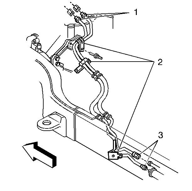
- Disconnect the fittings
(1) at the engine compartment fuel feed and return pipes.
- Disconnect the fuel pipe attaching hardware (2).
- Disconnect the fuel feed and return pipe nuts at the fuel filter
(3) and the return pipe union.
- Remove the fuel tank.
| • | Refer to Fuel Tank Replacement (Pick-up - Side Tank)
for the Pick-up. |
| • | Refer to Fuel Tank Replacement (Extended Cab - Side Tank)
for the Extended Cab. |
| • | Refer to Fuel Tank Replacement (Cab and Chassis - Side Tank)
for the Cab and Chassis with a side tank. |
| • | Refer to Fuel Tank Replacement (4 Door Utility)
for the 4DR Utility. |
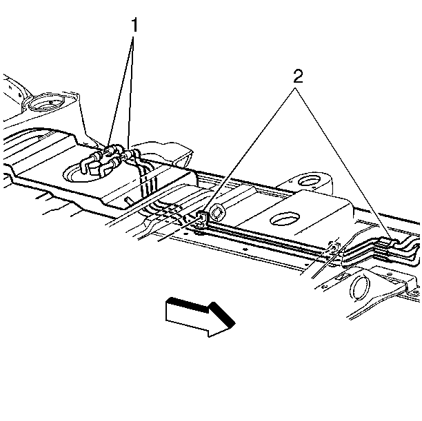
- Disconnect the fuel feed
and vapor hoses (1). On 4DR Utility, the quick-connect fittings at the fuel
sender assembly. Refer to Quick Connect Fitting(s) Service (Metal Collar)
or Quick Connect Fitting(s) Service (Plastic Collar)
.
- Remove the hardware retaining section of pipe to be replaced (2).
Note location of attaching hardware for installation.
- Remove the section of pipe and hoses.
- Remove rust or burrs from the engine compartment fuel pipes by
the following procedure:
| 10.1. | Use emery cloth in a radial motion with the fuel pipe end in order
to prevent damage to the O-ring sealing surface. |
| 10.2. | Using a clean shop towel, wipe off the male tube ends. |
| 10.3. | Inspect all the connectors for dirt and burrs. Clean or replace
the components/assemblies as required. |
Installation Procedure
Notice: Use the correct fastener in the correct location. Replacement fasteners
must be the correct part number for that application. Fasteners requiring
replacement or fasteners requiring the use of thread locking compound or sealant
are identified in the service procedure. Do not use paints, lubricants, or
corrosion inhibitors on fasteners or fastener joint surfaces unless specified.
These coatings affect fastener torque and joint clamping force and may damage
the fastener. Use the correct tightening sequence and specifications when
installing fasteners in order to avoid damage to parts and systems.
- Connect the fuel
feed and return pipes to the engine fuel pipes (1).
Tighten
Fuel pipe attaching nuts to 27 N·m (20 lb ft)
using a back-up wrench.
- Position new fuel pipe harness in original location and fuel pipe
harness attaching hardware (2).
- Connect the fuel feed pipe to the fuel filter and the return pipe
to the union (3).
- Connect the quick-connect
fittings for the fuel and vapor pipes at the fuel sender assembly (1). Refer
to Quick Connect Fitting(s) Service (Metal Collar)
or Quick Connect Fitting(s) Service (Plastic Collar)
.
- Install the fuel tank and attaching hardware (2) if the tank was
removed.
- Tighten the fuel filler cap.
- Connect the negative battery cable.
- Check for fuel leaks.
| 8.1. | Turn the ignition switch to the ON position for 2 seconds. |
| 8.2. | Turn the ignition switch to the OFF position for 10 seconds. |
| 8.3. | Again, turn the ignition switch to the ON position. |
| 8.4. | Check for fuel leaks. |
Fuel Hose/Pipes Assembly Replacement Fuel/Vapor Pipes Exc. 4DR Util
Removal Procedure
Caution: Unless directed otherwise, the ignition and start switch must be in the OFF or LOCK position, and all electrical loads must be OFF before servicing
any electrical component. Disconnect the negative battery cable to prevent an electrical spark should a tool or equipment come in contact with an exposed electrical terminal. Failure to follow these precautions may result in personal injury and/or damage to
the vehicle or its components.
- Disconnect
the negative battery cable.
- Relieve the fuel system pressure. Refer to Fuel Pressure Relief Procedure
.
- Disconnect the fittings
(1) at the engine compartment fuel feed and return pipes.
- Disconnect the fuel pipe attaching hardware (2).
- Disconnect the fuel feed and return pipe nuts at the fuel filter
and the return pipe union (3).
- Remove the fuel tank.
| • | Refer to Fuel Tank Replacement (Suburban)
. |
| • | Refer to Fuel Tank Replacement (Tahoe/Yukon)
. |
| • | Refer to Fuel Tank Replacement (Cab and Chassis - Rear Tank)
. |
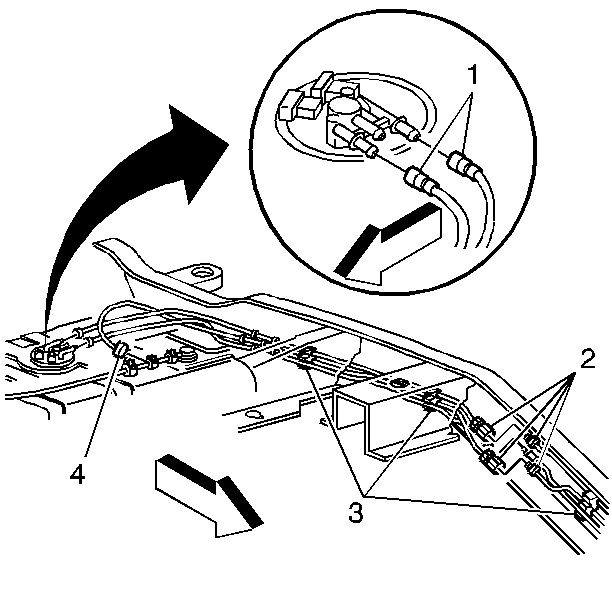
- Disconnect the fuel (1)
and vapor (4) pipes.
- Remove the fuel pipe unions in front of the crossmember (2).
- Remove the hardware retaining section of pipe to be replaced (3).
Note location of attaching hardware for installation.
- Remove the section of pipe and hoses.
- Remove rust or burrs from the engine compartment fuel pipes by
the following procedure:
| 11.1. | Use emery cloth in a radial motion with the fuel pipe end in order
to prevent damage to the O-ring sealing surface. |
| 11.2. | Using a clean shop towel, wipe off the male tube ends. |
| 11.3. | Inspect all the connectors for dirt and burrs. Clean or replace
the components/assemblies as required. |
Installation Procedure
Notice:
| • | Do not attempt to straighten kinked nylon pipes. Replace any kinked
nylon pipes in order to prevent damage to the vehicle. |
| • | Do not attempt to repair sections of nylon pipes. Replace damaged
nylon pipes. |
| • | Replace the vapor pipes with original equipment or parts that
meet GM specifications. |
| • | Replace the vapor hoses with original equipment or parts meeting
GM specifications. Use only reinforced fuel-resistant hose identified with
the word Fluoroelastomer or GM 6163M on the hose. |
- Connect the fuel feed and return pipes to the engine fuel pipes (1).
Notice: Use the correct fastener in the correct location. Replacement fasteners
must be the correct part number for that application. Fasteners requiring
replacement or fasteners requiring the use of thread locking compound or sealant
are identified in the service procedure. Do not use paints, lubricants, or
corrosion inhibitors on fasteners or fastener joint surfaces unless specified.
These coatings affect fastener torque and joint clamping force and may damage
the fastener. Use the correct tightening sequence and specifications when
installing fasteners in order to avoid damage to parts and systems.
- Connect the fuel
pipe attaching hardware (2).
Tighten
Fuel pipe attaching nuts to 27 N·m (20 lb ft)
using a back-up wrench.
- Position new fuel pipe harness in original location and fuel pipe
harness attaching hardware (2).
- Remove protective caps from one end of both fuel pipes.
Leave caps on other end of pipes to prevent dirt from entering.
- Apply a few drops of clean engine oil to the male connector tube
ends.
- Connect the fuel feed pipe to the fuel filter and the return pipe
to union (3).
- Connect the quick-connect
fittings at the fuel feed and return pipes (1) and the vapor pipes (4) at
the fuel sender assembly. Refer to Quick Connect Fitting(s) Service (Metal Collar)
or Quick Connect Fitting(s) Service (Plastic Collar)
.
- Connect the fuel pipe unions in front of the crossmember (2).
- Install the fuel tank and attaching hardware (3), if the tank
was removed.
- Tighten the fuel filler cap.
- Connect the negative battery cable.
- Check for fuel leaks.
| 12.1. | Turn the ignition switch to the ON position for 2 seconds. |
| 12.2. | Turn the ignition switch to the OFF position for 10 seconds. |
| 12.3. | Again, turn the ignition switch to the ON position. |
| 12.4. | Check for fuel leaks. |
Fuel Hose/Pipes Assembly Replacement Fuel Pipe Repair
Steel fuel lines - These are welded steel tubes, meeting
GM specifications 124-M, or its equivalent. The fuel feed line is 3/8 inches
diameter and the fuel return line is 5/16 inches diameter. Do not use copper
or aluminum tubing to replace steel tubing. Those materials do not have satisfactory
durability to withstand normal vehicle vibration.
Coupled hose - Do not repair the hoses. Replace them only as an assembly.
Uncoupled hose - Use only reinforced fuel resistant hose,
made of Fluoroelastomer material. Do not use a hose within 4 inches
(100 mm) of any part of the exhaust system, or within 10 inches
(2154 mm) of the catalytic converter. The hoses inside diameter must
match the outside diameter of the steel tubing.
Clamps - These are stainless steel, screw bank-type clamps, #2494772,
or equivalent.
Steel Fuel Line Repair
- Cut a piece of fuel hose 4 inches (100 mm) longer
than the section of line to be removed. If you remove more than 6 inches
(152 mm), use a combination of steel pipe and hose. The hose length
should not be more than 10 inches total.
- With a tube cutter, cut a section of the pipe to replace. Use
the first step to form a bead on the ends of the pipe and, also, on the new
section of pipe, if used.
- Slide the hose clamps onto the pipe and push the hose 2 inches
(51 mm) onto each portion of the fuel pipe. Tighten a clamp on each
side of the repair.
- Secure fuel line to the frame.
- Check for leaks.
