Removal Procedure
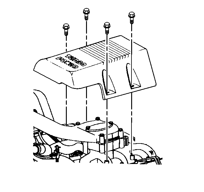
- Remove the upper intake manifold cover by loosening the four mounting bolts.
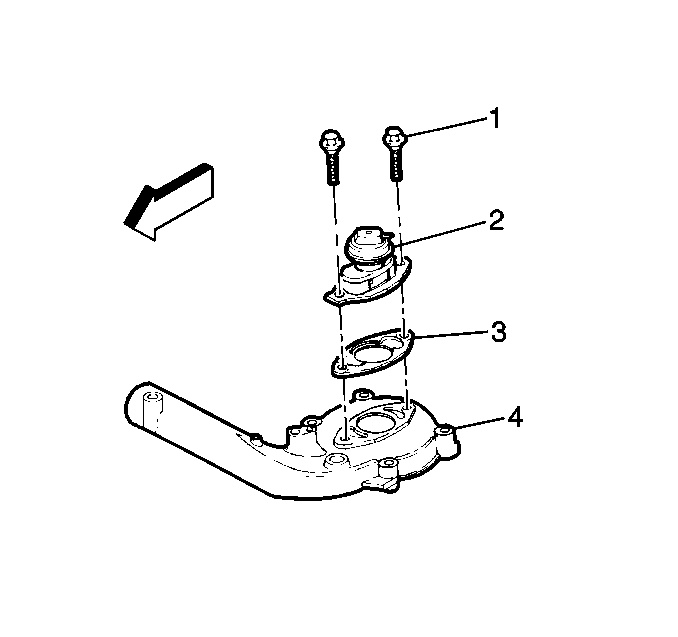
- Remove the vacuum hose from the EGR valve (2).
- Remove the EGR valve mounting bolts (1).
- Remove the EGR valve (2) and the gasket (3).


Installation Procedure
- Install the EGR valve (2) and gasket (3).
- Install EGR valve mounting bolts (1).
- Install the EGR valve vacuum hose.
- Install the upper intake manifold cover.
- Install the upper intake manifold cover bolts.
- Install negative battery cables.
- Start and idle engine.
- Reset ALM cells using scan tool (under special functions in scan tool).

Notice: Use the correct fastener in the correct location. Replacement fasteners must be the correct part number for that application. Fasteners requiring replacement or fasteners requiring the use of thread locking compound or sealant are identified in the service procedure. Do not use paints, lubricants, or corrosion inhibitors on fasteners or fastener joint surfaces unless specified. These coatings affect fastener torque and joint clamping force and may damage the fastener. Use the correct tightening sequence and specifications when installing fasteners in order to avoid damage to parts and systems.
Tighten
Tighten bolts to 25 N·m (18 lb ft).

Tighten
Tighten the bolts to 11 N·m (100 lb in).
Important: If the ALM cells are not reset, a poor driveability, heavy black smoke and EGR DTCs will exist until vehicle has been driven. The ALM cells will adjust to normal settings after the vehicle has been driven (mileage will vary) and all DTCs are cleared.
