Circuit Description
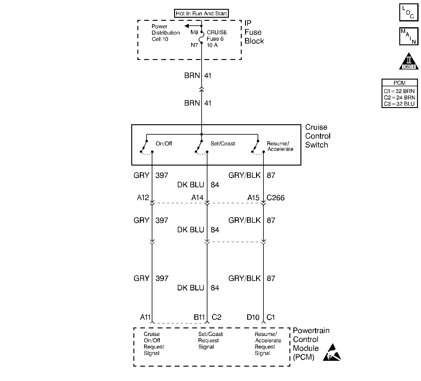
The cruise set/coast switch is an input to the fuel control portion of the PCM. These inputs allow the PCM to control and hold a requested speed. The cruise set/coast switch sends an ignition voltage signal to the PCM when the set/coast switch is ON.
Conditions for Running the DTC
| • | The PCM performs this DTC diagnostic continuously. |
| • | The ignition switch in the ON position. |
Conditions for Setting the DTC
Ignition voltage on set/coast request signal circuit when the cruise control ON/OFF switch in the OFF position.
or
| • | Set/Coast request switch ON for longer than 25.5 seconds when the Cruise Control ON/OFF switch in the ON position. |
| • | All of the diagnostic set conditions met for 2 seconds. |
Action Taken When the DTC Sets
| • | The PCM disallows all cruise control inputs. |
| • | TCC shift schedules may be affected. |
| • | The PCM will not illuminate the malfunction indicator lamp (MIL). |
| • | The PCM records the operating conditions at the time the diagnostic fails. This information stores in the Failure Records. |
Conditions for Clearing the MIL/DTC
| • | A History DTC clears after forty consecutive warm-up cycles, if this or any other emission related diagnostic does not report any failures |
| • | The use of a scan tool. |
Diagnostic Aids
If the set/coast switch is stuck in the ON position or the driver is holding the set/coast switch ON for longer than 25.5 seconds, DTC P0568 will set. DTC P0568 only checks the signal circuit for a short to voltage.
Test Description
Number(s) below refer to the step number(s) on the Diagnostic Table.
-
This step determines if the signal circuit is shorted to voltage.
-
This step determines if the PCM or switch is at fault.
Step | Action | Value(s) | Yes | No |
|---|---|---|---|---|
1 |
Important: Before clearing any DTCs, use the scan tool Capture Info to save freeze frame and failure records for reference, as the Scan tool loses data when using the Clear Info function. Was the Powertrain On-Board Diagnostic (OBD) System Check performed? | -- | ||
2 |
Does the scan tool display the Set switch ON? | -- | ||
3 |
Is the test light ON? | -- | ||
4 | The DTC is intermittent. If no additional DTCs are stored, refer to Diagnostic Aids. If additional DTCs were stored refer to the applicable DTC table(s) first. Are any additional DTCs stored? | -- | Go to the Applicable DTC Table | Go to Diagnostic Aids |
5 |
Is the action complete? | -- | -- | |
6 | Replace the PCM. Important: The new PCM must be programmed. Refer to Powertrain Control Module Replacement/Programming . Is the action complete? | -- | -- | |
7 |
Does the Scan Tool indicate the diagnostic Passed? | -- | ||
8 | Does the Scan tool display any additional undiagnosed DTCs? | -- | Go to the Applicable DTC Table | System OK |
