For 1990-2009 cars only
Tools Required
J 24319-B Universal Steering Linkage Puller
Removal Procedure
- Raise the vehicle. Support the vehicle with suitable safety stands.
- Remove the tire and wheel. Refer to Tire and Wheel Removal and Installation in Tires and Wheels.
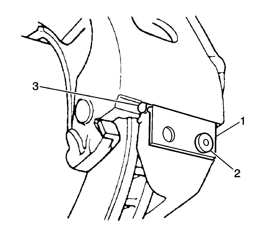
- Remove the bolt (2) retaining the key support to the caliper (1).
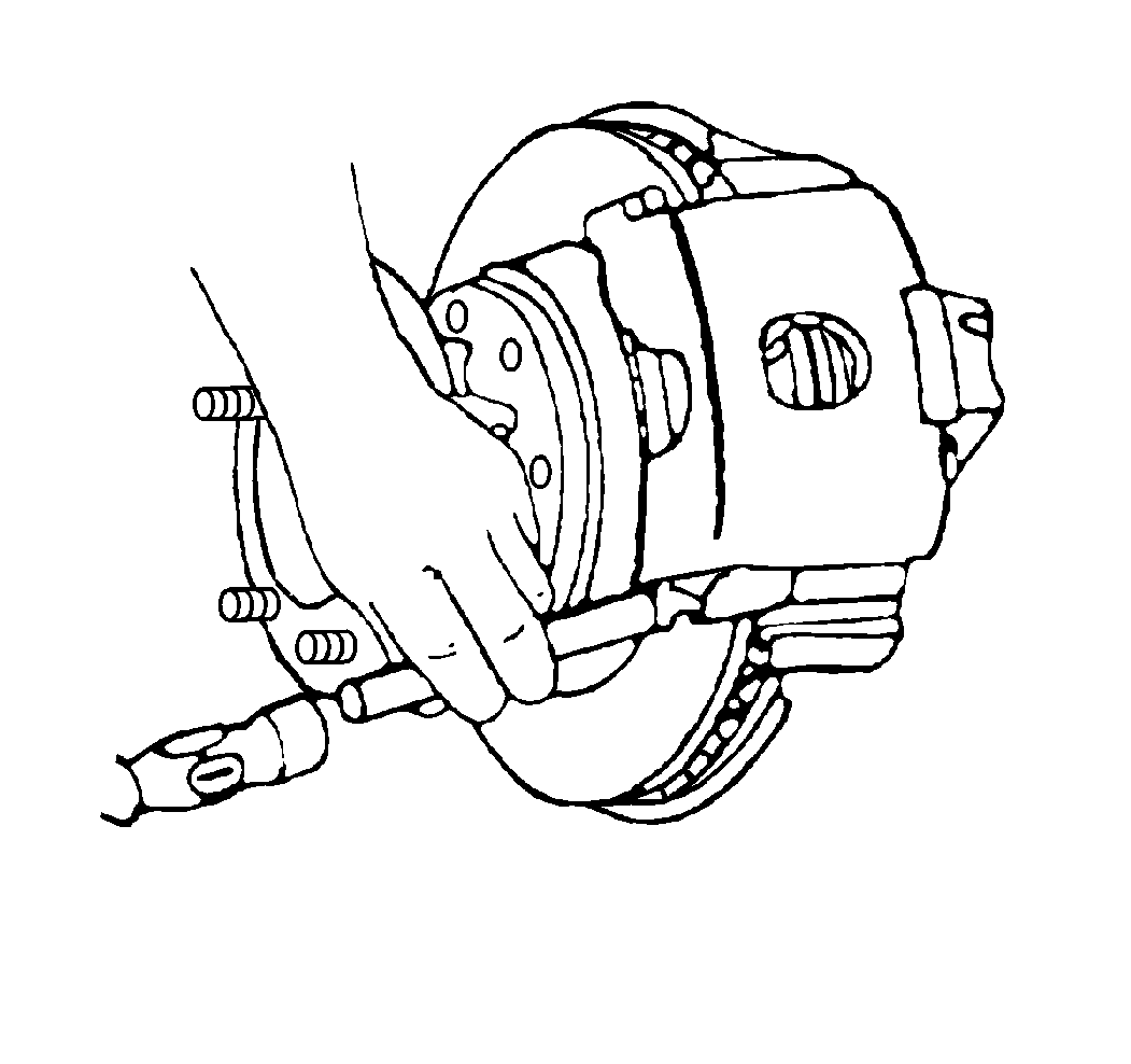
- Remove the support key and the spring using a brass punch and a hammer to drive out the support key.
- Remove the caliper assembly.
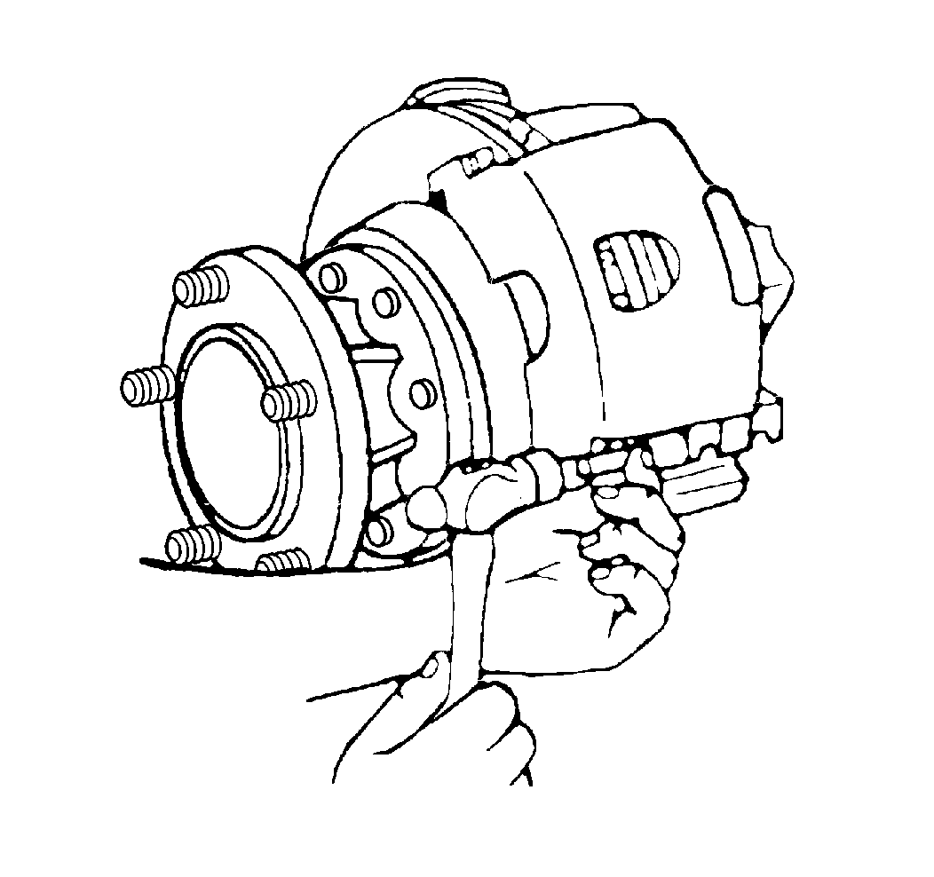
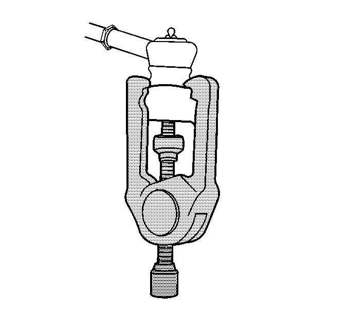
- Remove the cotter pin and nut retaining the tie rod to the steering arm.
- Using the J 24319-B remove the tie rod from the steering arm.
- Remove the brake rotor. Refer to Brake Rotor Replacement in Disc Brakes.
- Remove the bolts retaining the brake caliper mounting bracket.
- Remove the brake caliper dust shield.
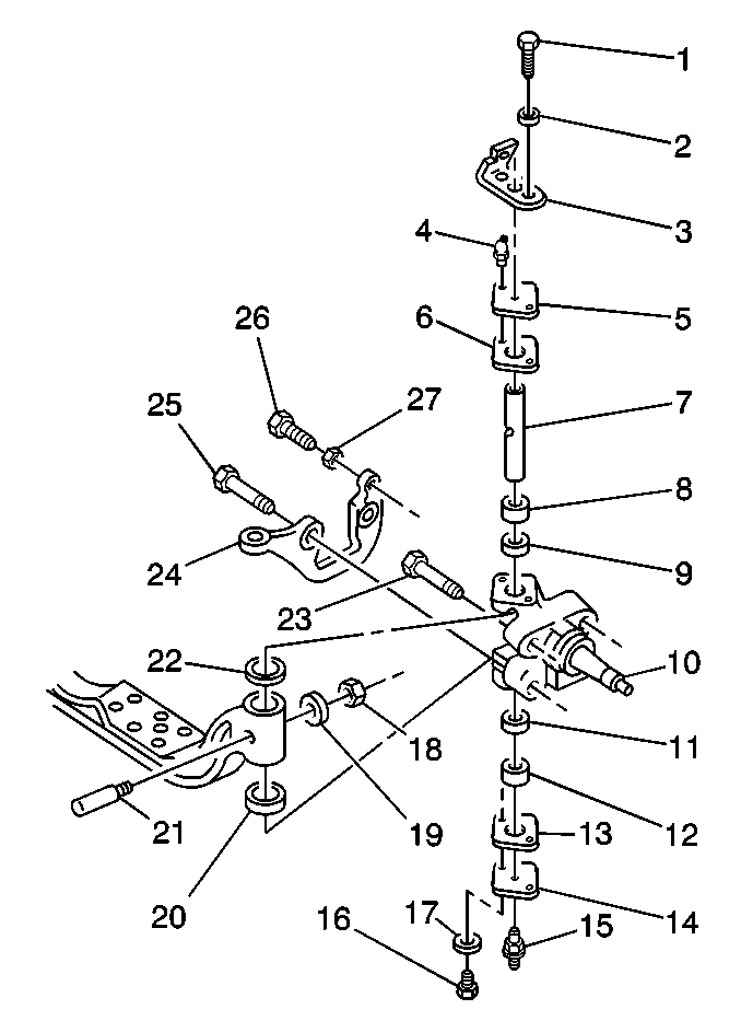
- Remove the upper steering knuckle cap (5) and gasket (6).
- Remove the lower steering knuckle cap (14) and gasket (13).
- Remove the king pin (7) lock pin (21).
- Remove the steering knuckle (10) from the axle.
- Remove the dust seal, shim and the thrust bearing.
| • | Using a drift, drive out the king pins. |
| • | The spacers and the bushings (8, 12) will also come out. |
Installation Procedure
- New knuckles have bushings already installed and reaming is not needed. If reusing the original knuckles, install the bushings (8,12). ream the bushings to between 29.982 - 30.022 mm (1.1804 - 1.1820 in).
- Install the steering knuckle (10).
- Install the thrust bearing shim and dust seal.
- Install the king pin and the lock pin (21).
- Install the lock pin retaining nut and washer.
- Install the gaskets (6, 13).
- Install the upper and lower steering knuckle caps (5, 14).
- Check and if needed, adjust the king pin preload. Refer to King Pin Bearing Preload .
- Install the brake caliper dust shield.
- Install the brake rotor. Refer to Brake Rotor Replacement in Disc Brakes.
- Install the brake caliper mounting bracket and bolts.
- Install the brake caliper.
- Install the key support to the caliper.
- Install the bolt (1) retaining the key support to the caliper.
- Lubricate the king pins.
- Install the tire and wheel. Refer to Tire and Wheel Removal and Installation in Tires and Wheels.
- Remove the safety stands.
- Lower the vehicle.

An adjustable reamer is available from industrial and automotive tool suppliers.
Lubricate the thrust bearing. Refer to Fluid and Lubricant Recommendations in Maintenance and Lubrication.
| • | Lubricate the king pin. Refer to Fluid and Lubricant Recommendations in Maintenance and Lubrication. |
| • | Insert the spacers in the correct order. |
Notice: Refer to Fastener Notice in the Preface section.
Tighten
Tighten the lock pin retaining nut to 40 N·m (29 lb ft).
Tighten
Tighten the brake caliper mounting bolts to 105 N·m (78 lb ft).

Tighten
Tighten the caliper retaining bolt to 20 N·m (15 lb ft).
