Brake Rotor Replacement K Models Below 8600 GVW
Removal Procedure
- Raise the vehicle. Support the vehicle with suitable safety stands.
- Remove the tire and wheel assembly. Refer to Tire and Wheel Removal and Installation in Tires and Wheels.
- Remove the brake caliper. Refer to Brake Caliper Replacement .
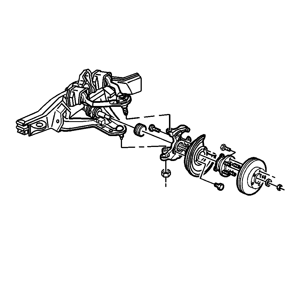
- Remove the rotor.
- Inspect all of the parts. Replace the parts as necessary.
Installation Procedure
- Install the rotor to the hub and bearing assembly.
- Install the brake caliper. Refer to Brake Caliper Replacement .
- Install the tire and wheel assembly. Refer to Tire and Wheel Removal and Installation in Tires and Wheels.
- Lower the vehicle.
- Depress the brake pedal.

Brake Rotor Replacement K Models Above 8600 GVW
Removal Procedure
- Raise the vehicle. Refer to Lifting and Jacking the Vehicle in general Information.
- Remove the tire and wheel assembly. Refer to Tire and Wheel Removal and Installation in Tires and Wheels.
- Remove the brake caliper. Refer to Brake Caliper Replacement .
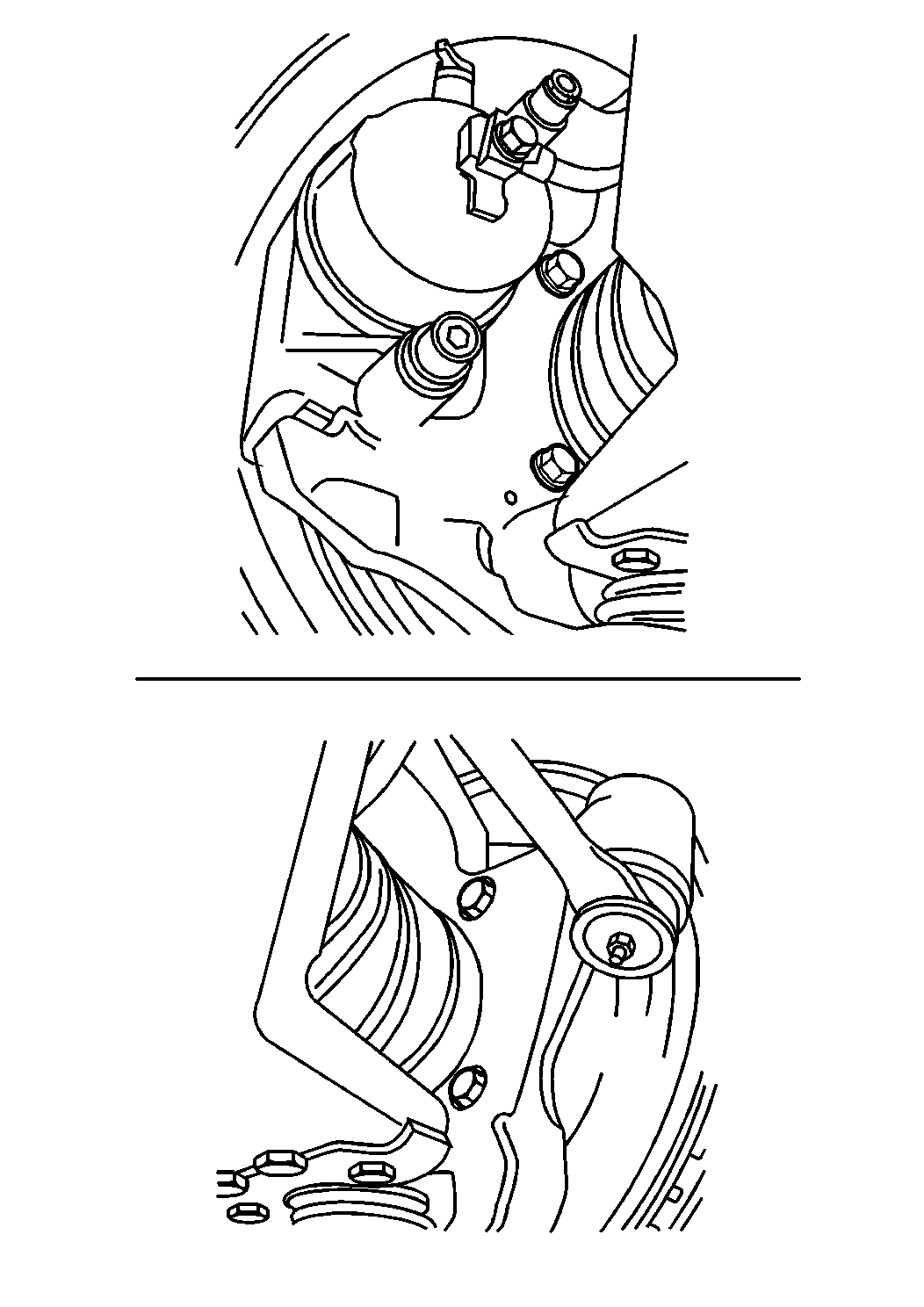
- Remove the nut.
- Remove the hub/rotor retaining bolts.
- Remove the rotor assembly.
- Inspect all of the parts. Replace the parts as necessary.

Installation Procedure
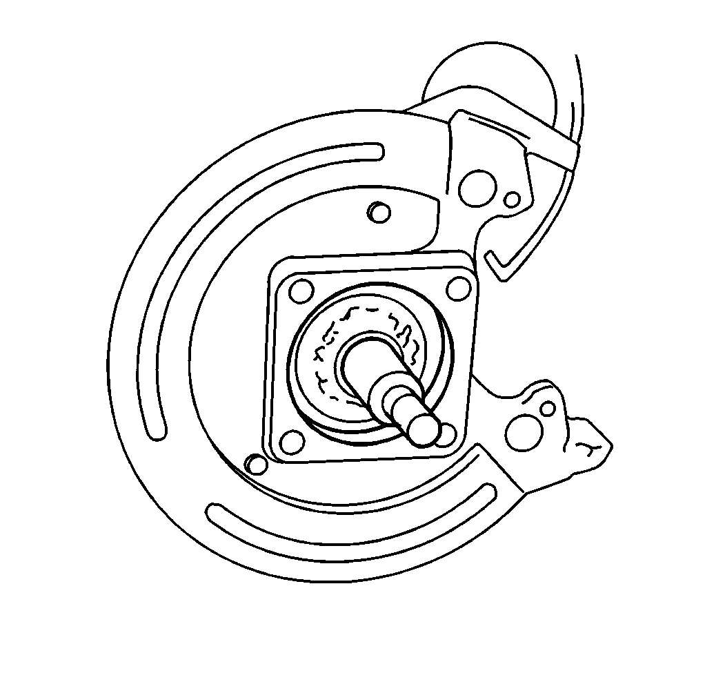
- Install the hub/rotor to the hub and bearing assembly.
- Install the rotor and hub assembly to the axle.
- Install the brake caliper. Refer to Brake Caliper Replacement .
- Install the tire and wheel assembly. Refer to Tire and Wheel Removal and Installation in Tires and Wheels.
- Lower the vehicle.Refer to Lifting and Jacking the Vehicle
- Depress the brake pedal.

Notice: Use the correct fastener in the correct location. Replacement fasteners must be the correct part number for that application. Fasteners requiring replacement or fasteners requiring the use of thread locking compound or sealant are identified in the service procedure. Do not use paints, lubricants, or corrosion inhibitors on fasteners or fastener joint surfaces unless specified. These coatings affect fastener torque and joint clamping force and may damage the fastener. Use the correct tightening sequence and specifications when installing fasteners in order to avoid damage to parts and systems.
Tighten
| • | Tighten the bolts to 180 N·m (133 lb ft). |
| • | Tighten the nut to 225 N·m (165 lb ft). |
Brake Rotor Replacement C3500HD (Front)
Removal Procedure
- Block the wheels.
- Apply the parking brake.
- Raise the vehicle. Refer to Lifting and Jacking the Vehicle in General Information.
- Remove the tire and wheel. Refer to Tire and Wheel Removal and Installation in Tires and Wheels:
- Remove the brake caliper. Refer to Brake Caliper Replacement in Hydraulic Brakes.
- Remove the brake rotor.
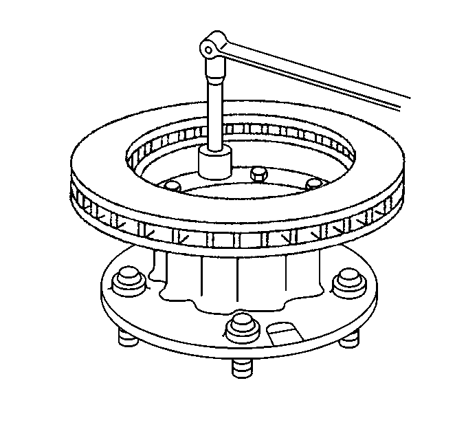
- Remove the bolts that mount the front brake rotor to the hub.
- Remove the brake rotor from the hub.
Installation Procedure
- Install the brake rotor to the hub.
- Install the bolts that mount the brake rotor to the hub, or the wheel.
- Apply 272 Threadlocker GM P/N 12345493, or the equivalent, to the threads of each brake rotor bolt.
- Install the brake rotor.
- Inspect the brake rotor for runout after installation. Refer to Brake Rotor Lateral Runout Check .
- Clean both sides of the brake rotor with Brake Parts Cleaner GM P/N 12345754 or the equivalent.
- Clean the grease cap or cover.
- Coat the inside of the grease cap with new wheel grease. Do not fill the cap.
- Install the brake caliper. Refer to Brake Caliper Replacement .
- Install the tire and wheel. Refer to Tire and Wheel Removal and Installation .
- Lower the vehicle.
- Pump the brake pedal several times in order to ensure the pedal is firm and the brake pads are adjusted.
- Remove the blocks.
Notice: Any new rotor must have the protective coating removed from the friction surfaces before being placed in service. Remove the protective coating using denatured alcohol or an equivalent brake cleaner, and wipe the surface clean with clean cloths. Do not use gasoline, kerosene, or other oil base solvents which may leave an oily residue. This residue is damaging to the brake lining and is flammable.

Notice: Use the correct fastener in the correct location. Replacement fasteners must be the correct part number for that application. Fasteners requiring replacement or fasteners requiring the use of thread locking compound or sealant are identified in the service procedure. Do not use paints, lubricants, or corrosion inhibitors on fasteners or fastener joint surfaces unless specified. These coatings affect fastener torque and joint clamping force and may damage the fastener. Use the correct tightening sequence and specifications when installing fasteners in order to avoid damage to parts and systems.
Tighten
Tighten the brake rotor bolts (5/8 in OD-5 bolt pattern) to 256 N·m
(189 lb ft).
Important: Ensure that the threads are clean and greaseless before applying the threadlocker.
Caution: Do not move the vehicle until a firm brake pedal is obtained. Failure to obtain a firm pedal before moving vehicle may result in personal injury.
Important: Check the level of the brake fluid in the master cylinder reservoir after pumping the brake pedal.
Brake Rotor Replacement C3500HD (Rear)
Removal Procedure
- Block the wheels.
- Apply the parking brake.
- Raise the vehicle. Refer to Lifting and Jacking the Vehicle in General Information.
- Remove the tire and wheel. Refer to Tire and Wheel Removal and Installation in Tires and Wheels:
- Remove the brake caliper. Refer to Brake Caliper Replacement .
- Remove the brake rotor (with the hub).
- Remove the bolts that mount the front brake rotor to the hub.
- Remove the brake rotor from the hub.
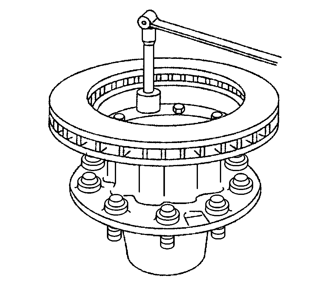
Installation Procedure
- Install the brake rotor to the hub.
- Install the bolts that mount the brake rotor to the hub.
- Apply 272 Threadlocker GM P/N 12345493, or the equivalent, to the threads of each brake rotor bolt.
- Install the brake rotor (with the hub).
- Inspect the brake rotor for runout after installation. Refer to Brake Rotor Lateral Runout Check .
- Clean both sides of the brake rotor with Brake Parts Cleaner GM P/N 12345754 or the equivalent.
- Clean the grease cap or cover .
- Coat the inside of the grease cover with new wheel grease. Do not fill the cap.
- Install the brake caliper. Refer to Brake Caliper Replacement .
- Install the tire and wheel.
- Lower the vehicle.
- Pump the brake pedal several times in order to ensure the pedal is firm and the brake pads are adjusted.
- Remove the blocks.
Notice: Any new rotor must have the protective coating removed from the friction surfaces before being placed in service. Remove the protective coating using denatured alcohol or an equivalent brake cleaner, and wipe the surface clean with clean cloths. Do not use gasoline, kerosene, or other oil base solvents which may leave an oily residue. This residue is damaging to the brake lining and is flammable.

Notice: Use the correct fastener in the correct location. Replacement fasteners must be the correct part number for that application. Fasteners requiring replacement or fasteners requiring the use of thread locking compound or sealant are identified in the service procedure. Do not use paints, lubricants, or corrosion inhibitors on fasteners or fastener joint surfaces unless specified. These coatings affect fastener torque and joint clamping force and may damage the fastener. Use the correct tightening sequence and specifications when installing fasteners in order to avoid damage to parts and systems.
Tighten
Tighten the brake rotor bolts (9/16 in OD-10 bolt pattern) to
152 N·m (112 lb ft).
Important: Ensure that the threads are clean and greaseless before applying the threadlocker.
Caution: Do not move the vehicle until a firm brake pedal is obtained. Failure to obtain a firm pedal before moving vehicle may result in personal injury.
Important: Check the level of the brake fluid in the master cylinder reservoir after pumping the brake pedal.
