Catalytic Converter Replacement Diesel
Removal Procedure
- Raise and suitably support the vehicle. Refer to Lifting and Jacking the Vehicle in General Information.
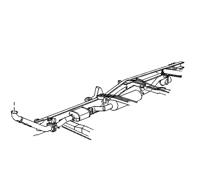
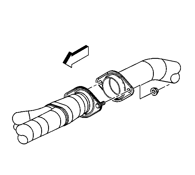
- Remove the front exhaust pipe flange stud nuts from the front of the catalytic converter assembly.
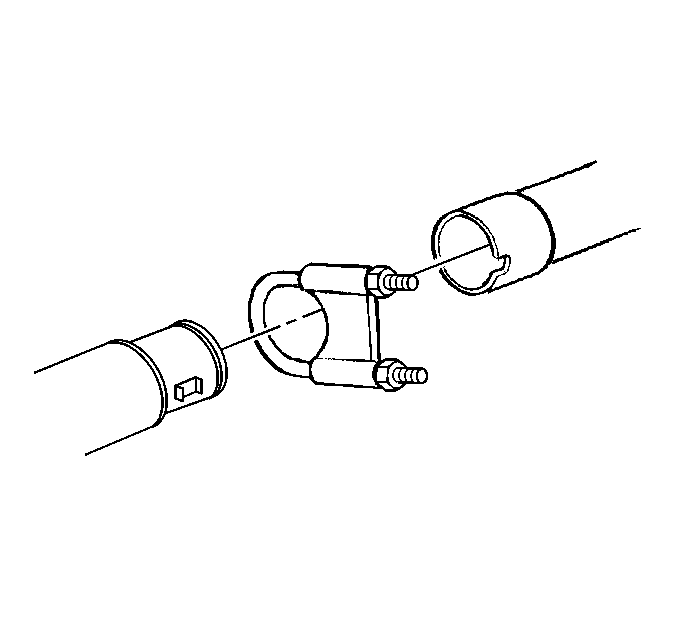
- Remove the U-bolt from the rear of the catalytic converter assembly.
- Remove the catalytic converter from the muffler assembly.
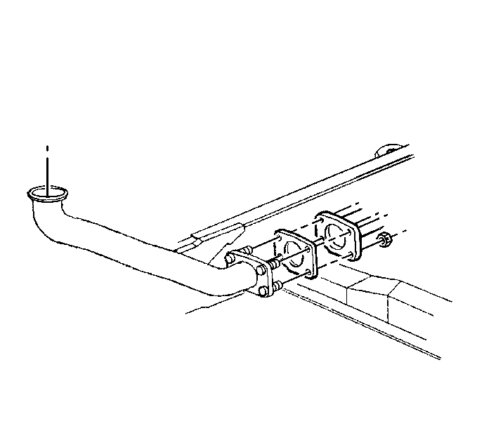
Remove the clamp from the exhaust manifold pipe.
Installation Procedure
- Install a new flange gasket and the catalytic converter to the front exhaust pipe flange studs.
- Install the nuts to the exhaust pipe flange studs.
- Install a new U-bolt to the rear of the catalytic converter.
- Check for clearance and alignment.
- Lower the vehicle.


Notice: Use the correct fastener in the correct location. Replacement fasteners must be the correct part number for that application. Fasteners requiring replacement or fasteners requiring the use of thread locking compound or sealant are identified in the service procedure. Do not use paints, lubricants, or corrosion inhibitors on fasteners or fastener joint surfaces unless specified. These coatings affect fastener torque and joint clamping force and may damage the fastener. Use the correct tightening sequence and specifications when installing fasteners in order to avoid damage to parts and systems.
Tighten
Tighten the nuts to 64 N·m (47 lb ft).

Tighten
Tighten the nuts to 42 N·m (31 lb ft).
Install the clamp to the exhaust manifold pipe.
Tighten
Tighten the nut to 12 N·m ( 106 lb in).
Catalytic Converter Replacement Gas, Export
Removal Procedure
- Raise and suitably support the vehicle. Refer to Lifting and Jacking the Vehicle in General Information.
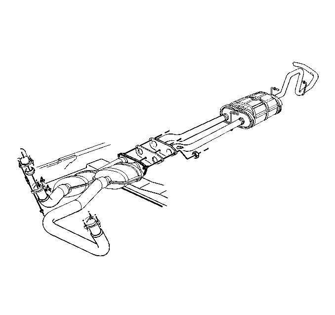
- Remove the nuts from the Y-pipe flat flange.
- Remove the muffler and the catalytic converter assembly.
- Remove the nuts, studs, and flange seals from the Y-pipe and the exhaust manifold.
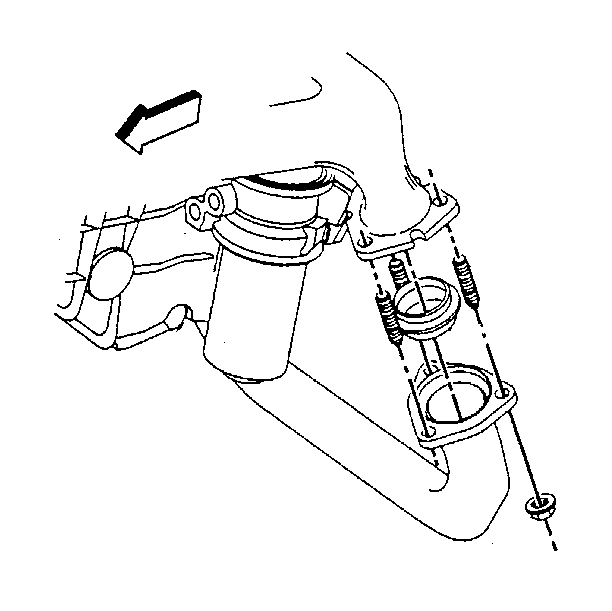
Installation Procedure
- Install the new flange seals.
- Install the new studs.
- Install the new nuts connecting the Y-pipe, catalytic converter assembly to the exhaust manifold.
- Position the Y-pipe and the catalytic converter assembly to the flat flange.
- Install the nuts to the flat flange studs.
- Check for clearance and alignment.
- Lower the vehicle.

Notice: Use the correct fastener in the correct location. Replacement fasteners must be the correct part number for that application. Fasteners requiring replacement or fasteners requiring the use of thread locking compound or sealant are identified in the service procedure. Do not use paints, lubricants, or corrosion inhibitors on fasteners or fastener joint surfaces unless specified. These coatings affect fastener torque and joint clamping force and may damage the fastener. Use the correct tightening sequence and specifications when installing fasteners in order to avoid damage to parts and systems.
Tighten
Tighten the studs to 22 N·m (16 lb ft).
Tighten
Tighten the nuts to 64 N·m (47 lb ft).

Tighten
Tighten the nuts to 64 N·m (47 lb ft).
Catalytic Converter Replacement Gas, 8600 lb and above (GVWR)
Removal Procedure
- Raise and suitably support the vehicle. Refer to Lifting and Jacking the Vehicle .
- Disconnect the oxygen sensor electrical connections.
- Remove the nuts from the Y-pipe flat flange.
- Remove the nuts, studs and flange seals from the Y-pipe and the exhaust manifold.
- Remove the Y-pipe and the catalytic converter assembly.
- Remove the muffler and the catalytic converter assembly.
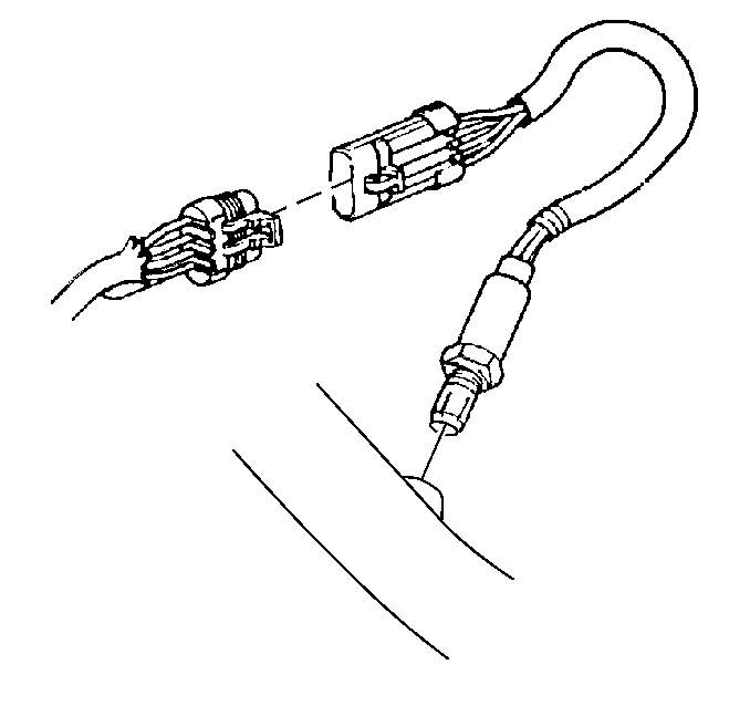
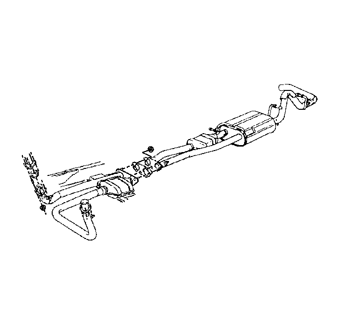


Installation Procedure
- Install the flange seals, the studs and the nuts connecting the Y-pipe, catalytic converter assembly to the exhaust manifold.
- Install the muffler and the catalytic converter assembly.
- Position the Y-pipe and the catalytic converter assembly to the flat flange.
- Install the nuts to the flat flange studs.
- Connect the oxygen sensor electrical connections.
- Check for clearance and alignment.
- Lower the vehicle.

Notice: Use the correct fastener in the correct location. Replacement fasteners must be the correct part number for that application. Fasteners requiring replacement or fasteners requiring the use of thread locking compound or sealant are identified in the service procedure. Do not use paints, lubricants, or corrosion inhibitors on fasteners or fastener joint surfaces unless specified. These coatings affect fastener torque and joint clamping force and may damage the fastener. Use the correct tightening sequence and specifications when installing fasteners in order to avoid damage to parts and systems.
Tighten
Tighten the studs to 22 N·m (16 lb ft).
Tighten
Tighten the nuts to 64 N·m (47 lb ft).

Tighten
Tighten the nuts to 64 N·m (47 lb ft).

Catalytic Converter Replacement 4.8L and 5.3L Engines
Removal Procedure
- Raise and suitably support the vehicle. Refer to Lifting and Jacking the Vehicle in General Information.
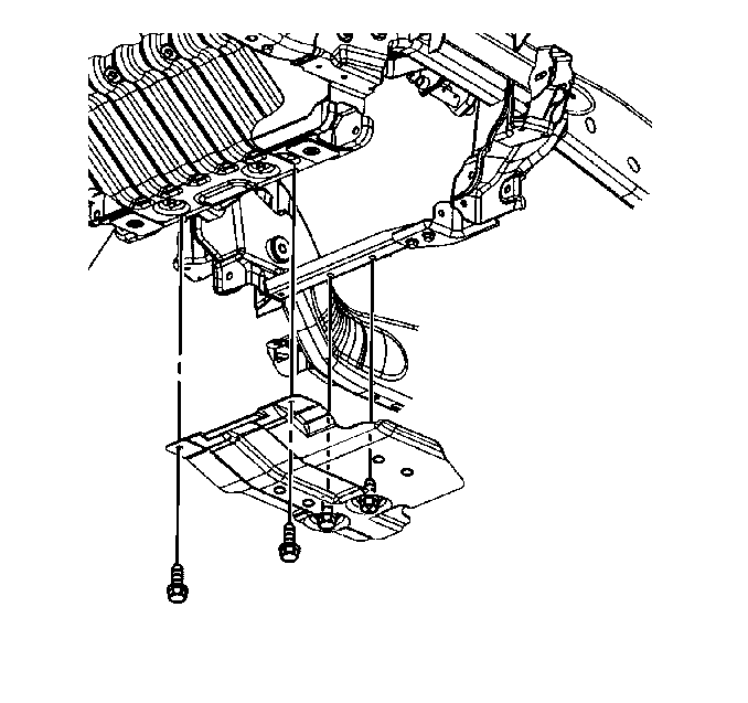
- Remove the engine shield bolts and shield, if necessary.
- Remove the oil pan skid plate bolts and plate, if necessary.
- Support the transmission with a suitable transmission jack.
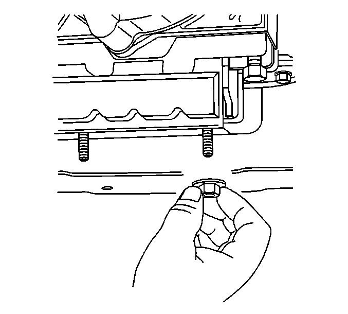
- Remove the transmission mount to transmission support nuts.
- Raise the transmission off the transmission support.
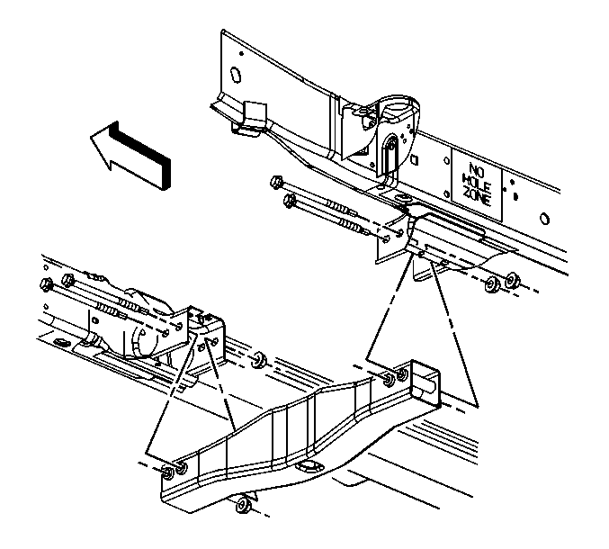
- Remove the transmission support crossmember bolts and nuts.
- Remove the transmission support crossmember.
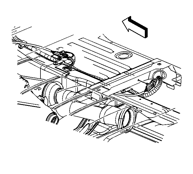
- Unclip the oxygen sensor connection from the floor reinforcement.
- Remove the clip from around the engine harness and the oxygen sensor pigtail.
- Disconnect the connector position assurance (CPA) retainers.
- Disconnect the oxygen sensor electrical connectors.
- Unclip the oxygen sensors electrical connectors from the following:
- Disconnect the CPA retainers.
- Disconnect the oxygen sensor electrical connectors (1, 2).
- Remove the left exhaust manifold pipe nuts.
- Remove the right exhaust manifold pipe nuts.
- Remove the exhaust muffler nuts.
- Remove the catalytic converter.
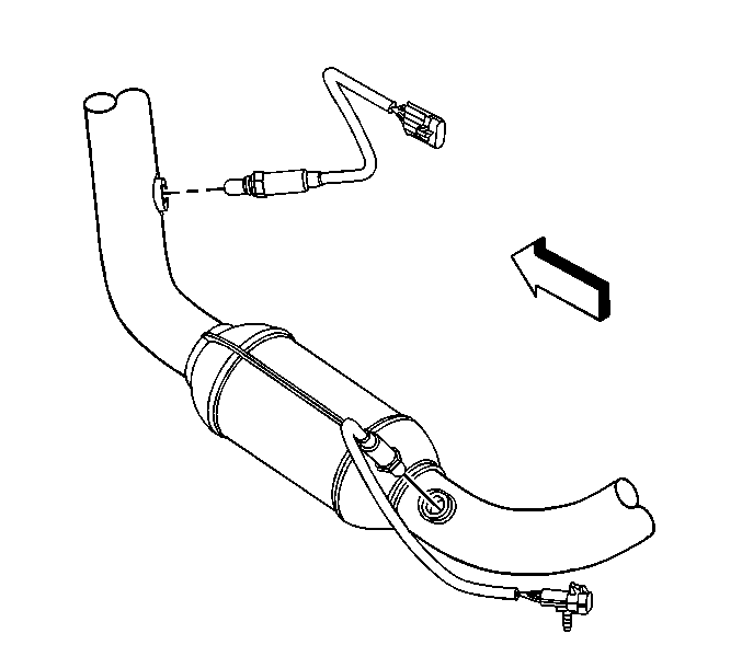
- Remove the oxygen sensors if the catalytic converter is to be replaced.
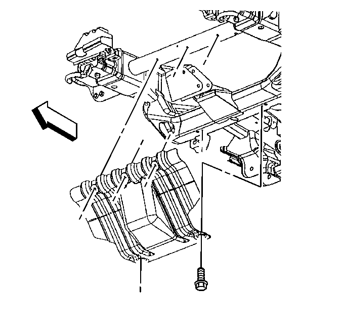
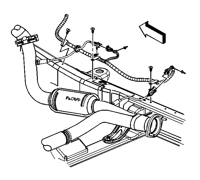
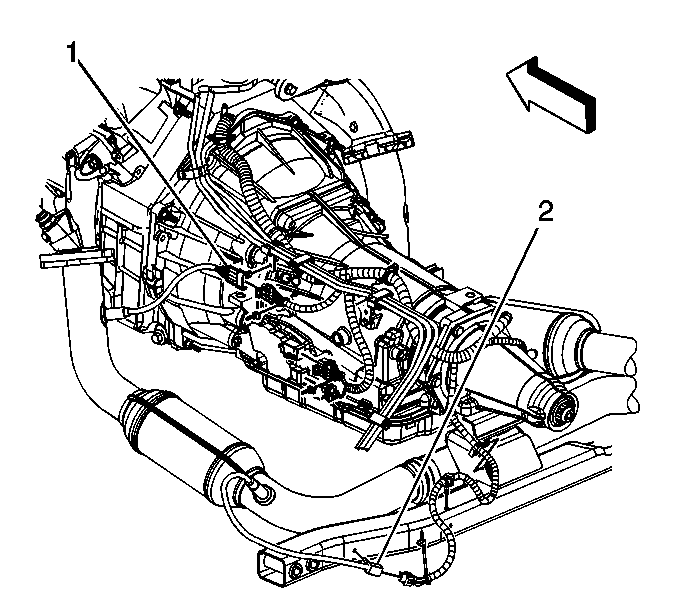
| • | Hose clip |
| • | Transmission crossmember |
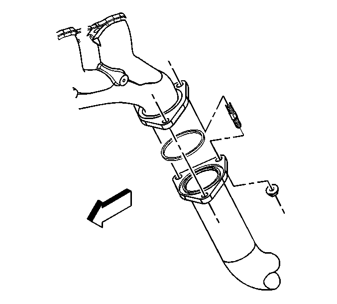
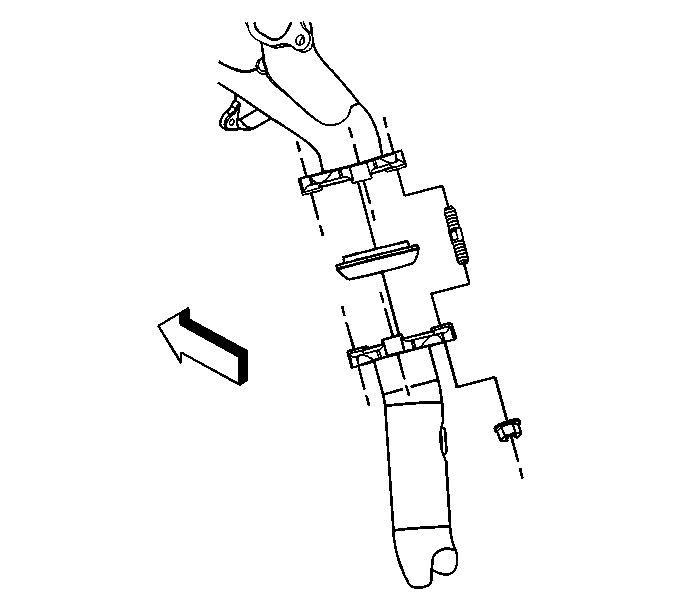
Installation Procedure
- If the catalytic converter was replaced, perform the following:
- Install the catalytic convertor.
- Install NEW exhaust manifold pipe seals to the exhaust manifolds.
- Install the right exhaust manifold pipe nuts until sung.
- Install the left exhaust manifold pipe nuts until snug.
- Tighten the right and left exhaust manifold pipe nuts.
- Install the exhaust muffler nuts.
- Connect the oxygen sensor electrical connectors (1, 2).
- Connect the CPA retainers.
- Clip the oxygen sensors electrical connectors to the following:
- Connect the oxygen sensor electrical connectors.
- Connect the CPA retainers.
- Install the clip around the engine harness and the oxygen sensor pigtail.
- Clip the oxygen sensor connection to the floor reinforcement.
- Install the transmission support crossmember.
- Install the transmission support crossmember bolts and nuts.
- Lower the transmission onto the transmission support.
- Install the transmission mount to transmission support nuts.
- Remove the transmission jack.
- Install the oil pan skid plate and bolts, if necessary.
- Install the engine shield and bolts, if necessary.
- Lower the vehicle.
Notice: Refer to Fastener Notice in the Preface section.

| 1.1. | Apply anti-seize compound GM P/N 12377953 or equivalent to the threads of the old oxygen sensors. |
| 1.2. | Install the oxygen sensors. |
Tighten
Tighten the oxygen sensors to 42 N·m (31 lb ft).


Tighten
Tighten the nuts to 50 N·m (39 lb ft).

Tighten
Tighten the nuts to 40 N·m (30 lb ft).

| • | Hose clip |
| • | Transmission crossmember |


Tighten
Tighten the bolts to 95 N·m (70 lb ft).

Tighten
Tighten the nuts to 40 N·m (30 lb ft).

Tighten
Tighten the bolts to 20 N·m (15 lb ft).

Tighten
Tighten the bolts to 20 N·m (15 lb ft).
