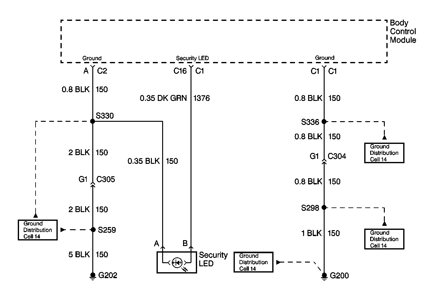
Circuit Description
Voltage is supplied to the security LED indicator lamp on the console from the body control module (BCM) through the following areas:
| • | The IGN B Fuse in the underhood fuse block 7 |
| • | CKT 1376 |
Voltage is supplied by the body control module (BCM) through CKT 1376 to the security LED indicator lamp when the ignition switch is in one of the following positions:
| • | BULB TEST |
| • | RUN |
The security LED indicator lamp illuminates for approximately 5 seconds in order to verify the circuit operation.
The BCM also utilizes the security LED indicator lamp in order to display the diagnostic trouble code (DTC) flash codes by supplying voltage to CKT 1376.
Conditions for Setting the DTC
Diagnostic trouble codes (DTC) 12 is always set and displayed when the body control module (BCM) is in the diagnostic mode. This indicates that the diagnostic function is in progress. If DTCs do not display when the BCM is in the diagnostic mode, refer to the following diagnostic chart.
Test Description
The number(s) below refer to the step number(s) on the diagnostic table.
-
This step tests the security LED indicator lamp operation at the BULB TEST.
-
This step attempts to enter the BCM diagnostic mode.
-
This step tests for voltage at the security LED indicator.
-
This step tests the circuit 1376.
-
This step tests for an open in the ground circuit.
-
This step checks for an open in the ground circuit 150.
-
This step requires the security LED replacement.
-
This steps requires replacement of the BCM.
Step | Action | Values | Yes | No | ||||||
|---|---|---|---|---|---|---|---|---|---|---|
1 | Turn the ignition switch to the RUN position. Does the security LED indicator illuminate? | -- | Go to Step 2 | Go to Step 3 | ||||||
2 | Attempt to enter the body control module (BCM) diagnostic mode. Does the security LED indicator flash DTCs? | -- | System OK | Go to Step 8 | ||||||
3 |
Is the voltage as specified? | B+ | Go to Step 5 | Go to Step 4 | ||||||
4 |
Did you find and correct the condition? | -- | System OK | Go to Step 8 | ||||||
5 | Using a DMM check for continuity at security LED indicator connector terminal A to ground Is continuity present? | -- | Go to Step 7 | Go to Step 6 | ||||||
6 | Repair for an open. Did you complete the repair? | -- | System OK | -- | ||||||
7 | Replace the security LED. Did you complete the repair? | -- | System OK | -- | ||||||
8 | Replace BCM. Is repair complete? | -- | System OK | -- |
