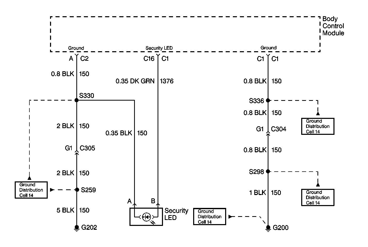
Circuit Description
The body control module (BCM) provides a 12 volt output to illuminate the security LED indicator lamp on the center console.
Conditions for Setting the DTC
The security LED indicator lamp CKT 1376 has been detected by the BCM to be open or shorted to ground for greater than 50 milliseconds.
Action Taken When the DTC Sets
| • | DTC 25 will set. |
| • | The security LED indicator lamp will not illuminate. |
Conditions for Clearing the MIL/DTC
The fault is corrected and the DTC memory clearing procedure is completed.
Diagnostic Aids
If the only DTC that flashes is a history code (DTC 35), the problem may be intermittent. Perform the test shown while "wiggling the wiring and connectors. This can often cause the fault to appear. Test for poor connections at the BCM connector, which could cause an open or and intermittent fault. Refer to Intermittent /History DTCs.
Test Description
The number(s) below refer to the step number(s) on the diagnostic table.
-
This step tests the security LED indicator lamp operation at the BULB TEST.
-
This step attempts to enter the BCM diagnostic mode.
-
This step tests for voltage at the security LED indicator.
-
This step tests for a poor connection at the BCM.
-
This step tests for an open in the ground circuit.
-
This step checks for an open in the ground circuit 150 between the BCM and G202.
-
This step requires a repair to CKT 150.
-
This steps requires replacement of the BCM.
Step | Action | Value(s) | Yes | No |
|---|---|---|---|---|
1 | Turn the ignition switch to the RUN position. Does the security LED indicator illuminate? | -- | ||
2 | Attempt to enter the body control module (BCM) diagnostic mode. Does the security LED indicator flash DTCs? | -- | System OK | -- |
3 |
Is continuity present? | -- | ||
4 | Test for a poor connection at BCM connector C1 terminal C16. Is the symptom still present? | -- | System OK | |
5 | Using a DMM check for continuity at security LED indicator connector terminal A to ground Is continuity present? | -- | ||
6 | Check for an open or poor connection in CKT 150, between the BCM connector C2 terminal A and C305. Was a repair made? | -- | System OK | |
7 | Repair the open in CKT 150, between the security LED indicator terminal A and G202. Is the repair complete? | -- | System OK | |
8 | Replace BCM. Is repair complete? | -- | System OK | -- |
