Removal Procedure
Caution: Unless directed otherwise, the ignition and start switch must be in the OFF or LOCK position, and all electrical loads must be OFF before servicing
any electrical component. Disconnect the negative battery cable to prevent an electrical spark should a tool or equipment come in contact with an exposed electrical terminal. Failure to follow these precautions may result in personal injury and/or damage to
the vehicle or its components.
- Disconnect
the battery negative cable. Refer to
Battery Negative Cable Disconnection and Connection
in Engine Electrical.
- Drain the engine coolant. Refer to
Cooling System Draining and Filling
in Engine Cooling.
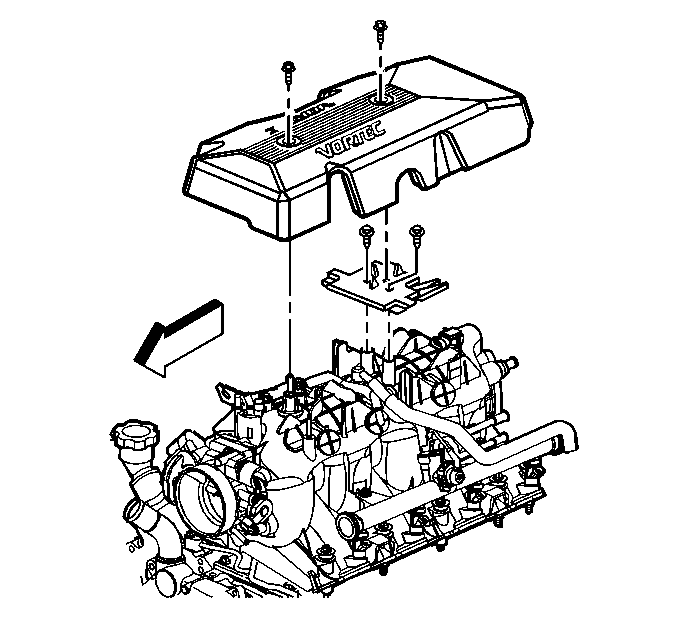
- Remove the engine sight shield. Refer to
Upper Intake Manifold Sight Shield Replacement
.
Caution: In order to avoid possible injury or vehicle damage, always replace
the accelerator control cable with a NEW cable whenever you remove the engine
from the vehicle.
In order to avoid cruise control cable damage, position the cable out
of the way while you remove or install the engine. Do not pry
or lean against the cruise control cable and do not kink the cable. You must
replace a damaged cable.
- Disconnect the accelerator
control cable and the cruise control cable, if equipped, from the throttle
shaft. Refer to
Accelerator Control Cable Replacement
in Engine Controls.
- Position the cables to the side.
- Remove the engine sight shield mounting bracket and the bolts.
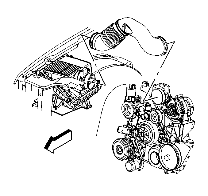
- Remove the air cleaner
duct.
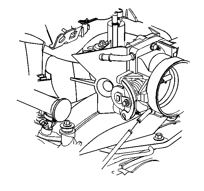
- Remove the inlet coolant
hose from the throttle body.
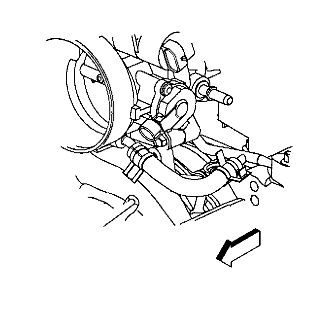
- Remove the vapor vent
tube hose from the throttle body.
- Remove the exhaust gas recirculation (EGR) pipe bracket. Refer
to
Exhaust Gas Recirculation Pipe Replacement
in Engine Controls-4.8L, 5.3L, 6.0L.
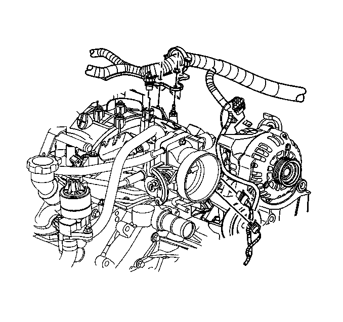
- Open the large electrical
harness retainer, then remove one M6 nut in order to separate the engine harness
from the intake manifold.
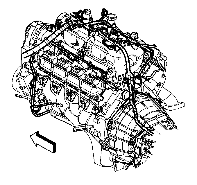
- Disconnect the following
electrical connectors:
| • | Eight fuel injector connectors |
| • | Idle air control (IAC) motor |
| • | Throttle position (TP) sensor |
| • | Evaporative emission (EVAP) canister purge solenoid |
| • | Manifold absolute pressure (MAP) sensor |
- Set the electrical harness aside.
- Disconnect the purge solenoid vent tube from the solenoid by squeezing
the retainer, then release the tube from the solenoid. Refer to
Evaporative Emission Canister Purge Solenoid Valve Replacement
in Engine Controls - 4.8L, 5.3L, 6.0L.
- Disconnect the fuel pipes from the fuel rail. Refer to
Metal Collar Quick Connect Fitting Service
in
Engine Controls - 4.8L, 5.3L, 6.0L.
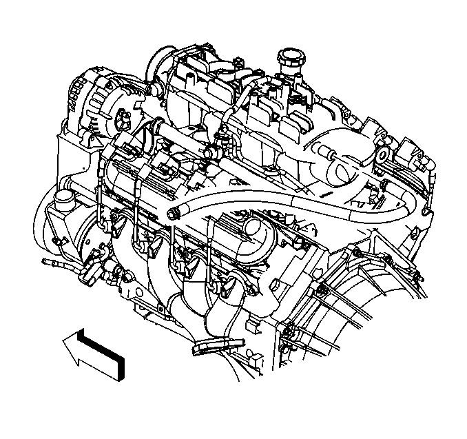
- Remove the vacuum brake
booster hose, if equipped.
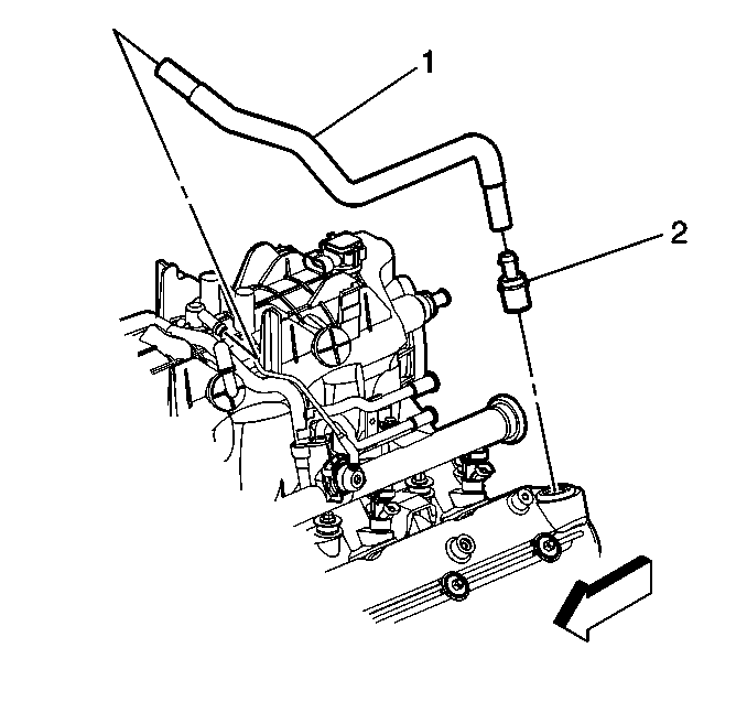
- Remove the positive crankcase
ventilation (PCV) valve (2) and hose (1).
- Remove the intake manifold from the engine. Refer to
Intake Manifold Removal
.
- Clean and inspect the intake manifold and all sealing surfaces.
Refer to
Intake Manifold Cleaning and Inspection
.
Installation Procedure

- Install the intake manifold
to the engine. Refer to
Intake Manifold Installation
.
- Install the vacuum brake booster hose, if equipped.

- Install the PCV valve
(2) and the hose (1).
- Connect the fuel pipes to the fuel rail. Refer to
Metal Collar Quick Connect Fitting Service
in
Engine Controls -- 4.8L, 5.3L, 6.0L.
- Connect the purge solenoid vent tube to the purge solenoid. Refer
to
Evaporative Emission Canister Purge Solenoid Valve Replacement
in Engine Controls -- 4.8L, 5.3L, 6.0L.

Notice: Use the correct fastener in the correct location. Replacement fasteners
must be the correct part number for that application. Fasteners requiring
replacement or fasteners requiring the use of thread locking compound or sealant
are identified in the service procedure. Do not use paints, lubricants, or
corrosion inhibitors on fasteners or fastener joint surfaces unless specified.
These coatings affect fastener torque and joint clamping force and may damage
the fastener. Use the correct tightening sequence and specifications when
installing fasteners in order to avoid damage to parts and systems.
- Install the engine
electrical harness and nut.
Tighten
Tighten the engine wiring harness nut to 10 N·m
(89 lb in).

- Route the harness over
the engine, then install the following connectors.
| • | Eight fuel injector connectors |
| | Caution: In order to avoid possible injury or vehicle damage, always replace
the accelerator control cable with a NEW cable whenever you remove the engine
from the vehicle.
In order to avoid cruise control cable damage, position the cable out
of the way while you remove or install the engine. Do not pry
or lean against the cruise control cable and do not kink the cable. You must
replace a damaged cable.
|
| • | Install the engine sight shield mounting bracket and the bolts. |
- Install the engine sight shield. Refer to
Upper Intake Manifold Sight Shield Replacement
.
- Install the EGR pipe bracket. Refer to
Exhaust Gas Recirculation Pipe Replacement
in Engine Controls-4.8L,
5.3L, 6.0L.

- Install the vapor vent
tube hose to the throttle body.

- Install the coolant hose
to the throttle body.

- Install the air cleaner
duct.
- Fill the engine with coolant. Refer to
Cooling System Draining and Filling
in Engine Cooling.
- Connect the battery negative cable. Refer to
Battery Negative Cable Disconnection and Connection
in Engine Electrical.


