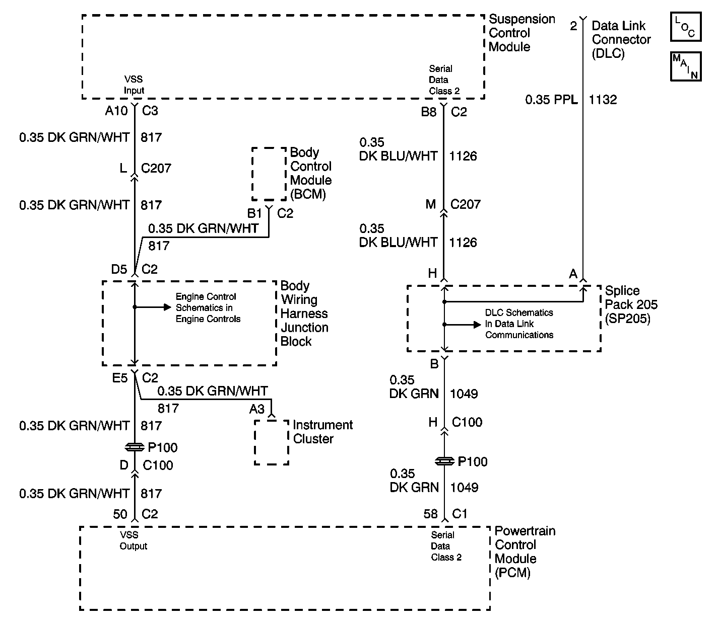
DTC C0000 Vehicle Speed Information Circuit Malfunction W/RTD

Circuit Description
The suspension control module receives a vehicle speed signal input from the powertrain control module via the vehicle speed signal circuit and also receives vehicle speed data over the serial data class 2 circuit. Once vehicle speed has been detected, the suspension control module compares the two inputs for accuracy.
Conditions for Running the DTC
Continuously after vehicle speed has been detected from one or both inputs.
Conditions for Setting the DTC
Class 2 vehicle speed is greater than 32 kph (20 mph) and the calculated speed input (hard wire) is less than 5 kph (3 mph) contentiously for 10 seconds.
Action Taken When the DTC Sets
| • | Disable EVO outputs. |
| • | DTC C0000 will be stored in memory. |
Conditions for Clearing the MIL/DTC
| • | The suspension control module detects a vehicle speed signal from the PCM of greater than 20 MPH. |
| • | A history DTC will clear after not seeing the malfunction for 100 consecutive ignition cycles. |
| • | Using a scan tool. |
Test Description
The number(s) below refer to the step number(s) on the diagnostic table.
-
Tests whether the condition is module, system, or condition related.
-
Tests whether the condition has been corrected or identified as specified in the supporting text.
-
Test for an open or short in the vehicle speed signal circuit of the suspension control module.
Step | Action | Value(s) | Yes | No |
|---|---|---|---|---|
1 | Did you perform the RTD Diagnostic System Check? | -- | Go to Step 2 | Go to Diagnostic System Check |
2 |
Does the scan tool indicate that DTC C0000 is current? | -- | Go to Step 4 | Go to Step 3 |
Since most occurrences of this DTC are caused by a short or open vehicle speed signal circuit to the suspension control module, review the RTD System operation or, with the customer to verify the conditions under which the DTC set. Did vehicle operation cause this DTC to set? | -- | Go to Step 6 | Go to Step 4 | |
IMPORTANT: Do not cycle the ignition. Does the DTC reset? | -- | Go to Step 5 | System OK | |
Test the vehicle speed signal circuit of the suspension control module for a short to ground, short to voltage and an open. Refer to Circuit Testing and Wiring Repairs in Wiring Systems. Did you find and correct the condition? | -- | System OK | Go to Step 7 | |
6 |
Does the DTC reset? | -- | Go to Step 7 | System OK |
7 | Replace the Suspension Control Module. Refer to Electronic Suspension Control Module Replacement . Did you complete the replacement? | -- | System OK | -- |
DTC C0000 Vehicle Speed Information Circuit Malfunction W/O RTD
For a full page schematic, refer to Steering Assist Schematics
Circuit Description
The body control module receives a vehicle speed signal input from the powertrain control module via the vehicle speed signal circuit and also receives vehicle speed data over the serial data class 2 circuit. Once vehicle speed has been detected, the body control module compares the two inputs for accuracy.
Conditions for Running the DTC
Continuously after vehicle speed has been detected from one or both inputs.
Conditions for Setting the DTC
Class 2 vehicle speed is greater than 20 MPH and the calculated speed input (hard wire) is less than 3 MPH continuosly for 10 seconds.
Action Taken When the DTC Sets
| • | Disable EVO outputs. |
| • | DTC C0000 will be stored in memory. |
Conditions for Clearing the DTC
| • | The body control module detects a vehicle speed signal from the PCM of greater than 20 MPH. |
| • | A history DTC will clear after not seeing the malfunction for 100 consecutive ignition cycles. |
| • | Using a scan tool. |
Diagnostic Aids
| • | Perform a visual inspection for loose or poor connections at all related components. |
| • | Refer to Testing for Intermittent Conditions and Poor Connections in Wiring Systems. |
Test Description
The number(s) below refer to the step number(s) on the diagnostic table.
-
Tests whether the condition is module, system, or condition related.
-
Tests whether the condition has been corrected or identified as specified in the supporting text.
-
Test for an open or short in the vehicle speed signal circuit of the body control module.
Step | Action | Yes | No |
|---|---|---|---|
1 | Did you perform the Variable Effort Steering Diagnostic System Check? | Go to Step 2 | Go to Diagnostic System Check |
2 |
Does the scan tool indicate that DTC C0000 is current? | Go to Step 4 | Go to Step 3 |
Since most occurrences of this DTC are caused by a short or open vehicle speed signal circuit of the body control module, review the variable effort steering system operation or, verify with the customer the conditions under which the DTC set. Did vehicle operation cause this DTC to set? | Go to Step 6 | Go to Step 4 | |
IMPORTANT: Do not cycle the ignition. Does the DTC reset? | Go to Step 5 | System OK | |
Test the vehicle speed signal circuit of the body control module for a short to ground, short to voltage or an open. Did you find and correct the condition? | System OK | Go to Step 7 | |
6 |
Does the DTC reset? | Go to Step 7 | System OK |
7 |
Did you complete the replacement? | System OK | -- |
