For 1990-2009 cars only
Steering Wheel Position Sensor or Steering Shaft Lower Bearing Replacement Centering Not Required
Tools Required
J 42640 Steering Column Anti Rotation Pin
Removal Procedure
- Set the front wheels in the straight-ahead position.
- Install J 42640 or set the steering wheel in the LOCKED position.
- Disconnect the negative battery cable.
- Disable the SIR. Refer to Disabling the SIR System in SIR.
- Make an alignment mark on the upper and lower steering shafts where they connect before removal.
- Remove the nut and the bolt from the upper to the lower steering shaft connection.
- Remove the steering wheel position sensor connector by using a suitable tool in order to pull the connector down around the right side of the steering column for accessibility.
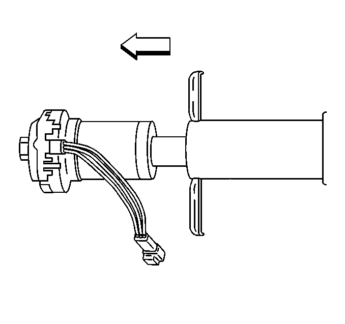
- Remove the steering wheel position sensor and adapter and bearing assembly from the steering column jacket by pulling the assembly straight out.
- Remove the steering wheel position sensor from the clips in the adapter and bearing assembly.
Caution: Refer to SIR Caution in the Preface section.
Important: You MUST make an alignment mark on the upper to lower steering shaft connection. You will need the alignment marks for installation.
Slide the lower shaft down.

Important: Do not apply force to the steering wheel position sensor and the adapter and bearing assembly in a sideways direction.
The steering wheel position sensor does NOT require centering.Installation Procedure
- Install the steering wheel position sensor into the adapter and bearing assembly.
- Verify the following before installing the steering wheel position sensor:
- Install the adapter and bearing assembly into the steering column jacket.
- Connect the steering wheel position sensor connector.
- Align the marks on the upper and lower steering shafts, where they connect, that you made during the removal procedure.
- Install the bolt and the nut to the upper end of the shaft.
- Connect the negative battery cable.
- Enable the SIR system. Refer to Enabling the SIR System in SIR.
Important: A new steering wheel position sensor does NOT come with a pin installed.
The steering wheel position sensor does NOT require centering.| • | The front wheels are in the straight-ahead position. |
| • | That J 42640 is installed or the steering wheel is in the LOCKED position. |
| 3.1. | Align the notches on the adapter and bearing assembly and the steering column jacket. |
| Important: Do not apply force to the steering wheel position sensor and the adapter and bearing assembly in a sideways direction. |
| 3.2. | Seat the adapter and bearing assembly into the steering column jacket. |
Notice: Refer to Fastener Notice in the Preface section.
Tighten
Tighten the nut to 62 N·m (46 lb ft).
