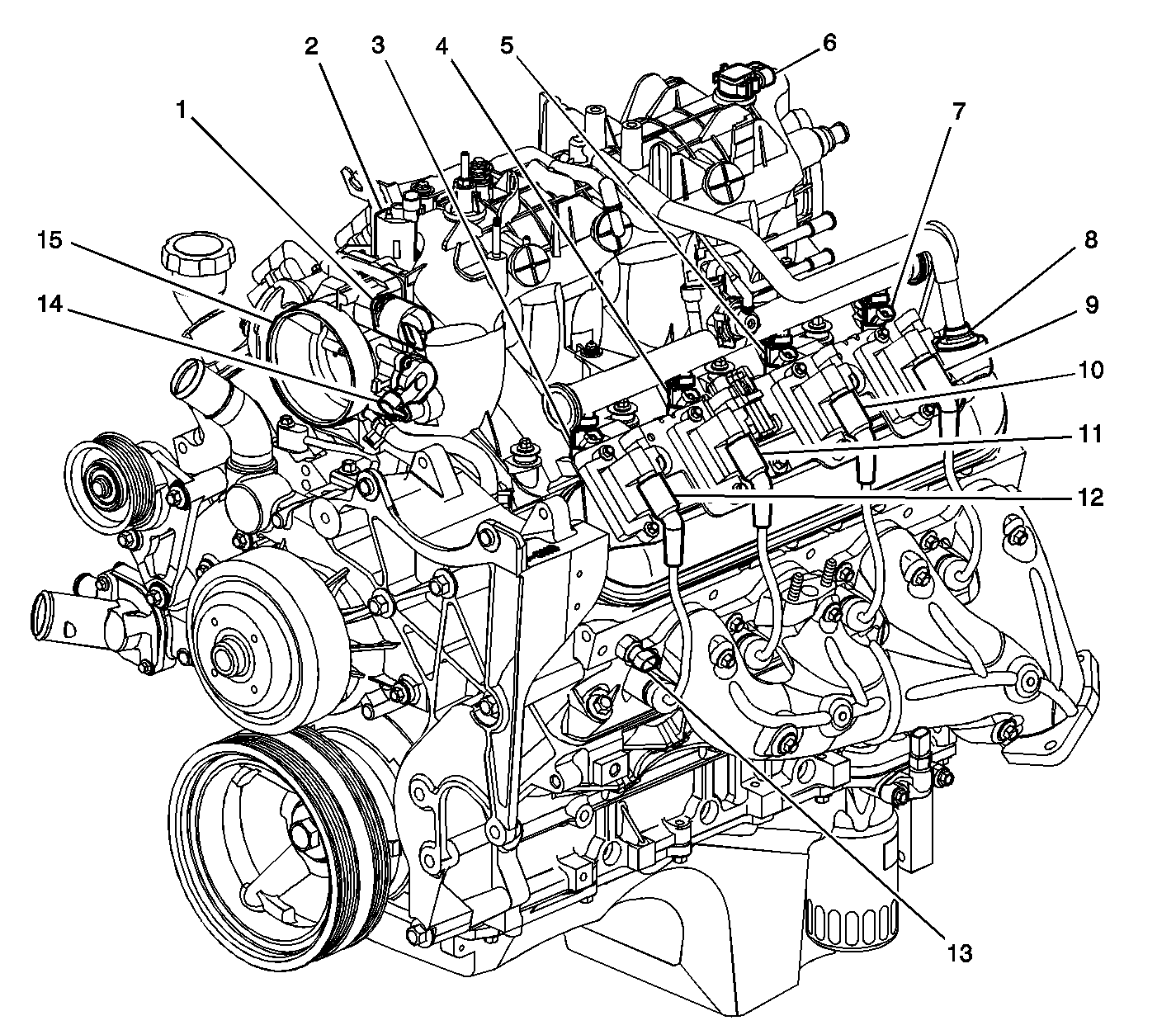
| Figure 1: |
Full Engine View Left Side
|
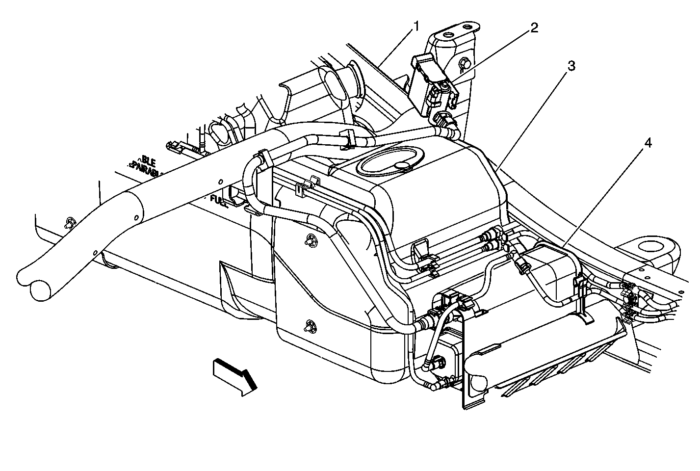
| Figure 2: |
Evaporative Emission (EVAP) Canister Vent Solenoid
|
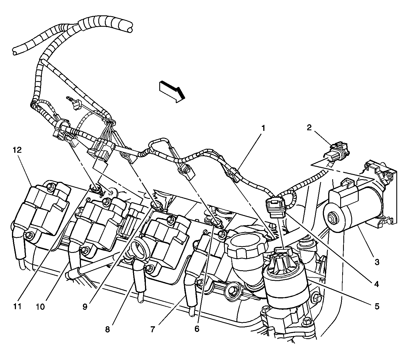
| Figure 3: |
EGR, TAC Motor and Ignition Coils 2, 4, 6, 8
|
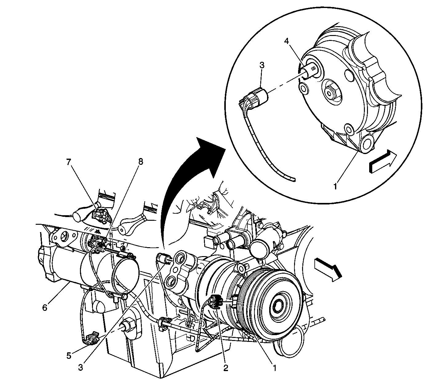
| Figure 4: |
A/C Compressor Clutch, Oil Level Switch, CKP Sensor and Starter
|
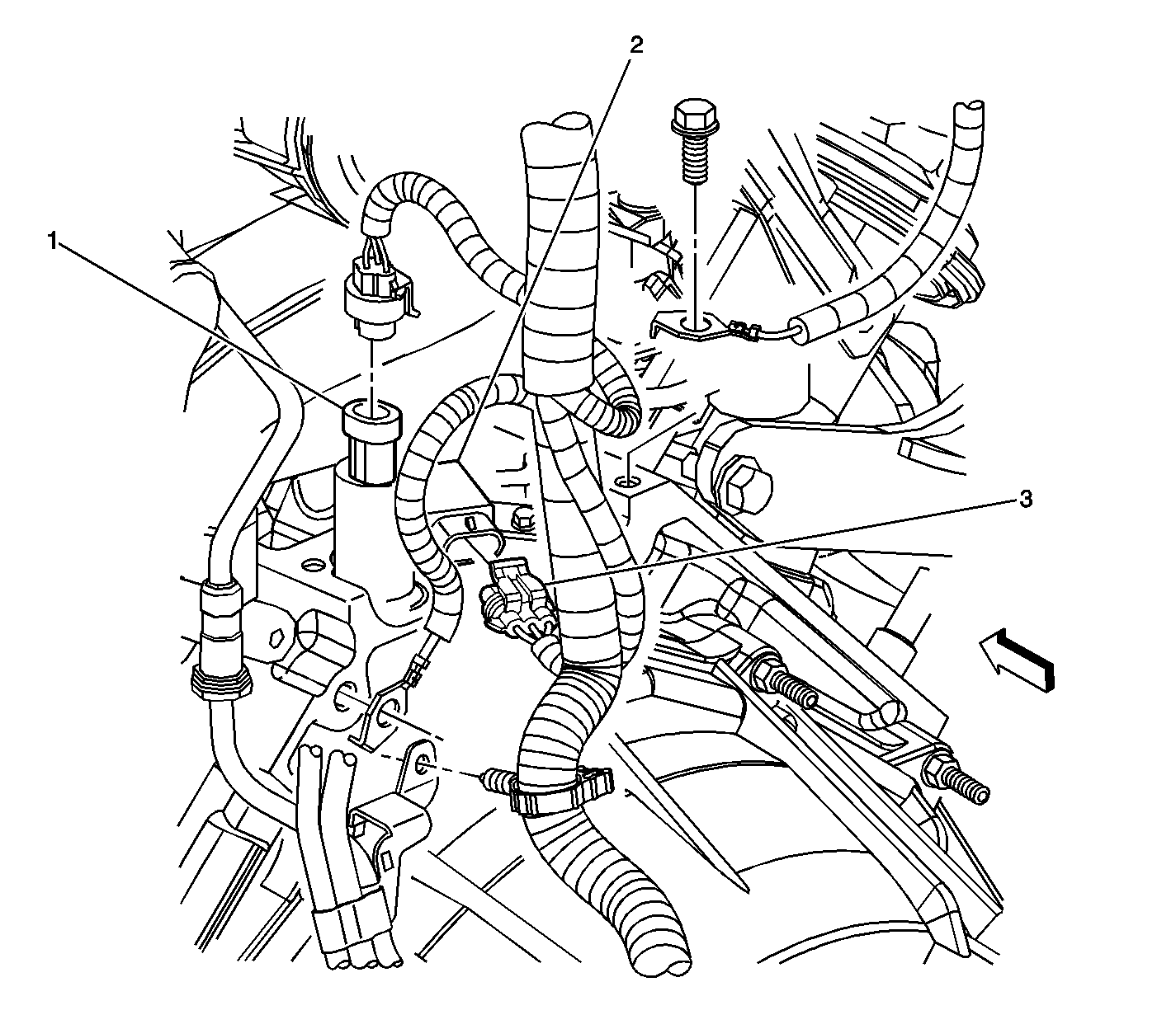
| Figure 5: |
Engine Oil Pressure (EOP) Sensor and CMP Sensor
|
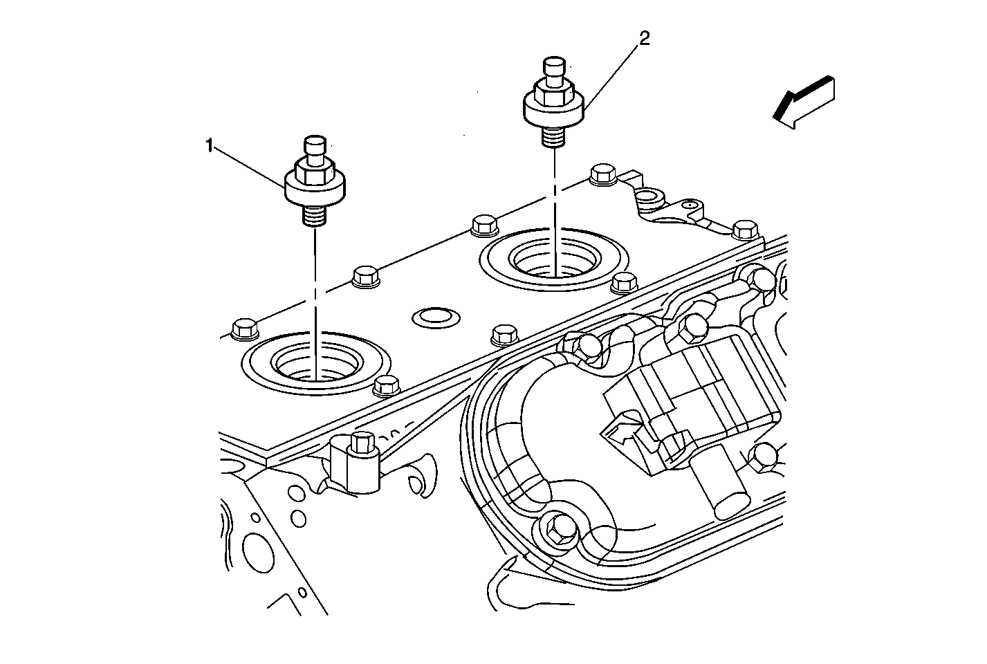
| Figure 6: |
Knock Sensors
|
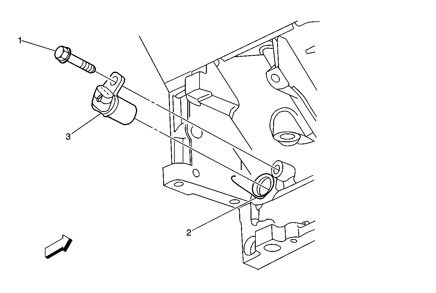
| Figure 7: |
Lower RR of the Engine Components (4.8L/5.3L/6.0L)
|
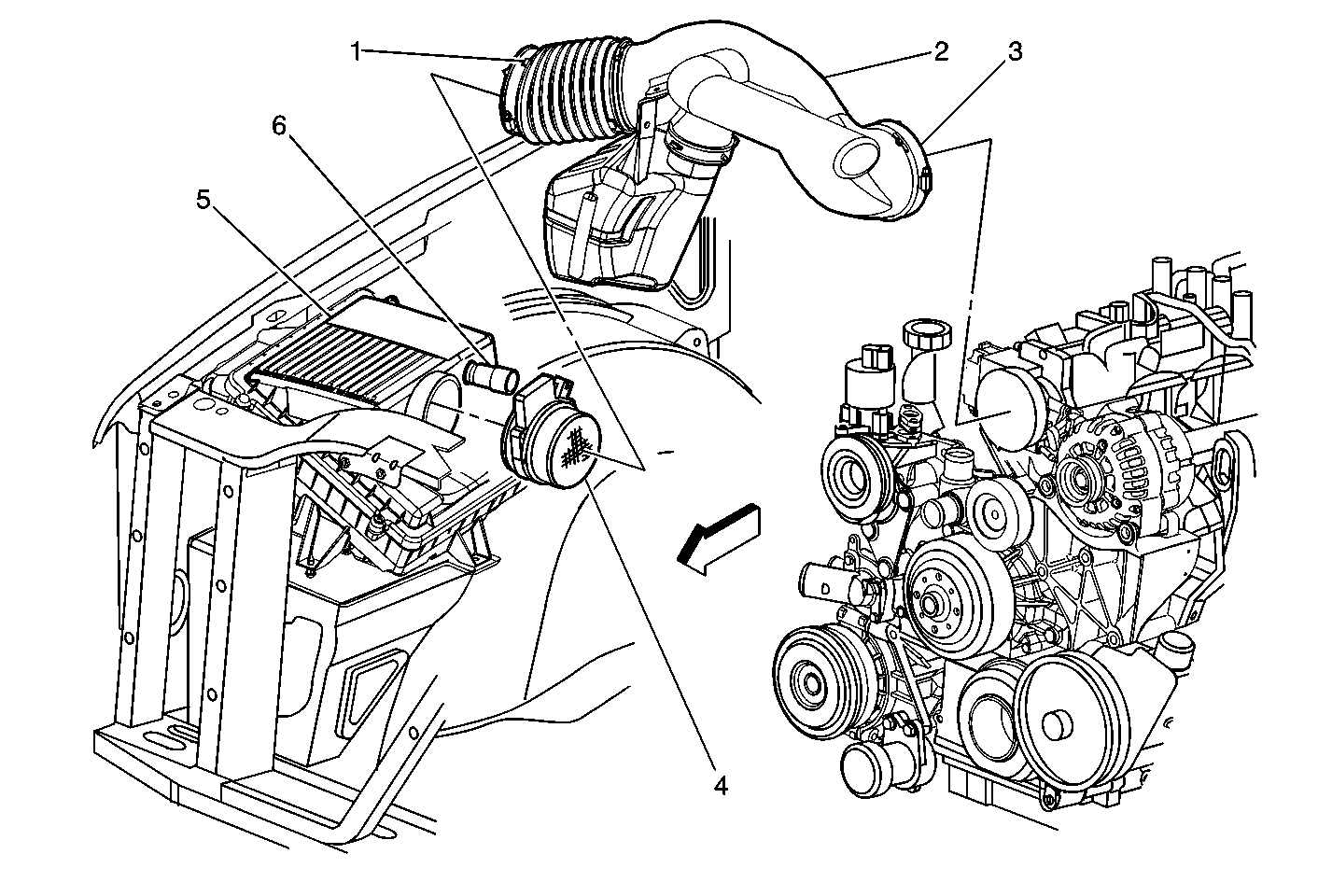
| Figure 8: |
Air Induction Components
|
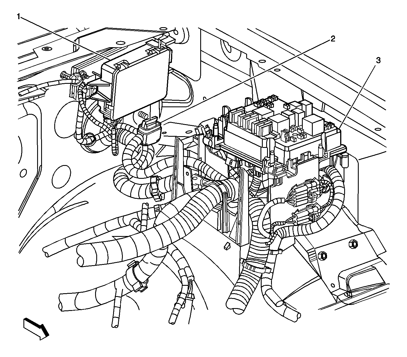
| Figure 9: |
Throttle Actuator Control (TAC) Module
|
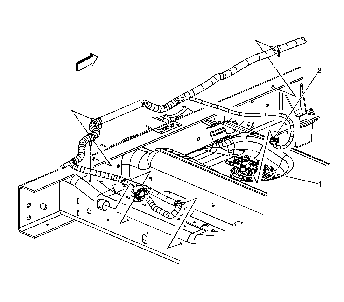
| Figure 10: |
Fuel Pump and Sender Assembly - Secondary - w/Dual Tanks
|
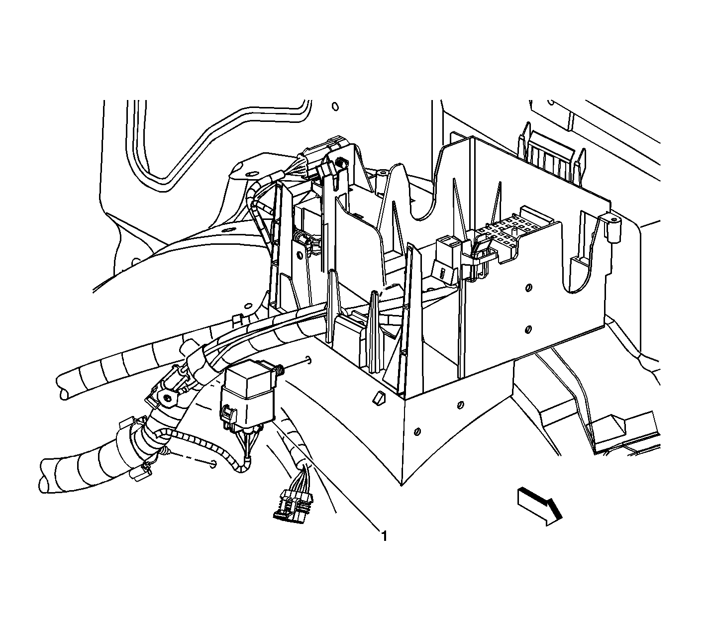
| Figure 11: |
Fuel Pump Relay - Secondary - w/Dual Tanks
|
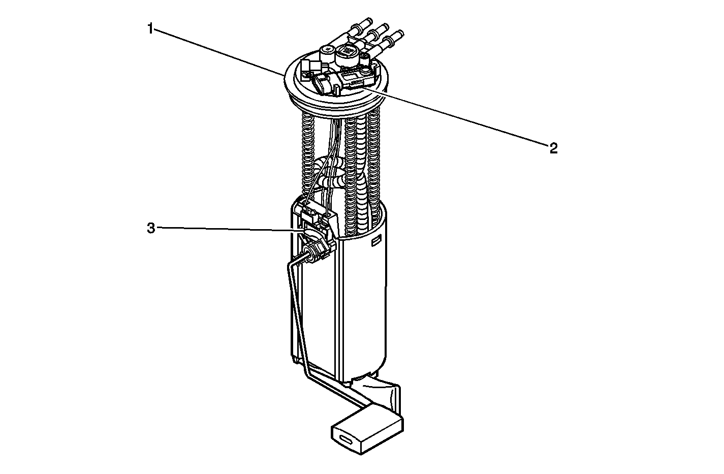
| Figure 12: |
Fuel Pump and Sender Assembly Components
|
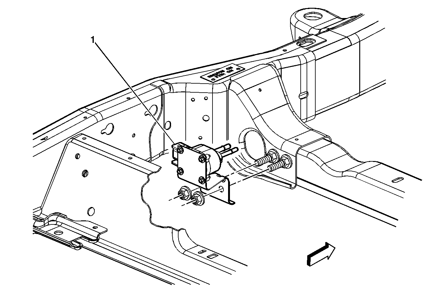
| Figure 13: |
Fuel Composition Sensor - w/L59 Only
|
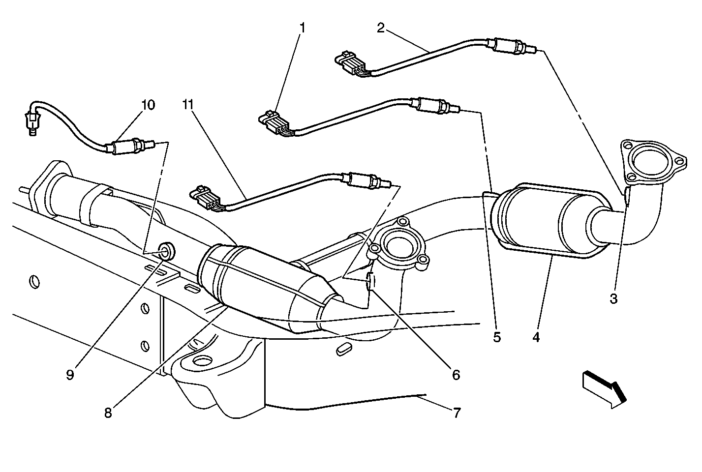
| Figure 14: |
Heated Oxygen Sensor (HO2S) 4.8L and 5.3L
|
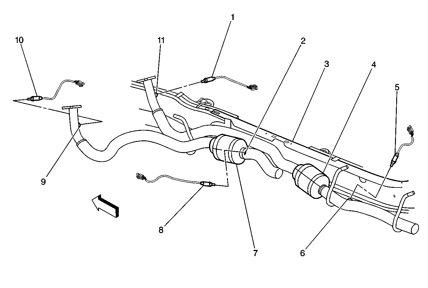
| Figure 15: |
Heated Oxygen Sensors (HO2S) 6.0L
|
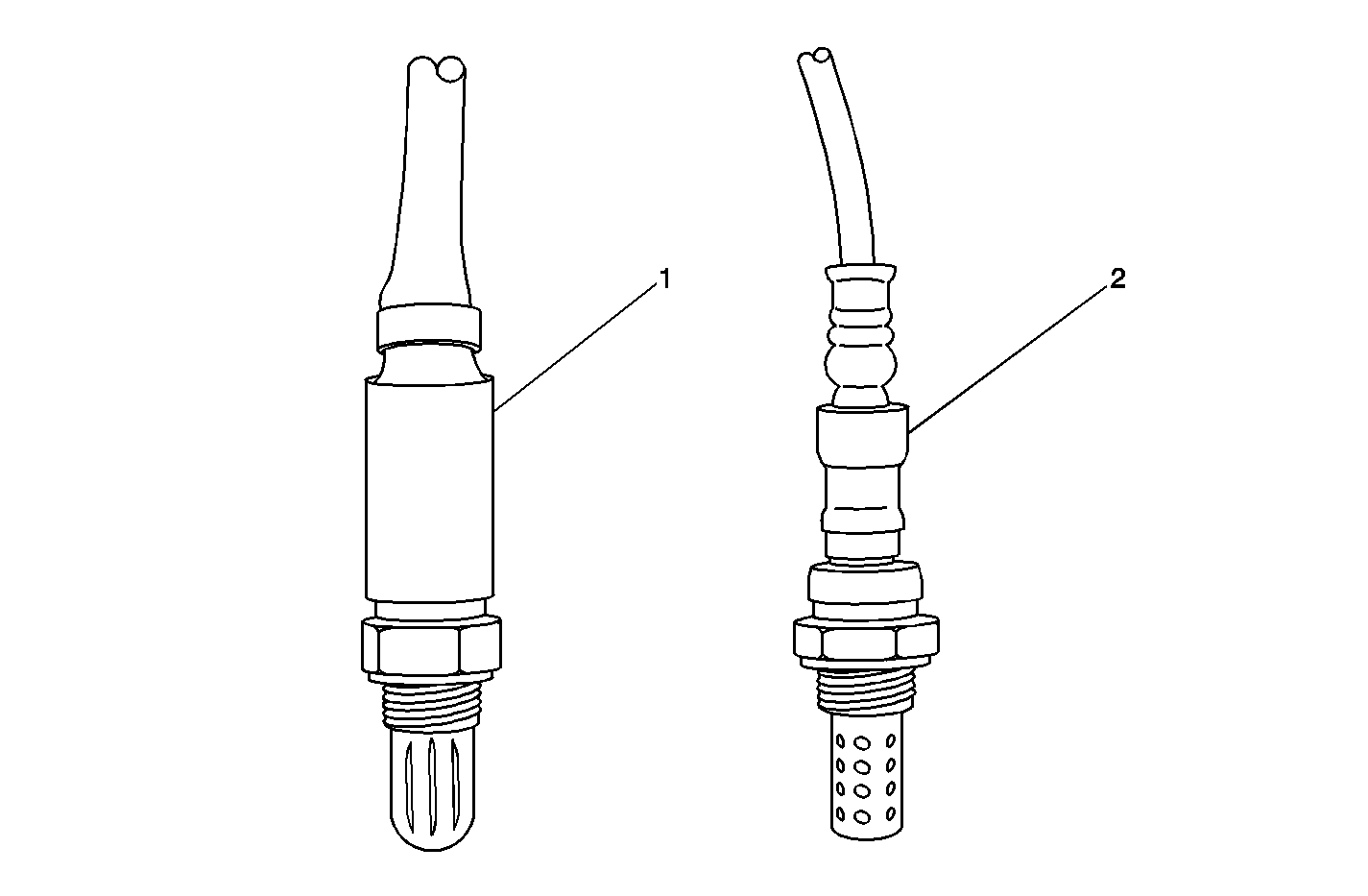
| Figure 16: |
Heated Oxygen Sensor Identification
|
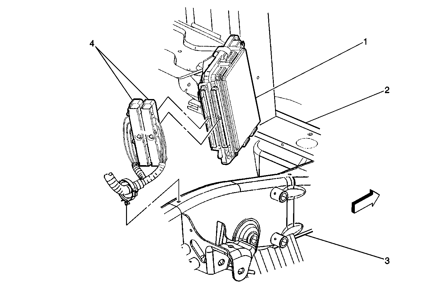
| Figure 17: |
PCM Location
|
| Figure 18: |
Throttle Actuator Control (TAC) Module

|
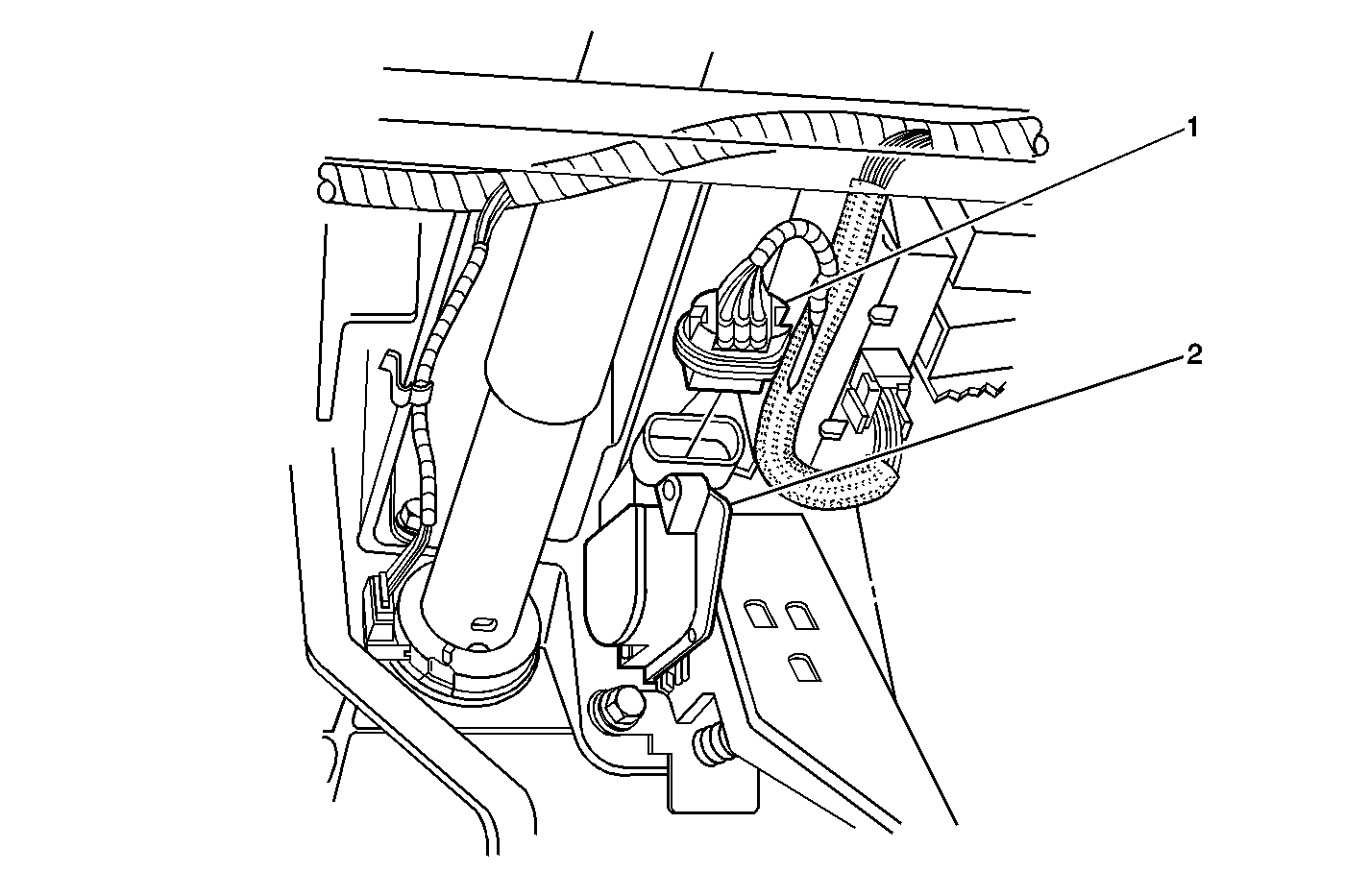
| Figure 19: |
Accelerator Pedal Position (APP) Sensor Connector
|


