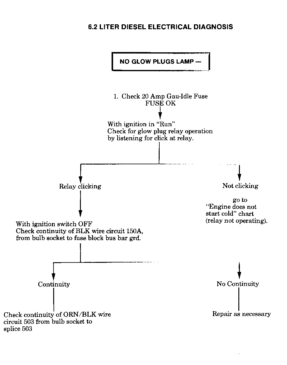
DIESEL GLOW PLUG SYSTEM/6.2L DIAGNOSIS INFORMATION/NO START

The following should be used in conjunction with the service manual for diagnosing the glow plug system:
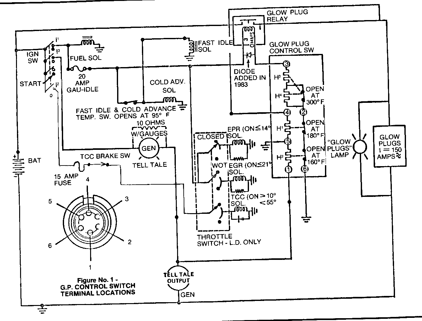
GLOW PLUG CONTROLLER CONNECTOR CIRCUIT CHECKS
Pin 1: (Brown Wire) should have continuity (0 ohms resistance) to the brown wire at the alternator with the engine off or alternator voltage with the engine running. If there is battery voltage at this pin with the ignition key off, the alternator has failed a diode (see below).
Pin 2: There is no connection to this pin on 1982 vehicles. On 1983 vehicles, there may be a white tube or a wire to this pin, it is only to seal the position in the connector. It is hooked to the wiring harness. DO NOT GROUND THIS PIN FOR ANY REASON, IT WILL PROHIBIT NORMAL OPERATION OF THE CONTROLLER AND CAN DAMAGE GLOW PLUGS.
Pin 3: (Blue Wire) should have battery voltage with the vehicle ignition key on.
Pin 4: (Orange Wire) should have continuity (0 ohms resistance) to the double red wire terminal on the glow plug relay.
Pin 5: (Black wire) should have continuity (0 ohms resistance) to Pin 6 (Black Wire) and to ground.
Pin 6: (Black Wire) same as Pin 5.
Complaints of a "no-start - due to no glow plugs heating" have been received where the no-start problem was a result of a failed delcotron positive diode.
When the diode fails in the delcotron, battery voltage can be supplied to the glow plug controller with the key off and the engine stopped. This battery voltage is normally supplied to Pin #1 in the glow plug controller from the delcotron after the engine starts. This voltage, in effect, tells the controller that the engine has started and shuts off the glow plug heating cycle.
When a "no glow plug heating" problem is received, a quick check should be made to see if a diode failure is the cause.
Follow this procedure:
1. With the key off and the engine stopped, check for voltage in the brown wire that goes from the delcotron to the glow plug controller.
2. If a voltage is present, disconnect the wire from the delcotron. Again, check the voltage in the brown wire. There should be none. (If the key is "on", a low voltage, approximately 3 volts, will be present in a properly operating system.)
Wait for a minimum of fifteen (15) minutes, or sufficient time for the controller to cool off.
4. Turn the key on. If the glow plugs heat, the problem was with the delcotron.
NOTICE: The only time battery voltage should be present in the brown wire is when the engine is running. With the key on, and the engine not running, a low voltage (approximately 3 volts) will be present in the brown wire. This is normal.
GLOW PLUG CONTROLLER CHECK FOR PROPER FUNCTION
Engine Cold, Ignition Switch Off
1. First connect a VOM between the negative side (blue wire) of the power relay coil and ground.
CAUTION:
Do not short the positive terminal to any metal object.
2. Monitor the VOM when the ignition switch is turned on. Turn the ignition switch on.
3. The VOM should read about 2 VDC for approximately 4 to 10 seconds, depending on the engine coolant temperature.
Notice: if the engine is hot, you may get a continuous voltage reading of about 12 VDC (the battery voltage).
4. The VOM will then repeat an on-off cycle, about 12 VDC then 2 VDC.
NOTICE: The power relay should also be heard turning on and off.
5. If this occurs, the controller is functioning properly. Remove the positive lead of the VOM from the power relay coil and connect to the relay output.
6. With the ignition switch still on, the VOM should continue to repeat the on-off cycle of 3 above.
7. If this is occurring, the proper voltage is being applied to the wiring harness connected to the glow plugs.
ASSEMBLY PLANT CHECKOUT OF 1983 "G" VAN 6.2L DIESEL GLOW PLUG SYSTEM
Normal Operation
With cold engine (below approximately 100 DEG F), and good batteries (green eye visible):
1. Ignition switch on.
2. Glow plugs light "on" for 10 seconds maximum (engine below 20 DEG F), "on" for 7 seconds maximum with engine at room temperature.
3. Glow plug light then cycles on-off.
4. Start engine.
5. Glow plug light continues to cycle on-off for up to one (1) minute with cold engine (below 20 DEG F), less time if engine is warmer.
6. Light remains off as long as engine is running.
Visual Check
If glow plug light does not operate as above, check the following:
1. Check connections on glow plug lamp jumer harness in I.P. area.
a. "Ground" at bus bar ground terminal.
b. Fuse block.
c. Two 92) wire connections to bulkhead connector (ORN/DBL) BLK. stripe and YEL/DBL. BLK. stripe)
2. Check connections in engine compartment.
a. "Ground" at stud - power steering brace.
b. Glow plug relay 2-way connector and connections at studs.
c. Glow plug controller.
d. 2-Way connector on delcotron.
If all connections are intact, but glow plug system is not operating as stated, proceed with normal diagnostic procedure. DO NOT BYPASS OR MANUALLY OPERATE WITH GLOW PLUG RELAY.
GLOW PLUG
THERMAL CONTROLLER CHECK
With connector removed from controller the controller heater circuits may be checked using a high impedance ohmeter. However, this check will not determine shorted switches within the controller.
Pin 3 - Pin 2 .40 to .75 Ohms Pin 5 - Pin 1 130 Ohms - 10% Pin 4 - Pin 5 27 Ohms - 3 Ohms Pin 2 - Pin 6 Continuity ("O" ohms)
GLOW PLUGS LAMP
CYCLES ON AND OFF
WARM ENGINE
This condition can be caused by an open circult in 25 circuit from gen telltale output to pin 1 of the controller, or by generator output failure - to check generator operation, see Section 6D of manual.


General Motors bulletins are intended for use by professional technicians, not a "do-it-yourselfer". They are written to inform those technicians of conditions that may occur on some vehicles, or to provide information that could assist in the proper service of a vehicle. Properly trained technicians have the equipment, tools, safety instructions and know-how to do a job properly and safely. If a condition is described, do not assume that the bulletin applies to your vehicle, or that your vehicle will have that condition. See a General Motors dealer servicing your brand of General Motors vehicle for information on whether your vehicle may benefit from the information.
