Removal Procedure
- Disconnect the negative battery cable.
- Relieve the fuel system pressure. Refer to the Fuel Pressure Relief Procedure .
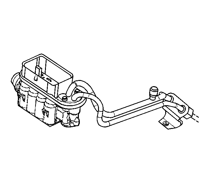
- Disconnect the fuel lines at rear of the intake manifold.
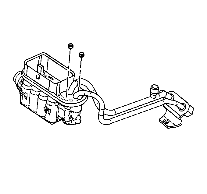
- Remove the nuts
- Remove the retainer
- Disconnect the injector fuel inlet pipe and the outlet pipe.
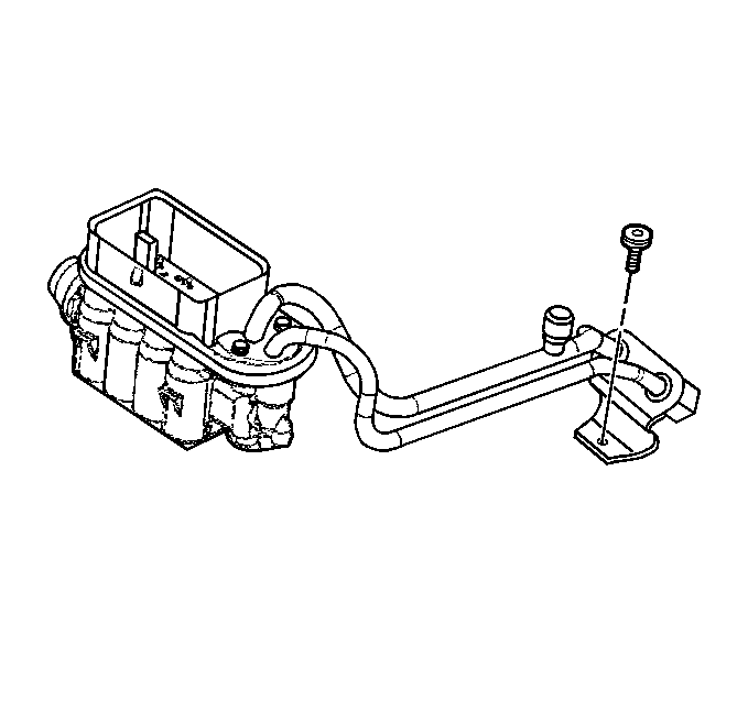
- Remove the rear fuel line bracket.
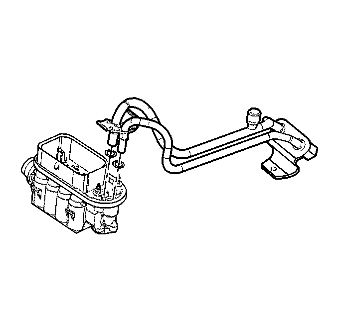
- Pull straight up on fuel pipe to remove fuel pipes from injector assembly.
- Remove the O-ring seals from both ends of the fuel feed and return pipes and discard.
Caution: Unless directed otherwise, the ignition and start switch must be in the OFF or LOCK position, and all electrical loads must be OFF before servicing any electrical component. Disconnect the negative battery cable to prevent an electrical spark should a tool or equipment come in contact with an exposed electrical terminal. Failure to follow these precautions may result in personal injury and/or damage to the vehicle or its components.


Important: Check the injector assembly to insure the O-rings have been removed.
Installation Procedure
Caution: In order to reduce the risk of fire and personal injury, before connecting fuel pipe fittings, always apply a few drops of clean engine oil to the male pipe ends.
This will ensure proper reconnection and prevent a possible fuel leak. During normal operation, the O-rings located in the female connector will swell and may prevent proper reconnection if not lubricated.Important: Remember to install the new O-rings into the inlet and outlet of the fuel injector assembly, using the seal retainer tool.
- Apply a few drops of clean engine oil to the male tube ends.
- Connect the fuel feed and return pipes to fuel assembly.
- Install the fuel pipe retainer and attaching nuts. Once installed, pull on both ends of each connection to make sure they are secure.
- Install the rear fuel pipe clip retaining bolt.
- Install the new O-ring seals on the engine fuel feed and return pipes.
- Connect the fuel feed and return lines to the engine fuel pipes.
- Tighten the fuel filler cap.
- Connect the negative battery cable.
- Check for fuel leaks.


Notice: Use the correct fastener in the correct location. Replacement fasteners must be the correct part number for that application. Fasteners requiring replacement or fasteners requiring the use of thread locking compound or sealant are identified in the service procedure. Do not use paints, lubricants, or corrosion inhibitors on fasteners or fastener joint surfaces unless specified. These coatings affect fastener torque and joint clamping force and may damage the fastener. Use the correct tightening sequence and specifications when installing fasteners in order to avoid damage to parts and systems.

Tighten
| • | Tighten the rear fuel line bracket bolt to 6.0 N·m (53 lb in). |
| • | Tighten the fuel pipe retainer nuts to 3.0 N·m (27 lb in). |

Tighten
Tighten the fuel pipe nuts to 30N·m (22 lb ft).
| 9.1. | Turn the ignition switch to the ON position for 2 seconds. |
| 9.2. | Turn the ignition switch to the OFF position for 10 seconds. |
| 9.3. | Again, turn the ignition switch to the ON position. |
| 9.4. | Check for fuel leaks. |
