Refer to Emission Hose Routing Diagram
Circuit Description
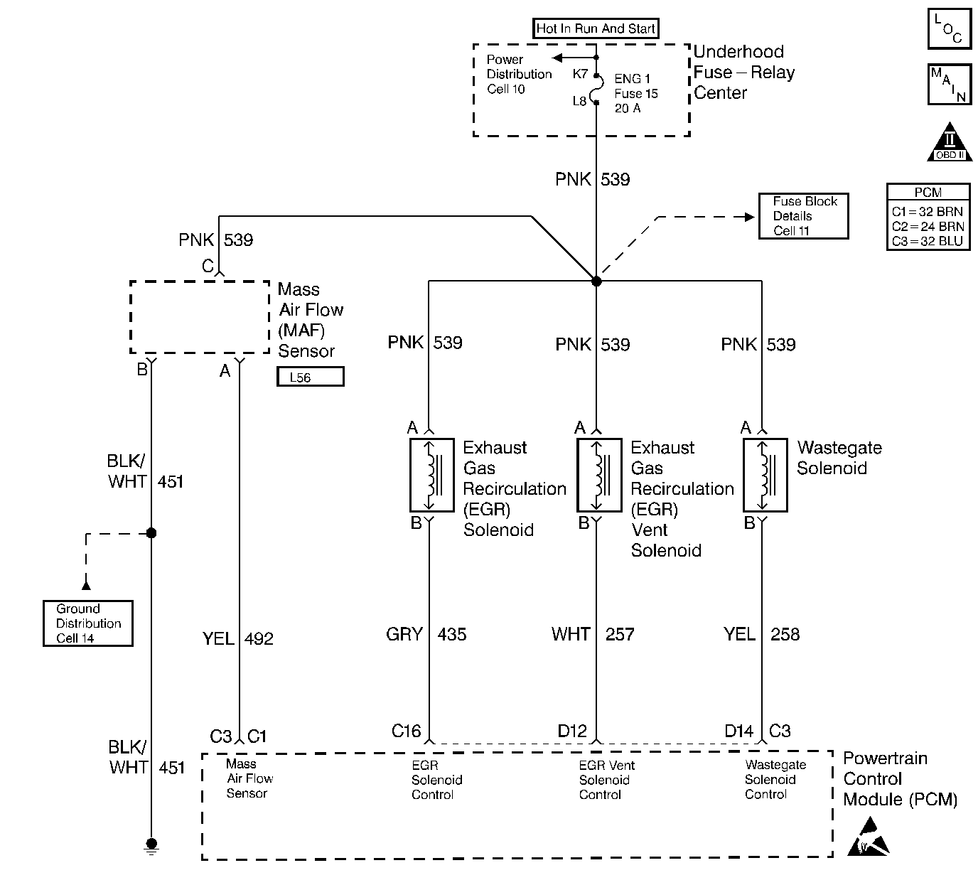
The mass air flow (MAF) sensor measures the amount of air entering the engine during a given time. The PCM uses the mass air flow information to monitor EGR flow rates. A large quantity of air entering the engine indicates an acceleration, high load situation or no EGR flow, while a small quantity of air indicates deceleration, idle or full EGR situations.
The PCM will monitor MAF and EGR pressures at different ranges to determine correct EGR flow rates.
Conditions for Running the DTC
| • | DTCs P0405, P0406, P0102 and P0103 not set. |
| • | Engine at operating temperature. |
| • | IAT greater than or equal to 20°C (68°F) and less than or equal to 95°C (203°F). |
Conditions for Setting the DTC
IAT greater than or equal to 20°C (68°F) and less than or equal to 95°C (203°F).
Action Taken When the DTC Sets
| • | The PCM illuminates the malfunction indicator lamp (MIL) on the second consecutive drive trip the diagnostic runs and fails. |
| • | The PCM records the operating conditions at the time the diagnostic fails. The first time the diagnostic fails, the Failure Records store this information. If the diagnostic reports a failure on the second consecutive drive trip, the Freeze Frame records the operating conditions at the time of failure and updates the Failure Records. |
Conditions for Clearing the MIL/DTC
| • | The PCM will turn the MIL off after three consecutive trips without a fault condition. |
| • | A History DTC clears after forty consecutive warm-up cycles, if this or any other emission related diagnostic does not report any failures |
| • | The use of a scan tool. |
Diagnostic Aids
A vacuum leak will cause a DTC P1409. Carefully check all vacuum lines and components connected to the hoses for leaks or deformities. Check the vacuum source to the EGR solenoid assembly. Also check for a small leak in the EGR valve, and proper vacuum line routing. Refer to Emission Hose Routing Diagram . Vacuum line ends can be trimmed to ensure a tight fit if length permits.
To run the diagnostic test the engine must be at operating temperature with the vehicle in drive at idle for approximately 1 minute. Then, with the vehicle in park, hold engine rpm steady between 1500 and 2100 rpm for 30 seconds. If the diagnostic test fails to run, the vehicle must be driven.
The Adaptive Learn Matrix (ALM) is used to adjust the EGR vacuum control based on mass air flow (MAF). The ALM may change as a result of back pressure increases over the life of the vehicle or other engine system variations. The ALM is made up of sixteen cells (numbered from zero to fifteen) in which each cell covers a range of engine speed (RPM) and load (mm3).
Test Description
Number(s) below refer to the step number(s) on the Diagnostic Table.
-
This step checks for a vacuum source to the EGR valve.
-
This step checks for a malfunctioning EGR vent solenoid.
-
This step checks for a good vacuum source.
Step | Action | Value(s) | Yes | No | ||||
|---|---|---|---|---|---|---|---|---|
1 |
Important: Before clearing any DTCs, use the scan tool Capture Info to save freeze frame and failure records for reference, as the Scan tool loses data when using the Clear Info function. Was the Powertrain On-Board Diagnostic (OBD) System Check performed? | -- | ||||||
Is the vacuum greater than or equal to the specified value? | 15 in. Hg | |||||||
Is the vacuum greater than or equal to the specified value? | 15 in. Hg | |||||||
4 |
Does the EGR valve hold vacuum? | -- | ||||||
Is the vacuum greater than or equal to the specified value? | 15 in. Hg | |||||||
6 | DTC is intermittent. If no additional DTCs are stored, refer to Diagnostic Aids. If additional DTCs were stored refer to those table(s). Are any additional DTC(s) stored? | -- | Go to the Applicable DTC Table | Go to Diagnostic Aids | ||||
7 | Repair one of the following:
Is the action complete? | -- | -- | |||||
8 |
Was a problem found? | -- | ||||||
9 | Replace the vacuum pump. Is the action complete? | -- | -- | |||||
10 | Repair one of the following:
Is action complete? | -- | -- | |||||
11 | Replace the EGR valve. Refer to Exhaust Gas Recirculation Valve Replacement . Is the action complete? | -- | -- | |||||
12 |
Important: After the Repairs, the EGR ALM cells must be reset (under special functions in scan tool). Are the EGR ALM cells reset? | -- | -- | |||||
13 |
Does the Scan Tool indicate the diagnostic Passed? | -- | ||||||
14 | Does the Scan tool display any additional undiagnosed DTCs? | -- | Go to the Applicable DTC Table | System OK |
