SMU - Revised Wheel Bearing Adjustment Procedure

| Subject: | Revised Wheel Bearing Adjustment Procedure |
| Models: | 2001-2002 Chevrolet and GMC C/K and G-Van Models |
| with 10.5 and 11.5 Inch Axles |
This bulletin is being issued to revise the Wheel Bearing Adjustment procedure in the Rear Drive Axle sub-section of the Service Manual. Please replace the current information in the Service Manual with the following information.
The following information has been updated within Service Information (SI). If you are using a paper version of this Service Manual, please make a reference to this bulletin on the affected page.
Wheel Bearing Adjustment
Preliminary Inspection
Important: Ensure the brakes are fully released and do not drag.
Pull or push the tire at the top back and forth in order to test the wheel bearing play.
| • | Use a pry bar under the tire as an alternative. |
| • | If the wheel bearing adjustment is correct, the movement will be barely noticeable. |
| • | If the movement is excessive, adjust the bearings. |
Adjustment Procedure
Tools Required
J 2222-C Wheel Bearing Nut Wrench
- Raise the vehicle. Refer to Lifting and Jacking the Vehicle in General Information.
- Remove the axle shaft. Refer to Rear Axle Shaft and/or Gasket Replacement.
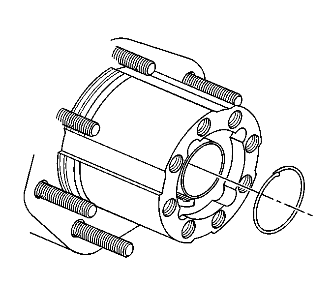
- Remove the hub adjuster nut retaining ring.
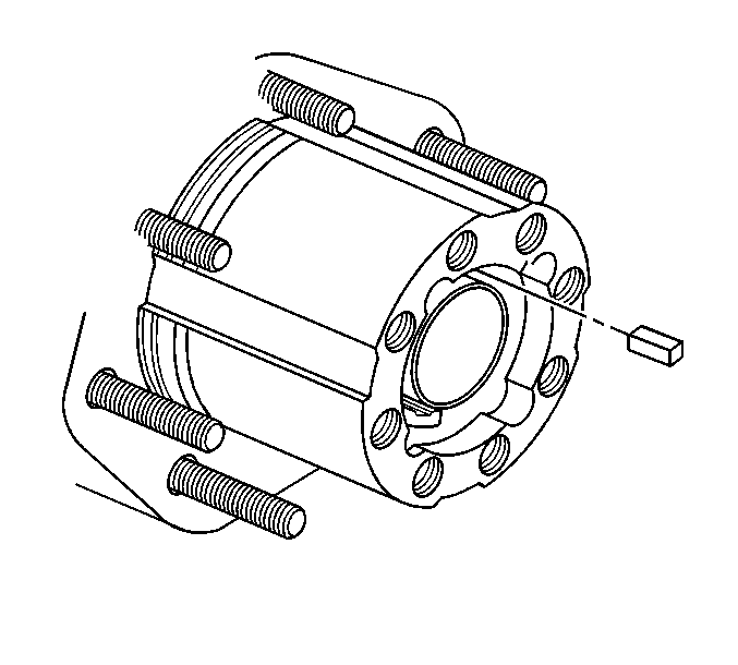
- Remove the adjuster nut lock key.
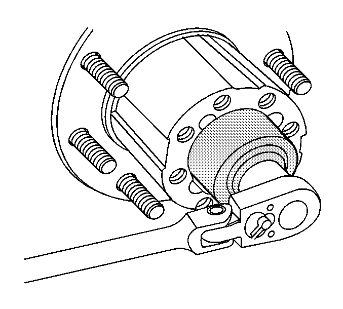
- Tighten the wheel bearing adjusting nut using the J 2222-C.
- Turn the adjusting nut counterclockwise until the nut is loose using the J 2222-C.
- Turn the adjusting nut clockwise until the nut contacts the bearing cone. Torque on the nut must be zero to finger tight.
- Insert the adjusting nut lock key into the keyway using one of the following procedures:
- Install the retaining ring.
- Install the axle shaft. Refer to Rear Axle Shaft and/or Gasket Replacement.
- Inspect the lubricant level and add, if necessary. Refer to Lubricant Level Check.
- Lower the vehicle.


Notice: Refer to Fastener Notice in Cautions and Notices.
Rotate the hub in the opposite direction to the way the adjuster nut is turning.
Ensure the inner bearing and the seal seats against the spindle shoulder.
Tighten
Tighten the adjusting nut to 70 N·m (52 lb ft).

| • | If the adjusting nut slot is in alignment with the keyway in the axle spindle, insert the adjusting nut lock key into the keyway in the axle spindle. |
| Important: Do not turn the adjusting nut more than one slot counterclockwise in order to align the adjusting nut slot with the keyway in the axle spindle. |
| • | If the adjusting nut slot is not aligned with the keyway in the axle spindle, turn the adjusting nut counterclockwise until the adjusting nut slot is in alignment with the keyway in the axle spindle and insert the adjusting nut lock key. |

