For 1990-2009 cars only
Removal Procedure
- Remove the left sound insulator. Refer to Instrument Panel Insulator Panel Replacement - Left Side in Instrument Panel, Gages, and Console.
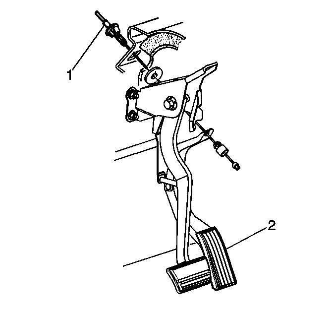
- Depress the accelerator control cable tangs (1) from the pedal lever assembly.
- Remove the accelerator control cable from the pedal lever assembly.
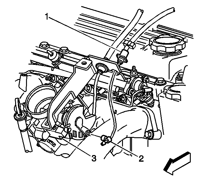
- Remove the cruise control cable (1), if applicable.
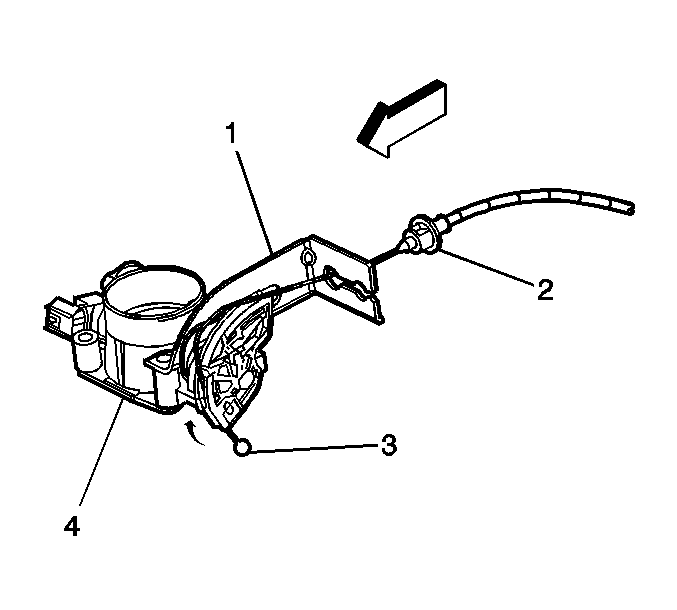
- Release the accelerator control cable lug (3) from the throttle body assembly (4).
- Depress the tangs on the accelerator control cable (2) while pulling the accelerator control cable through the accelerator control cable bracket (1).
- Remove the accelerator control cable from the bracket.
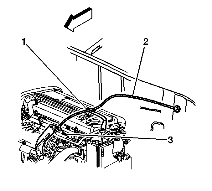
- Disconnect the accelerator control cable (2) from the support clip (1).
- Remove the cable from the vehicle.


Installation Procedure
- Route the accelerator control cable (2) through the accelerator control cable bracket (1).
- Press the accelerator control cable tabs (2) into the accelerator control bracket (1).
- Install the control cable lug (3) to the throttle body cam.
- Connect the accelerator control cable (2) to the support clip (1).
- Install the cruise control cable (2), if applicable.
- Install the cable (1) to the pedal lever assembly. Ensure the tangs are fully expanded and seated.
- Slip the accelerator cable through the slot in the rod of the accelerator pedal and install the retainer in the rod. Ensure the retainer is seated.
- Ensure the cable is completely seated in the throttle cam past the retaining clips.
- Inspect for the correct opening and closing positions by operating the accelerator pedal. Make sure that the throttle valve reaches wide open throttle (WOT) position. If not, inspect for damaged or a bent bracket or lever
- Install the left sound insulator. Refer to Instrument Panel Insulator Panel Replacement - Left Side in Instrument Panel, Gages, and Console.

Ensure the tangs expand and properly seat.


Important: Flexible components, hoses, wires, conduits, must not be routed within 50 mm (2.0 in) of the moving parts of the accelerator linkage outboard support unless the routing is positively controlled.
